EP0554542B1 - Elément pour impression en offset - Google Patents
Elément pour impression en offset Download PDFInfo
- Publication number
- EP0554542B1 EP0554542B1 EP92120894A EP92120894A EP0554542B1 EP 0554542 B1 EP0554542 B1 EP 0554542B1 EP 92120894 A EP92120894 A EP 92120894A EP 92120894 A EP92120894 A EP 92120894A EP 0554542 B1 EP0554542 B1 EP 0554542B1
- Authority
- EP
- European Patent Office
- Prior art keywords
- forme
- printing forme
- register
- offset printing
- cylinder
- Prior art date
- Legal status (The legal status is an assumption and is not a legal conclusion. Google has not performed a legal analysis and makes no representation as to the accuracy of the status listed.)
- Expired - Lifetime
Links
- 238000007645 offset printing Methods 0.000 title claims description 27
- 238000007639 printing Methods 0.000 claims description 53
- 238000000034 method Methods 0.000 claims description 12
- 238000003466 welding Methods 0.000 claims description 9
- 239000007769 metal material Substances 0.000 claims description 8
- 238000004519 manufacturing process Methods 0.000 claims description 7
- 229910052751 metal Inorganic materials 0.000 claims description 7
- 239000002184 metal Substances 0.000 claims description 7
- 229910052782 aluminium Inorganic materials 0.000 claims description 4
- XAGFODPZIPBFFR-UHFFFAOYSA-N aluminium Chemical compound [Al] XAGFODPZIPBFFR-UHFFFAOYSA-N 0.000 claims description 4
- 239000000463 material Substances 0.000 claims description 3
- 239000000853 adhesive Substances 0.000 claims description 2
- 230000001070 adhesive effect Effects 0.000 claims description 2
- 239000004411 aluminium Substances 0.000 claims 1
- 239000011248 coating agent Substances 0.000 description 2
- 238000000576 coating method Methods 0.000 description 2
- 230000001427 coherent effect Effects 0.000 description 2
- 229910000831 Steel Inorganic materials 0.000 description 1
- 238000002048 anodisation reaction Methods 0.000 description 1
- 238000007646 gravure printing Methods 0.000 description 1
- 150000002739 metals Chemical class 0.000 description 1
- 239000010959 steel Substances 0.000 description 1
Images

Classifications
-
- B—PERFORMING OPERATIONS; TRANSPORTING
- B41—PRINTING; LINING MACHINES; TYPEWRITERS; STAMPS
- B41N—PRINTING PLATES OR FOILS; MATERIALS FOR SURFACES USED IN PRINTING MACHINES FOR PRINTING, INKING, DAMPING, OR THE LIKE; PREPARING SUCH SURFACES FOR USE AND CONSERVING THEM
- B41N1/00—Printing plates or foils; Materials therefor
- B41N1/16—Curved printing plates, especially cylinders
- B41N1/20—Curved printing plates, especially cylinders made of metal or similar inorganic compounds, e.g. plasma coated ceramics, carbides
-
- B—PERFORMING OPERATIONS; TRANSPORTING
- B41—PRINTING; LINING MACHINES; TYPEWRITERS; STAMPS
- B41F—PRINTING MACHINES OR PRESSES
- B41F27/00—Devices for attaching printing elements or formes to supports
- B41F27/005—Attaching and registering printing formes to supports
-
- B—PERFORMING OPERATIONS; TRANSPORTING
- B41—PRINTING; LINING MACHINES; TYPEWRITERS; STAMPS
- B41F—PRINTING MACHINES OR PRESSES
- B41F27/00—Devices for attaching printing elements or formes to supports
- B41F27/12—Devices for attaching printing elements or formes to supports for attaching flexible printing formes
-
- B—PERFORMING OPERATIONS; TRANSPORTING
- B41—PRINTING; LINING MACHINES; TYPEWRITERS; STAMPS
- B41F—PRINTING MACHINES OR PRESSES
- B41F27/00—Devices for attaching printing elements or formes to supports
- B41F27/12—Devices for attaching printing elements or formes to supports for attaching flexible printing formes
- B41F27/1212—Devices for attaching printing elements or formes to supports for attaching flexible printing formes using pneumatic force
-
- Y—GENERAL TAGGING OF NEW TECHNOLOGICAL DEVELOPMENTS; GENERAL TAGGING OF CROSS-SECTIONAL TECHNOLOGIES SPANNING OVER SEVERAL SECTIONS OF THE IPC; TECHNICAL SUBJECTS COVERED BY FORMER USPC CROSS-REFERENCE ART COLLECTIONS [XRACs] AND DIGESTS
- Y10—TECHNICAL SUBJECTS COVERED BY FORMER USPC
- Y10S—TECHNICAL SUBJECTS COVERED BY FORMER USPC CROSS-REFERENCE ART COLLECTIONS [XRACs] AND DIGESTS
- Y10S101/00—Printing
- Y10S101/36—Means for registering or alignment of print plates on print press structure
-
- Y—GENERAL TAGGING OF NEW TECHNOLOGICAL DEVELOPMENTS; GENERAL TAGGING OF CROSS-SECTIONAL TECHNOLOGIES SPANNING OVER SEVERAL SECTIONS OF THE IPC; TECHNICAL SUBJECTS COVERED BY FORMER USPC CROSS-REFERENCE ART COLLECTIONS [XRACs] AND DIGESTS
- Y10—TECHNICAL SUBJECTS COVERED BY FORMER USPC
- Y10T—TECHNICAL SUBJECTS COVERED BY FORMER US CLASSIFICATION
- Y10T29/00—Metal working
- Y10T29/49—Method of mechanical manufacture
- Y10T29/49544—Roller making
- Y10T29/49547—Assembling preformed components
- Y10T29/49558—Includes securing removable cover on roller
Definitions
- the invention relates to an offset printing form made of a metallic material for a forme cylinder of a printing press and a method for producing such an offset printing form.
- the most common forms of printing in offset printing are the pre-coated aluminum plates, the great advantage of which is the simplicity and speed of manufacture, or the multi-metal plates, which mostly consist of three metals (trimetal), aluminum or steel sheet being generally used as the carrier metal. These types are particularly suitable for larger print runs and high loads. In addition, their good surface properties can be significantly improved by additional anodization.
- this printing form has fitting holes for the dowel pins of a clamping device of the printing form cylinder on two opposite edges.
- the printing form is centered on the dowel pins and hooked into a cylinder channel with the leading edge, which was previously bent over.
- the end of the printing form is also inserted into the cylinder channel so that the printing form can be clamped.
- This requires a channel across the cylinder width and clamping segments that extend through the cylinder in the channel.
- the printing forms begin and end in this area. This interruption of the printing form means that endless images cannot be produced.
- the printing speed is limited due to vibration loads of the cylinder through the channel and the clamping device. This vibration exposure also affects print quality.
- GB-A-578 777 discloses a printing form in which the mutually facing, folded plate edges are welded to one another on the cylinder, but are otherwise designed for gravure printing.
- the object of the present invention is to improve the print quality achieved by a generic printing form by eliminating the above-mentioned vibration load and at the same time allowing a higher rotational speed of the printing form cylinder.
- This offset printing form produced by the method according to the invention can be used in conjunction with a forme cylinder without a channel and clamping segment, which is known, for example, from German patent step DE-PS 27 00 118.
- the offset printing form can be pushed onto the form cylinder using compressed air. In the working position, it is displaceable on the forme cylinder, yet it can be easily removed from it without destroying it and can therefore be reused.
- the use of conventional printing form clamping devices, the channel and clamping segments are no longer necessary and can thus be saved. Only register devices are required to apply the printing form in accordance with the register.
- Known devices such as markings on the surface of the forme cylinder, which are brought into line with markings on the thin offset printing form, or register pins of the form cylinder, into which the printing form can be hung in register, can also be used here.
- commercially available offset printing plates can be used and previous plate copies can be used unchanged. The channelless printing enables cost-effective cylinder production, an improvement in print quality and higher printing speeds.
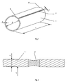
- a thin offset printing form 1 with a thickness s of approximately 0.3 mm is formed from a metallic material to form a sleeve with a diameter d of approximately 300 mm and a width l of approximately 1,600 mm.
- the material can be aluminum or a multi-metal or tri-metal.
- the beginning and end of offset printing form 1 are longitudinally welded together.
- the weld seam 2 preferably has a width b of approximately 0.7 mm.
- the weld seam 2 has a concave shape on its top and bottom, so that it is not noticeable on the print.
- Printing form 1 thus has a coherent, channel-free outer surface.
- the printing form 1 On one end face 3 (FIG. 3), the printing form 1 is provided with register devices in the form of fitting bores 4, which cooperate with register pins on the surface of the forme cylinder.
- register devices On one end face 3 (FIG. 3), the printing form 1 is provided with register devices in the form of fitting bores 4, which cooperate with register pins on the surface of the forme cylinder.
- the production process for printing form 1 comprises the following steps.
- a plate is cut to the size corresponding to the circumference and the width of the forme cylinder.
- At least one end face 3 or 5 is provided with register devices 4, 6 by means of a plate punch.
- the plate-shaped blank is clamped in register in the form of a sleeve in a welding device and the beginning and end of the printing form 1 are welded lengthwise. This is preferably done using a neodymium-YAG laser.
- the regulation of the laser power and the possibility of a continuous and pulsed operating mode allow a controlled and exactly reproducible energy influence on the printing form 1. Heat load and warpage of the weld metal are extremely low in comparison with other thermal processes.
- the welding process is carried out in such a way that a weld seam 2 is formed which has a concave shape on the top and bottom.
- the sleeve-shaped printing forme 1 is then pushed onto the forme cylinder while expanding by means of compressed air.
- the removal of the compressed air causes the printing form to adhere positively to the forme cylinder.
- the coating and exposure of the printing form 1 can be carried out on the one hand before the beginning and end of the printing form 1 outside the printing press by photochemical means, and on the other hand after the sleeve-shaped printing form 1 has been pushed on by coating and exposing the printing form on the form cylinder all around.
- the principle of the invention is therefore to form a commercially available pressure plate made of a metallic material for the purpose of channelless printing into a sleeve, which frictionally and register-wise in the working position, but releasably and reusably encased the forme cylinder and thus has a coherent channel-free outer surface.
- the invention is not limited to a printing form which is formed into a sleeve by means of a weld seam. It is also conceivable to establish the connection between the beginning and end of the printing form by means of an adhesive bond, for example the beginning of the printing form being glued to half of a longitudinal saddle, the end of the printing form glued to the other half of the longitudinal saddle and the joints from the beginning and end are additionally glued. Then the sleeve-shaped printing form together with the saddle is pushed onto the forme cylinder.
Landscapes
- Chemical & Material Sciences (AREA)
- Engineering & Computer Science (AREA)
- Ceramic Engineering (AREA)
- Inorganic Chemistry (AREA)
- Printing Plates And Materials Therefor (AREA)
- Supply, Installation And Extraction Of Printed Sheets Or Plates (AREA)
- Manufacture Or Reproduction Of Printing Formes (AREA)
Claims (12)
- Plaque d'impression offset en matériau métallique destinée à un cylindre porte-plaque d'une presse d'imprimerie, la plaque d'impression étant amenée par cintrage d'une plaque rectangulaire (1) en une forme de cylindre creux, les bords de la plaque (1) se mettant l'un contre l'autre étant reliés l'un à l'autre d'une manière fixe, de sorte que la plaque d'impression offset dispose d'une surface externe sans canal continue et puisse être transférée sur le cylindre porte-plaque par entraînement par friction, de manière toutefois amovible et des dispositifs de repérage (4, 6) étant prévus sur au moins une face (3, 5) pour assurer le repérage selon la périphérie et latéralement.
- Plaque d'impression offset selon la revendication 1, caractérisée en ce que le début et la fin de la plaque d'impression offset (1) sont reliés au moyen d'une soudure (2).
- Plaque d'impression offset selon la revendication 1, caractérisée en ce que le début et la fin de la plaque d'impression offset (1) sont reliés au moyen d'un collage, le début de la plaque d'impression (1) étant collé sur une moitié d'une assise se développant longitudinalement et la fin de la plaque d'impression (1) étant collée sur l'autre moitié de l'assise.
- Plaque d'impression offset selon la revendication 1, caractérisée en ce que le matériau est de l'aluminium.
- Plaque d'impression offset selon la revendication 1, caractérisée en ce que le matériau est un matériau polymétallique.
- Plaque d'impression offset selon la revendication 1, caractérisée en ce que les dispositifs de repérage sont développés en forme de trous d'ajustage (4), qui coopèrent avec des goujons de repérage sur la surface du cylindre porte-plaque.
- Plaque d'impression offset selon la revendication 1, caractérisée en ce que les dispositifs de repérage sont développés en forme de creux (6) sur les deux faces (3, 5) de la plaque d'impression (1), qui coopèrent avec des goujons de repérage sur la surface du cylindre porte-plaque.
- Procédé pour la fabrication d'une plaque d'impression offset en matériau métallique destinée à un cylindre porte-plaque d'une presse d'imprimerie, caractérisé en ce qu'une plaque est découpée à la mesure correspondant au périmètre et à la largeur du cylindre porte-plaque et est pourvue sur au moins une face (3, 5) de dispositifs de repérage (4, 6), en ce que la découpe en forme de plaque est sensibilisée et insolée par une technique traditionnelle, est mise en forme de manchon en fonction du repérage dans un dispositif de soudage, en ce que le début et la fin de la plaque d'impression (1) sont soudés par soudure longitudinale, le procédé de soudage étant établi de sorte qu'une soudure (2), qui présente une forme concave au niveau des surfaces inférieure et supérieure, se produise et en ce que la plaque d'impression (1) en forme de manchon est enfilée sur le cylindre porte-plaque par élargissement au moyen d'air comprimé.
- Procédé pour la fabrication d'une plaque d'impression offset en matériau métallique destinée à un cylindre porte-plaque d'une presse d'imprimerie, caractérisé en ce qu'une plaque est découpée à la mesure correspondant au périmètre et à la largeur du cylindre porte-plaque et est pourvue sur au moins une face (3, 5) de dispositifs de repérage (4, 6), en ce que la découpe en forme de plaque est mise en forme de manchon dans un dispositif de soudage, en ce que le début et la fin de la plaque sont soudés par soudure longitudinale, le procédé de soudage étant établi de sorte qu'une soudure (2), qui présente une forme concave au niveau des surfaces inférieure et supérieure, se présente et en ce que la plaque (1) en forme de manchon est enfilée sur le cylindre porte-plaque par élargissement au moyen d'air comprimé et en ce que la plaque (1) est sensibilisée et insolée circulairement sur le cylindre porte-plaque selon un ajustement serré.
- Procédé selon la revendication 8 ou 9, caractérisé en ce que la découpe en forme de plaque au moyen d'une matrice de plaques est pourvue de trous d'ajustage (4) en tant que dispositifs de repérage.
- Procédé selon la revendication 8 ou 9, caractérisé en ce que pour le procédé de soudage est utilisé un laser YAG au néodyme.
- Procédé pour la fabrication d'une plaque d'impression offset en matériau métallique destinée à un cylindre porte-plaque d'une presse d'imprimerie, caractérisé en ce qu'une plaque est découpée à la mesure correspondant au périmètre et à la largeur du cylindre porte-plaque, des marquages sont mis en place au début et à la fin de la plaque au moins au niveau d'une face, le début de la plaque d'impression est collé sur une moitié d'une assise se développant longitudinalement, la fin de la plaque d'impression (1) est collée conformément au repérage sur l'autre moitié de l'assise et la plaque d'impression est glissée avec l'assise sur le cylindre.
Applications Claiming Priority (2)
| Application Number | Priority Date | Filing Date | Title |
|---|---|---|---|
| DE4140768 | 1991-12-11 | ||
| DE4140768A DE4140768C2 (de) | 1991-12-11 | 1991-12-11 | Offset-Druckform |
Publications (2)
| Publication Number | Publication Date |
|---|---|
| EP0554542A1 EP0554542A1 (fr) | 1993-08-11 |
| EP0554542B1 true EP0554542B1 (fr) | 1996-04-10 |
Family
ID=6446760
Family Applications (1)
| Application Number | Title | Priority Date | Filing Date |
|---|---|---|---|
| EP92120894A Expired - Lifetime EP0554542B1 (fr) | 1991-12-11 | 1992-12-08 | Elément pour impression en offset |
Country Status (5)
| Country | Link |
|---|---|
| US (1) | US5379693A (fr) |
| EP (1) | EP0554542B1 (fr) |
| JP (1) | JP3272427B2 (fr) |
| CA (1) | CA2083682C (fr) |
| DE (2) | DE4140768C2 (fr) |
Cited By (2)
| Publication number | Priority date | Publication date | Assignee | Title |
|---|---|---|---|---|
| DE102005035858B3 (de) * | 2005-07-30 | 2006-07-13 | Koenig & Bauer Ag | Vorrichtung zum Aufziehen eines Sleeves auf einen Druckzylinder |
| DE102005035857A1 (de) * | 2005-07-30 | 2007-02-01 | Koenig & Bauer Ag | Druckzylinder |
Families Citing this family (53)
| Publication number | Priority date | Publication date | Assignee | Title |
|---|---|---|---|---|
| DE4311078C1 (de) * | 1993-04-03 | 1994-05-26 | Roland Man Druckmasch | Vorrichtung zur Erzeugung einer Hülse, insbesondere einer hülsenförmigen Druckform, mit zusammenhängender Umfangsfläche |
| DE4412873C2 (de) * | 1993-05-13 | 1995-06-22 | Roland Man Druckmasch | Registereinrichtung für eine hülsenförmige Offset-Druckform |
| DE4315996C1 (de) * | 1993-05-13 | 1994-08-04 | Roland Man Druckmasch | Registereinrichtung für eine hülsenförmige Offset-Druckform |
| DE4323750C2 (de) * | 1993-07-15 | 1997-03-27 | Roland Man Druckmasch | Offset-Druckform und Verfahren zur Herstellung einer solchen Offset-Druckform |
| DE4338467C1 (de) * | 1993-11-11 | 1995-02-23 | Roland Man Druckmasch | Verfahren zur Herstellung einer hülsenförmigen Druckform |
| DE4342159C2 (de) * | 1993-12-10 | 1997-04-10 | Roland Man Druckmasch | Formzylinder für eine hülsenförmige Druckform |
| DE4401269A1 (de) * | 1994-01-18 | 1995-07-20 | Roland Man Druckmasch | Verfahren und Vorrichtung zum registergerechten Positionieren von Druckformhülsen |
| DE4432814A1 (de) | 1994-09-15 | 1996-03-28 | Roland Man Druckmasch | Trägerhülse für Druck- und Übertragungsformen |
| DE4432853C2 (de) * | 1994-09-15 | 1999-09-02 | Roland Man Druckmasch | Trägerhülse für Druck- und Übertragungsformen |
| US6779449B1 (en) | 1994-09-15 | 2004-08-24 | Man Roland Druckmaschinen Ag | Carrying sleeve for printing and transfer forms and a process for production of such a carrying sleeve |
| US5507228A (en) * | 1994-10-03 | 1996-04-16 | Schulz; Werner | Printing cylinder |
| US5481975A (en) * | 1994-10-03 | 1996-01-09 | Schulz; Werner | Printing cylinder mandrel and image carrier sleeve |
| JPH08300172A (ja) * | 1995-04-28 | 1996-11-19 | Nkk Corp | 溶接鋼管の製造方法 |
| DE19525585C2 (de) * | 1995-07-13 | 2003-03-27 | Roland Man Druckmasch | Rotationsdruckmaschine, insbesondere Offsetdruckmaschine |
| US5778779A (en) * | 1996-01-04 | 1998-07-14 | Heidelberger Druckmaschinen Ag | Printing unit and register mechanism for mounting a printing sleeve |
| FR2746539B1 (fr) * | 1996-03-21 | 1998-05-22 | Kertscher Sa E | Procede de fabrication de cables coaxiaux |
| US5687647A (en) * | 1996-04-26 | 1997-11-18 | Heidelberger Druckmaschinen Ag | Plate cylinder with fixed tensioning plate mounting device |
| DE19720551A1 (de) * | 1997-05-16 | 1998-11-19 | Heidelberger Druckmasch Ag | Basisträgerhülse für Rotationsdruckmaschinen |
| DE19720549A1 (de) * | 1997-05-16 | 1998-11-19 | Heidelberger Druckmasch Ag | Verfahren zur Herstellung von zylindrischen Beschichtungsträgern |
| FR2764842B1 (fr) * | 1997-06-24 | 1999-09-24 | Jean Francille | Dispositif de guidage integre pour manchon ou cylindre d'impression et manchon ou cylindre equipe de ce dispositif |
| US6075955A (en) * | 1998-01-23 | 2000-06-13 | Mitsubishi Chemical America, Inc. | Noise reducing device for photosensitive drum of an image forming apparatus |
| DE19804269A1 (de) * | 1998-02-04 | 1999-08-05 | Heidelberger Druckmasch Ag | Vorrichtung zum Auftragen einer Flüssigkeit auf einen Bedruckstoffbogen, insbesondere Druck, oder Lackierwerk, in einer Bogenrotationsdruckmaschine |
| US5974972A (en) * | 1998-04-06 | 1999-11-02 | Van Denend; Mark E. | Printing carrier sleeves and method for manufacturing the same |
| DE19820357C1 (de) | 1998-05-07 | 1999-10-07 | Roland Man Druckmasch | Verfahren und Vorrichtung zum Bearbeiten einer Schweißnaht an eine Trägerhülse |
| US6283026B1 (en) * | 1998-11-02 | 2001-09-04 | Polybribron Technologies S.A. | Device for automatically blocking air passages in cylinder, specifically for support cylinders and compensation mantles |
| US6161479A (en) * | 1998-12-23 | 2000-12-19 | Heidelberger Druckmaschinen Ag | Printing plate for a lithographic rotary printing press |
| GB9918881D0 (en) * | 1999-08-10 | 1999-10-13 | Neopost Ltd | Ink dispenser |
| DE19938846B4 (de) * | 1999-08-17 | 2004-08-26 | Alcan Deutschland Gmbh | Verfahren zur Herstellung eines Hohlkörpers aus Aluminium oder einer Aluminiumlegierung |
| JP2001150145A (ja) * | 1999-12-01 | 2001-06-05 | Mitsubishi Electric Corp | ストリップ接続装置及び方法 |
| DE10049283A1 (de) * | 2000-10-05 | 2002-04-11 | Hueck Folien Gmbh & Co Kg | Verfahren und Vorrichtung zur Herstellung einer zylindrischen Prägeform |
| US6539629B2 (en) * | 2001-01-26 | 2003-04-01 | Great Computer Corp. | Roller shaft on computer character-cutting device and method to manufacture the same |
| DE10133726B4 (de) * | 2001-07-11 | 2006-10-05 | Eastman Kodak Co. | Verfahren zum Herstellen einer Manschette |
| DE10151816B4 (de) * | 2001-10-20 | 2011-04-28 | Manroland Ag | Hülsenförmige Druck- oder Übertragungsform und Gerät zum Anfasen der Längenenden einer hülsenförmigen Druck- oder Übertragungsform |
| AU2002225331A1 (en) * | 2001-12-20 | 2003-07-09 | Rotoincisa S.R.L. | Process for preparing removable metal sleeves for printing machines |
| US6894713B2 (en) | 2002-02-08 | 2005-05-17 | Kodak Polychrome Graphics Llc | Method and apparatus for laser-induced thermal transfer printing |
| US7439995B2 (en) * | 2002-02-08 | 2008-10-21 | Kodak Polychrome Graphics, Gmbh | Method and apparatus for laser induced thermal transfer printing |
| DE10250683B3 (de) * | 2002-10-31 | 2004-03-18 | Koenig & Bauer Ag | Verfahren zur Herstellung eines Rotationskörpers einer Druckmaschine und einen danach hergestellten Rotationskörper |
| DE10260445A1 (de) * | 2002-12-21 | 2004-07-08 | Man Roland Druckmaschinen Ag | Vorrichtung zur Erzeugung einer hülsenförmigen Druckform |
| US6779450B1 (en) | 2003-04-21 | 2004-08-24 | Agfa Corporation | Thin-wall drum for external drum imaging system |
| DE10342353A1 (de) * | 2003-09-12 | 2005-04-21 | Iwka Balg Und Kompensatoren Te | Verfahren zur Herstellung von Anschlussenden an Metallschläuchen und Schlauchstück mit solchen Anschlussenden |
| DE102004051041B3 (de) * | 2004-10-20 | 2006-03-02 | Windmöller & Hölscher Kg | Druckplattenzylinder |
| DE102007047172A1 (de) * | 2007-10-02 | 2009-04-09 | Manroland Ag | Gummisleeve |
| US20090211475A1 (en) | 2008-02-21 | 2009-08-27 | Taylor Bradley K | Extended print sleeve and method for preparing a printing form from the sleeve |
| JP2010184806A (ja) * | 2009-02-13 | 2010-08-26 | Seiko Epson Corp | 搬送ローラー、搬送ユニット、及び印刷装置 |
| JP5402054B2 (ja) * | 2009-02-13 | 2014-01-29 | セイコーエプソン株式会社 | 搬送ローラー、搬送ユニット、及び印刷装置 |
| WO2011077944A1 (fr) * | 2009-12-24 | 2011-06-30 | ユニバーサル製缶株式会社 | Cylindre porte-plaque pour plaque d'impression à manchon, procédé d'utilisation de cylindre porte-plaque pour plaque d'impression à manchon, et appareil d'impression de boîte |
| US20130139714A1 (en) * | 2011-12-02 | 2013-06-06 | E.I. Du Pont De Nemours And Company | Method for making flexographic printing forms by welding edges of photosensitive elements with microwave energy |
| US9878531B2 (en) | 2013-12-19 | 2018-01-30 | Goss International Americas, Inc. | Reimageable and reusable printing sleeve for a variable cutoff printing press |
| JP6316121B2 (ja) * | 2014-06-30 | 2018-04-25 | 昭和アルミニウム缶株式会社 | 版胴、版装着装置 |
| JP6559411B2 (ja) * | 2014-11-04 | 2019-08-14 | 昭和アルミニウム缶株式会社 | 印刷用版の成形方法及び印刷用版の円筒状成形装置 |
| JP2016104532A (ja) * | 2014-12-01 | 2016-06-09 | 昭和アルミニウム缶株式会社 | 印刷用版 |
| DE102018000696A1 (de) * | 2018-01-29 | 2019-08-01 | Giesecke+Devrient Currency Technology Gmbh | Verfahren zum Befestigen eines Prägewerkzeugs auf einer Prägewalze |
| CN115230294A (zh) * | 2021-04-23 | 2022-10-25 | 山东新巨丰泰东包装有限公司 | 印版 |
Family Cites Families (17)
| Publication number | Priority date | Publication date | Assignee | Title |
|---|---|---|---|---|
| US758486A (en) * | 1903-06-06 | 1904-04-26 | Benjamin J Such | Printing-roller. |
| US1963745A (en) * | 1932-07-05 | 1934-06-19 | Ingersoll Steel And Disc Co | Process of making composite metal articles |
| GB578777A (en) * | 1942-05-11 | 1946-07-11 | Interchem Corp | Improvements in or relating to rotogravure printing members and method of making the same |
| DE2045953C3 (de) * | 1970-09-17 | 1981-10-22 | Heinz 5653 Leichlingen Metje | Paßsystem zum Einpassen von Druckplatten in Offset-Rollen-Rotationsmachinen |
| IN146438B (fr) * | 1976-01-08 | 1979-06-02 | Strachan & Henshaw Ltd | |
| JPS5432154A (en) * | 1977-08-16 | 1979-03-09 | Kawasaki Steel Co | Weld bonding of belt steel coil by belt steels mutual bonding |
| US4286031A (en) * | 1978-06-22 | 1981-08-25 | Coulter Stork U.S.A., Inc. | Electrostatic multicolor composite printing method and apparatus |
| EP0009360B2 (fr) * | 1978-09-13 | 1991-03-20 | Drg (Uk) Limited | Fabrication de douilles pour l'impression |
| DE3663480D1 (en) * | 1985-07-26 | 1989-06-29 | De La Rue Giori Sa | Method and installation for fixing a printing plate on a printing cylinder |
| US4727806A (en) * | 1985-08-26 | 1988-03-01 | Wilson Engraving Company, Inc. | Pin register system for flexographic printing plates |
| GB2179890A (en) * | 1985-08-29 | 1987-03-18 | Wilson Engraving Inc | Pin register system in production of printing plates |
| DE3543704A1 (de) * | 1985-12-11 | 1987-06-19 | Md Papierfabrik Pasing Nicolau | Vorrichtung und verfahren zum bedrucken einer bahn |
| DE3633155A1 (de) * | 1986-09-30 | 1988-04-07 | Saueressig & Co | Druckzylinder, insbesondere fuer das flexodruckverfahren |
| IT1231223B (it) * | 1987-09-11 | 1991-11-26 | Cerutti Spa Off Mec | Metodo per giuntare le estremita' di una lastra per la stampa rotativa e giunzione cosi' ottenuta |
| US5138923A (en) * | 1988-11-18 | 1992-08-18 | Atlas Die, Inc. | Rotary die cutter |
| US5052120A (en) * | 1990-04-16 | 1991-10-01 | Eastman Kodak Company | Sheet positioning, clamping, and tensioning means |
| DE4125931A1 (de) * | 1991-08-05 | 1993-02-11 | Gerhardt Int As | Verfahren zur herstellung eines walzenfoermigen praegewerkzeugs |
-
1991
- 1991-12-11 DE DE4140768A patent/DE4140768C2/de not_active Expired - Fee Related
-
1992
- 1992-11-24 CA CA002083682A patent/CA2083682C/fr not_active Expired - Fee Related
- 1992-12-04 US US07/986,425 patent/US5379693A/en not_active Expired - Lifetime
- 1992-12-08 DE DE59205967T patent/DE59205967D1/de not_active Expired - Lifetime
- 1992-12-08 EP EP92120894A patent/EP0554542B1/fr not_active Expired - Lifetime
- 1992-12-09 JP JP32930392A patent/JP3272427B2/ja not_active Expired - Fee Related
Cited By (3)
| Publication number | Priority date | Publication date | Assignee | Title |
|---|---|---|---|---|
| DE102005035858B3 (de) * | 2005-07-30 | 2006-07-13 | Koenig & Bauer Ag | Vorrichtung zum Aufziehen eines Sleeves auf einen Druckzylinder |
| DE102005035857A1 (de) * | 2005-07-30 | 2007-02-01 | Koenig & Bauer Ag | Druckzylinder |
| DE102005035857B4 (de) * | 2005-07-30 | 2011-10-13 | Koenig & Bauer Aktiengesellschaft | Druckzylinder |
Also Published As
| Publication number | Publication date |
|---|---|
| DE4140768C2 (de) | 1994-08-18 |
| CA2083682A1 (fr) | 1993-06-12 |
| DE4140768A1 (de) | 1993-06-17 |
| JP3272427B2 (ja) | 2002-04-08 |
| US5379693A (en) | 1995-01-10 |
| JPH05254096A (ja) | 1993-10-05 |
| DE59205967D1 (de) | 1996-05-15 |
| EP0554542A1 (fr) | 1993-08-11 |
| CA2083682C (fr) | 1996-10-29 |
Similar Documents
| Publication | Publication Date | Title |
|---|---|---|
| DE4140768C2 (de) | Offset-Druckform | |
| DE4217793C1 (de) | Offset-Gummituch und Verfahren zu dessen Herstellung | |
| DD250900A5 (de) | Verfahren und vorrichtung zum bedrucken einer bahn | |
| DE4323750C2 (de) | Offset-Druckform und Verfahren zur Herstellung einer solchen Offset-Druckform | |
| DE4315996C1 (de) | Registereinrichtung für eine hülsenförmige Offset-Druckform | |
| EP1068077B1 (fr) | Dispositif de perforage, rainage ou decoupage destine a des rotatives a feuilles pour impression en polychromie | |
| CH693589A5 (de) | Verfahren und Vorrichtung zum Aufbringen einer Druckform auf einen Formzylinder. | |
| EP0653313B1 (fr) | Procédé de fabrication d'une forme d'impression en forme de manchon | |
| EP0221322A2 (fr) | Procédé d'application d'un revêtement de protection sur un cylindre d'impression et dispositif pour la mise en oeuvre du procédé | |
| DE19820357C1 (de) | Verfahren und Vorrichtung zum Bearbeiten einer Schweißnaht an eine Trägerhülse | |
| DE3006100C2 (de) | Offsetdruckmaschine | |
| EP1013467B1 (fr) | Plaque d'impression pour imprimante offset rotative | |
| DE3010642C2 (fr) | ||
| DE2604874C3 (de) | Einrichtung zum Einpassen von Druckplatten für Offset-Rollen-Rotationsdruckmaschinen | |
| EP0170956A2 (fr) | Procédé pour fixer des clichés flexibles sur le cylindre de forme d'une machine à imprimer | |
| DE2265153B2 (de) | Werkzeug für Stanzmaschinen | |
| DE68906168T2 (de) | Verfahren zum Befestigen und Positionieren von Offsetdruckplatten mit magnetischer Unterstützung und Druckplatte und Offsetdruckmaschine zur Durchführung des Verfahrens. | |
| DE19911821C2 (de) | Druckplatte und Verfahren zu ihrer Herstellung | |
| CH245086A (de) | Verfahren zum Einsetzen von Druckplatten in Tiefdruckzylinder. | |
| DE19954143C2 (de) | Druckplatte und Verfahren zu ihrer Herstellung | |
| EP0531741A1 (fr) | Dispositif pour fixer le bord avant d'un cliché dans une machine à imprimer | |
| EP0922545B1 (fr) | Dispositif pour poinçonner un matériau en forme de bande ou feuille et procédé de fabrication d'une plaque de support | |
| DE471023C (de) | Verfahren zur Herstellung von Rundgalvanos fuer Rotationsdruck | |
| DE29710871U1 (de) | Einrichtung zum Befestigen | |
| DE10203048A1 (de) | Verfahren und Vorrichtung zum Zuordnen von Registerungenauigkeiten bei Druckmaschinen |
Legal Events
| Date | Code | Title | Description |
|---|---|---|---|
| PUAI | Public reference made under article 153(3) epc to a published international application that has entered the european phase |
Free format text: ORIGINAL CODE: 0009012 |
|
| AK | Designated contracting states |
Kind code of ref document: A1 Designated state(s): CH DE FR GB IT LI NL SE |
|
| 17P | Request for examination filed |
Effective date: 19930901 |
|
| 17Q | First examination report despatched |
Effective date: 19940906 |
|
| ITF | It: translation for a ep patent filed | ||
| GRAH | Despatch of communication of intention to grant a patent |
Free format text: ORIGINAL CODE: EPIDOS IGRA |
|
| GRAA | (expected) grant |
Free format text: ORIGINAL CODE: 0009210 |
|
| AK | Designated contracting states |
Kind code of ref document: B1 Designated state(s): CH DE FR GB IT LI NL SE |
|
| REG | Reference to a national code |
Ref country code: CH Ref legal event code: NV Representative=s name: E. BLUM & CO. PATENTANWAELTE |
|
| REF | Corresponds to: |
Ref document number: 59205967 Country of ref document: DE Date of ref document: 19960515 |
|
| GBT | Gb: translation of ep patent filed (gb section 77(6)(a)/1977) |
Effective date: 19960704 |
|
| ET | Fr: translation filed | ||
| PLBI | Opposition filed |
Free format text: ORIGINAL CODE: 0009260 |
|
| PLBF | Reply of patent proprietor to notice(s) of opposition |
Free format text: ORIGINAL CODE: EPIDOS OBSO |
|
| 26 | Opposition filed |
Opponent name: KBA KOENIG & BAUER-ALBERT AG WERK WUERZBURG Effective date: 19961217 |
|
| NLR1 | Nl: opposition has been filed with the epo |
Opponent name: KBA KOENIG & BAUER-ALBERT AG WERK WUERZBURG |
|
| PLBF | Reply of patent proprietor to notice(s) of opposition |
Free format text: ORIGINAL CODE: EPIDOS OBSO |
|
| PLBO | Opposition rejected |
Free format text: ORIGINAL CODE: EPIDOS REJO |
|
| PLBN | Opposition rejected |
Free format text: ORIGINAL CODE: 0009273 |
|
| STAA | Information on the status of an ep patent application or granted ep patent |
Free format text: STATUS: OPPOSITION REJECTED |
|
| 27O | Opposition rejected |
Effective date: 19971217 |
|
| NLR2 | Nl: decision of opposition | ||
| PGFP | Annual fee paid to national office [announced via postgrant information from national office to epo] |
Ref country code: SE Payment date: 19981118 Year of fee payment: 7 |
|
| PG25 | Lapsed in a contracting state [announced via postgrant information from national office to epo] |
Ref country code: SE Free format text: LAPSE BECAUSE OF NON-PAYMENT OF DUE FEES Effective date: 19991209 |
|
| EUG | Se: european patent has lapsed |
Ref document number: 92120894.8 |
|
| REG | Reference to a national code |
Ref country code: GB Ref legal event code: IF02 |
|
| PGFP | Annual fee paid to national office [announced via postgrant information from national office to epo] |
Ref country code: CH Payment date: 20021119 Year of fee payment: 11 |
|
| PGFP | Annual fee paid to national office [announced via postgrant information from national office to epo] |
Ref country code: GB Payment date: 20021128 Year of fee payment: 11 |
|
| PGFP | Annual fee paid to national office [announced via postgrant information from national office to epo] |
Ref country code: NL Payment date: 20021130 Year of fee payment: 11 |
|
| PGFP | Annual fee paid to national office [announced via postgrant information from national office to epo] |
Ref country code: FR Payment date: 20021206 Year of fee payment: 11 |
|
| PG25 | Lapsed in a contracting state [announced via postgrant information from national office to epo] |
Ref country code: GB Free format text: LAPSE BECAUSE OF NON-PAYMENT OF DUE FEES Effective date: 20031208 |
|
| PG25 | Lapsed in a contracting state [announced via postgrant information from national office to epo] |
Ref country code: CH Free format text: LAPSE BECAUSE OF NON-PAYMENT OF DUE FEES Effective date: 20031231 Ref country code: LI Free format text: LAPSE BECAUSE OF NON-PAYMENT OF DUE FEES Effective date: 20031231 |
|
| PG25 | Lapsed in a contracting state [announced via postgrant information from national office to epo] |
Ref country code: NL Free format text: LAPSE BECAUSE OF NON-PAYMENT OF DUE FEES Effective date: 20040701 |
|
| GBPC | Gb: european patent ceased through non-payment of renewal fee |
Effective date: 20031208 |
|
| REG | Reference to a national code |
Ref country code: CH Ref legal event code: PL |
|
| PG25 | Lapsed in a contracting state [announced via postgrant information from national office to epo] |
Ref country code: FR Free format text: LAPSE BECAUSE OF NON-PAYMENT OF DUE FEES Effective date: 20040831 |
|
| NLV4 | Nl: lapsed or anulled due to non-payment of the annual fee |
Effective date: 20040701 |
|
| REG | Reference to a national code |
Ref country code: FR Ref legal event code: ST |
|
| PG25 | Lapsed in a contracting state [announced via postgrant information from national office to epo] |
Ref country code: IT Free format text: LAPSE BECAUSE OF NON-PAYMENT OF DUE FEES;WARNING: LAPSES OF ITALIAN PATENTS WITH EFFECTIVE DATE BEFORE 2007 MAY HAVE OCCURRED AT ANY TIME BEFORE 2007. THE CORRECT EFFECTIVE DATE MAY BE DIFFERENT FROM THE ONE RECORDED. Effective date: 20051208 |
|
| PGFP | Annual fee paid to national office [announced via postgrant information from national office to epo] |
Ref country code: DE Payment date: 20101222 Year of fee payment: 19 |
|
| REG | Reference to a national code |
Ref country code: DE Ref legal event code: R119 Ref document number: 59205967 Country of ref document: DE Effective date: 20120703 |
|
| PG25 | Lapsed in a contracting state [announced via postgrant information from national office to epo] |
Ref country code: DE Free format text: LAPSE BECAUSE OF NON-PAYMENT OF DUE FEES Effective date: 20120703 |