EP0554580A1 - Appareil pour la séparation de matières d'un liquide courant, méthode de fonctionnement et utilisation de cet appareil - Google Patents
Appareil pour la séparation de matières d'un liquide courant, méthode de fonctionnement et utilisation de cet appareil Download PDFInfo
- Publication number
- EP0554580A1 EP0554580A1 EP92200306A EP92200306A EP0554580A1 EP 0554580 A1 EP0554580 A1 EP 0554580A1 EP 92200306 A EP92200306 A EP 92200306A EP 92200306 A EP92200306 A EP 92200306A EP 0554580 A1 EP0554580 A1 EP 0554580A1
- Authority
- EP
- European Patent Office
- Prior art keywords
- screw conveyor
- tube
- bores
- pipe
- solids
- Prior art date
- Legal status (The legal status is an assumption and is not a legal conclusion. Google has not performed a legal analysis and makes no representation as to the accuracy of the status listed.)
- Granted
Links
Images

Classifications
-
- E—FIXED CONSTRUCTIONS
- E03—WATER SUPPLY; SEWERAGE
- E03F—SEWERS; CESSPOOLS
- E03F5/00—Sewerage structures
- E03F5/14—Devices for separating liquid or solid substances from sewage, e.g. sand or sludge traps, rakes or grates
-
- B—PERFORMING OPERATIONS; TRANSPORTING
- B01—PHYSICAL OR CHEMICAL PROCESSES OR APPARATUS IN GENERAL
- B01D—SEPARATION
- B01D29/00—Filters with filtering elements stationary during filtration, e.g. pressure or suction filters, not covered by groups B01D24/00 - B01D27/00; Filtering elements therefor
- B01D29/11—Filters with filtering elements stationary during filtration, e.g. pressure or suction filters, not covered by groups B01D24/00 - B01D27/00; Filtering elements therefor with bag, cage, hose, tube, sleeve or like filtering elements
- B01D29/31—Self-supporting filtering elements
- B01D29/35—Self-supporting filtering elements arranged for outward flow filtration
- B01D29/356—Self-supporting filtering elements arranged for outward flow filtration open-ended, the arrival of the mixture to be filtered and the discharge of the concentrated mixture are situated on both opposite sides of the filtering element
-
- B—PERFORMING OPERATIONS; TRANSPORTING
- B01—PHYSICAL OR CHEMICAL PROCESSES OR APPARATUS IN GENERAL
- B01D—SEPARATION
- B01D29/00—Filters with filtering elements stationary during filtration, e.g. pressure or suction filters, not covered by groups B01D24/00 - B01D27/00; Filtering elements therefor
- B01D29/60—Filters with filtering elements stationary during filtration, e.g. pressure or suction filters, not covered by groups B01D24/00 - B01D27/00; Filtering elements therefor integrally combined with devices for controlling the filtration
- B01D29/605—Filters with filtering elements stationary during filtration, e.g. pressure or suction filters, not covered by groups B01D24/00 - B01D27/00; Filtering elements therefor integrally combined with devices for controlling the filtration by level measuring
-
- B—PERFORMING OPERATIONS; TRANSPORTING
- B01—PHYSICAL OR CHEMICAL PROCESSES OR APPARATUS IN GENERAL
- B01D—SEPARATION
- B01D29/00—Filters with filtering elements stationary during filtration, e.g. pressure or suction filters, not covered by groups B01D24/00 - B01D27/00; Filtering elements therefor
- B01D29/62—Regenerating the filter material in the filter
- B01D29/64—Regenerating the filter material in the filter by scrapers, brushes, nozzles, or the like, acting on the cake side of the filtering element
- B01D29/6469—Regenerating the filter material in the filter by scrapers, brushes, nozzles, or the like, acting on the cake side of the filtering element scrapers
- B01D29/6476—Regenerating the filter material in the filter by scrapers, brushes, nozzles, or the like, acting on the cake side of the filtering element scrapers with a rotary movement with respect to the filtering element
-
- B—PERFORMING OPERATIONS; TRANSPORTING
- B01—PHYSICAL OR CHEMICAL PROCESSES OR APPARATUS IN GENERAL
- B01D—SEPARATION
- B01D29/00—Filters with filtering elements stationary during filtration, e.g. pressure or suction filters, not covered by groups B01D24/00 - B01D27/00; Filtering elements therefor
- B01D29/76—Handling the filter cake in the filter for purposes other than for regenerating
- B01D29/80—Handling the filter cake in the filter for purposes other than for regenerating for drying
- B01D29/82—Handling the filter cake in the filter for purposes other than for regenerating for drying by compression
- B01D29/828—Handling the filter cake in the filter for purposes other than for regenerating for drying by compression using screws
-
- B—PERFORMING OPERATIONS; TRANSPORTING
- B01—PHYSICAL OR CHEMICAL PROCESSES OR APPARATUS IN GENERAL
- B01D—SEPARATION
- B01D2201/00—Details relating to filtering apparatus
- B01D2201/18—Filters characterised by the openings or pores
- B01D2201/184—Special form, dimension of the openings, pores of the filtering elements
Definitions
- the present invention relates to a device for removing solids of a predetermined size from a flowing liquid guided in a channel, which device compresses the solids in a tubular screw conveyor, dewaters and conveys them into a container.
- Such screw conveyors are known (cf. EP -A2- 0 293 515) and have a housing with grate bars through which the screenings are conveyed, dewatered and compressed.
- the disadvantage here is that elongated objects, such as cotton swabs or parts of bandages, adhesive strips, etc., can escape through the longitudinal gaps formed by the longitudinal grids and thereby block connected biological treatment plants and / or pumping devices. Likewise, only a part of the screenings gets into the rake; the rest falls to the ground and / or clogs the rake.
- a method of operation is to be specified and a preferred use of the device is to be shown.
- the screw conveyor has a screw conveyor which is extended on the inlet side by a conveyor spiral mounted peripherally in the tube.
- the conveying helix mentioned in claim 1 rotates freely in its working area, for example in the water, and detects all incoming solid bodies.
- the bores create a sieving effect, through which small solids are added to the flowing liquid and larger solids are securely gripped by the screw conveyor, dewatered and, to the extent that they are plastic, additionally compressed.
- An inclined device does not require any structural changes to existing systems.
- the device according to claim 4 has the advantage that the discharge of the solids can take place at a level adapted to the local conditions and that the solids are additionally dewatered over a longer period of time.
- the filter residues can be further compressed and drained at the same time.
- the tapering according to claim 6 results in a further improved compression of the residues due to the additional pressing action of the screw conveyor.
- the ratio of the bores in the housing of the screw conveyor mentioned in claim 8 ensures a high sieving effect through a plurality of passages without weakening the housing and / or endangering the necessary axial guidance of the screw conveyor, for example when stones enter.
- a screw conveyor designed according to claim 9 can be arranged horizontally without any problems and is particularly suitable for super-heavy plants.
- the operating method according to claim 10 reduces the energy expenditure and prevents unnecessary wear of the device.
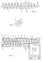
- 1 denotes a tube which forms the housing of a screw conveyor.
- the tube 1 is divided into a sieve part 1 'with bores (not shown here) and a press part 1''without passages.
- an open conveyor helix 2 In the interior of the tube 1 there is an open conveyor helix 2, without a shaft, which merges with a screw conveyor 3a, which is connected to a drive shaft 3 in the usual way.
- the straight pipe 1 is screwed to a pipe bend 4 via a flange connection F, while the shaft 3 leads straight out of this pipe bend 4 and is rotated clockwise (Md) via a gear 7 with drive motor 7a at approx. 5 revolutions per minute.
- the pipe bend 4 is connected to an intermediate piece 5 via a further flange connection F, which in turn is connected via a further flange F 'to an ejection tube 6 made of HPE (hard polyethylene).
- HPE hard polyethylene
- the rotating coil 2 conveys suspended parts, solids etc. into the interior of the pipe by means of its screw-like movement, conveys them in more or less large dirt parts S above the water level N and compresses them in the pipe elbow 5 to a complete plug, S ', which conveys successively upwards and is deposited in a container C.
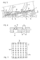
- the drainage takes place through the bores 1a shown in FIGS. 5 to 7.
- the flow of the purified water takes place through the bores 1a shown in more detail in FIGS. 6 to 7.
- the screenings are dewatered in the rear part of the tube 1, likewise through the same bores 1a which, however, are present at larger intervals, ie in smaller numbers, adapted to the water content of the screenings.
- the construction of the screw conveyor can be clearly seen in FIG. 2.
- On the shaft 3 is connected to this by welding seams the screw conveyor 3a and at the point A of the feed screw 2 is welded cantilevered.
- FIG. 4 the screenings are not deflected; this is conveyed horizontally and falls directly into a container C via a passage 12 '.
- the middle part of the channel 11 is configured in the same way as in FIG. 1, but ends in a lower lateral outlet 11' and has a base 11 '' on the inlet side. on.
- the tube 1 ' is here provided with conical tapering 12, the internal screw conveyor is adapted to this tapering and the sieve part 1' is longer compared to the embodiment of FIG. 1, because the still wet sieve material requires additional drainage due to the shorter conveying path.
- a thin guide shaft 13 can be seen in this variant, with an end-side ball bearing 14, which is fastened in a support 15 to a flange segment 16 on the tube 1 '.
- the drive, analogous to FIG. 1, is not shown here.
- the mode of operation and control is analogous to FIG. 1; the water dripping out over a longer path of the conveyor line is symbolized by vertical arrows.
- FIG. 5 shows the filter effect of the system using the example of cotton swabs 20. These are moved or “screwed up” by the conveyor spiral 2 in the direction of the arrow, and lifted out of the water and transported away accordingly. Due to the large number of holes 1a, the filtrate can easily drain off.
- the larger diameter D is 11.0 mm.
- a section of a part 1 'of the tube 1 can be seen.
- a total of 3000 bores were created in tube 1 by means of a numerically controlled machine tool.
- the conveying spiral 2 consists of a very abrasion-resistant high-alloy steel must be made.
- Manganese alloy steel (according to DIN 18703) has proven itself.
- a one-sided average play of 0.3 to 0.5 mm has also proven to be favorable.
- the low flow resistance of the system proves to be a particular advantage, so that a small gradient in channel 11 is sufficient, since the water inlet at the front, at the front of the pipe 1, is largely open.
- the embodiments carried out using the example of a fine rake in a sewage treatment plant are not restricted to this use.
- the test operation has shown here that the filtrate is on the one hand 100% free of larger solids and on the other hand that the entrained sand can be collected by settling in a subsequent sand basin without the screenings S 'intended for combustion being heavily contaminated with mineral substances.
- the device according to the invention enables a smaller dimensioning of sewage treatment plants and thus represents an economically valuable contribution to environmental protection. It can be adapted within wide limits to the intended use or the type of material to be screened, for example also by a targeted compression of the material to be screened, degressive change in the incline of the screw conveyor.
- the subject of the invention brings about a perfect mechanical purification of waste water and can also serve well in cases where no further clarification stages are connected.
Landscapes
- Chemical & Material Sciences (AREA)
- Chemical Kinetics & Catalysis (AREA)
- Hydrology & Water Resources (AREA)
- Health & Medical Sciences (AREA)
- Public Health (AREA)
- Water Supply & Treatment (AREA)
- Engineering & Computer Science (AREA)
- Life Sciences & Earth Sciences (AREA)
- Screw Conveyors (AREA)
- Treatment Of Sludge (AREA)
- Separation Of Solids By Using Liquids Or Pneumatic Power (AREA)
- Electrical Discharge Machining, Electrochemical Machining, And Combined Machining (AREA)
- Treatment Of Liquids With Adsorbents In General (AREA)
- Filtration Of Liquid (AREA)
Priority Applications (6)
| Application Number | Priority Date | Filing Date | Title |
|---|---|---|---|
| ES92200306T ES2088084T3 (es) | 1992-02-04 | 1992-02-04 | Dispositivo para la eliminacion de sustancias solidas de un liquido circulante, procedimiento para la explotacion del mismo asi como uso del dispositivo. |
| EP92200306A EP0554580B1 (fr) | 1992-02-04 | 1992-02-04 | Appareil pour la séparation de matières d'un liquide courant, méthode de fonctionnement et utilisation de cet appareil |
| DE59206317T DE59206317D1 (de) | 1992-02-04 | 1992-02-04 | Vorrichtung zum Entfernen von Feststoffen aus einer strömenden Flüssigkeit, Verfahren zu deren Betrieb sowie Verwendung der Vorrichtung |
| AT92200306T ATE137987T1 (de) | 1992-02-04 | 1992-02-04 | Vorrichtung zum entfernen von feststoffen aus einer strömenden flüssigkeit, verfahren zu deren betrieb sowie verwendung der vorrichtung |
| DE4302849A DE4302849A1 (fr) | 1992-02-04 | 1993-02-02 | |
| BE9300108A BE1006122A6 (fr) | 1992-02-04 | 1993-02-03 | Dispositif pour eliminer des matieres solides d'un liquide en ecoulement, procede pour son exploitation et utilisation de ce dispositif. |
Applications Claiming Priority (1)
| Application Number | Priority Date | Filing Date | Title |
|---|---|---|---|
| EP92200306A EP0554580B1 (fr) | 1992-02-04 | 1992-02-04 | Appareil pour la séparation de matières d'un liquide courant, méthode de fonctionnement et utilisation de cet appareil |
Publications (2)
| Publication Number | Publication Date |
|---|---|
| EP0554580A1 true EP0554580A1 (fr) | 1993-08-11 |
| EP0554580B1 EP0554580B1 (fr) | 1996-05-15 |
Family
ID=8210404
Family Applications (1)
| Application Number | Title | Priority Date | Filing Date |
|---|---|---|---|
| EP92200306A Expired - Lifetime EP0554580B1 (fr) | 1992-02-04 | 1992-02-04 | Appareil pour la séparation de matières d'un liquide courant, méthode de fonctionnement et utilisation de cet appareil |
Country Status (5)
| Country | Link |
|---|---|
| EP (1) | EP0554580B1 (fr) |
| AT (1) | ATE137987T1 (fr) |
| BE (1) | BE1006122A6 (fr) |
| DE (2) | DE59206317D1 (fr) |
| ES (1) | ES2088084T3 (fr) |
Cited By (6)
| Publication number | Priority date | Publication date | Assignee | Title |
|---|---|---|---|---|
| DE29614454U1 (de) * | 1996-08-21 | 1996-11-07 | Feierabend, Andreas, 45326 Essen | Vorrichtung zum Entfernen von Rechen- und/oder Siebgut aus einer in einem Gerinne strömenden Flüssigkeit |
| DE19600372C1 (de) * | 1996-01-08 | 1997-04-30 | Oeko Systeme Maschinen Und Anl | Vorrichtung zum Austragen von festen Verunreinigungen aus Abwasser |
| EP1018370A1 (fr) * | 1999-01-07 | 2000-07-12 | Franz Marx | Appareil pour le prétraitement mécanique des eaux usées |
| CN105645727A (zh) * | 2016-04-07 | 2016-06-08 | 广东绿由环保设备有限公司 | 一种污泥干化装置 |
| EP3477011A1 (fr) * | 2017-10-25 | 2019-05-01 | Huber SE | Dispositif et procédé de séparation et de transport de produit de filtrage à partir d'eaux usées |
| US12257533B2 (en) | 2021-01-19 | 2025-03-25 | Aqua Innovation Network Holding B.V. | Filtering device and system, method of installing a filtering device and use of a filtering device |
Families Citing this family (9)
| Publication number | Priority date | Publication date | Assignee | Title |
|---|---|---|---|---|
| DE4412124C2 (de) * | 1994-04-08 | 1997-04-30 | Huber Hans Gmbh Maschinen Und | Vorrichtung zum Entfernen von Abscheidegut aus in einem Gerinne strömender Flüssigkeit |
| DE4412679C2 (de) * | 1994-04-13 | 1997-03-06 | Hans Georg Huber | Siebvorrichtung für Zulaufbauwerke |
| AT402079B (de) * | 1995-03-03 | 1997-01-27 | Inowa Gmbh & Co Kg | Vorrichtung zum abscheiden grobkörniger feststoffe aus abwässern, insbesondere von schlachtbetrieben |
| DE19520992C2 (de) * | 1995-06-08 | 1999-08-12 | Premark Feg L L C N D Ges D St | Vorrichtung und Verfahren zum Entfernen von Abfällen aus Wasser |
| SE507499C2 (sv) * | 1996-10-07 | 1998-06-15 | Spirac Engineering Ab | Separationsanordning försedd med transportspiral och silorgan |
| AT404233B (de) * | 1997-02-10 | 1998-09-25 | Abz Zierler Ges M B H & Co Kg | Verfahren und vorrichtung zum waschen von rechengut |
| DE10030784B4 (de) * | 2000-06-29 | 2006-04-20 | Kilia-Fleischerei- Und Spezial-Maschinen Fabrik Gmbh | Einrichtung zum Entwässern von Feststoffen,die von Fluiden separiert sind |
| DE10100534B4 (de) * | 2001-01-05 | 2004-05-19 | Stefan Barth | Bahnkreisende, oszillierende, steigende Schiefe-Ebene |
| DE102019007315B3 (de) * | 2019-10-21 | 2020-11-05 | Stefan Barth | Kombirotationshebel mit Förderschnecke für kleine Wasserkraftwerke |
Citations (6)
| Publication number | Priority date | Publication date | Assignee | Title |
|---|---|---|---|---|
| FR529099A (fr) * | 1918-06-05 | 1921-11-23 | Hermann Plauson | Filtre-presse |
| CH484687A (de) * | 1969-01-24 | 1970-01-31 | Filtrox Maschb Ag | Filterkerze |
| DE3122131A1 (de) * | 1981-06-04 | 1982-12-23 | Günther 7913 Senden Abel | Vorrichtung zur entnahme und entwaesserung von feststoffen aus fluessigkeiten, insbesondere aus gerinnen von klaeranlagen |
| EP0225401A1 (fr) * | 1985-12-11 | 1987-06-16 | GEA Energietechnik GmbH & Co. | Procédé de séparation de particules d'impuretés solides de l'eau de refroidissement des centrales et similaires |
| EP0293515A2 (fr) * | 1987-05-16 | 1988-12-07 | Hans Georg Huber | Dispositif pour enlever des solides d'un liquide coulant dans un égout |
| DE3915529A1 (de) * | 1989-05-12 | 1990-11-15 | Noggerath & Co | Vorrichtung zum entfernen von rechen- und/oder siebgut aus einem gerinne stroemender fluessigkeiten |
-
1992
- 1992-02-04 ES ES92200306T patent/ES2088084T3/es not_active Expired - Lifetime
- 1992-02-04 DE DE59206317T patent/DE59206317D1/de not_active Expired - Fee Related
- 1992-02-04 AT AT92200306T patent/ATE137987T1/de not_active IP Right Cessation
- 1992-02-04 EP EP92200306A patent/EP0554580B1/fr not_active Expired - Lifetime
-
1993
- 1993-02-02 DE DE4302849A patent/DE4302849A1/de not_active Withdrawn
- 1993-02-03 BE BE9300108A patent/BE1006122A6/fr not_active IP Right Cessation
Patent Citations (6)
| Publication number | Priority date | Publication date | Assignee | Title |
|---|---|---|---|---|
| FR529099A (fr) * | 1918-06-05 | 1921-11-23 | Hermann Plauson | Filtre-presse |
| CH484687A (de) * | 1969-01-24 | 1970-01-31 | Filtrox Maschb Ag | Filterkerze |
| DE3122131A1 (de) * | 1981-06-04 | 1982-12-23 | Günther 7913 Senden Abel | Vorrichtung zur entnahme und entwaesserung von feststoffen aus fluessigkeiten, insbesondere aus gerinnen von klaeranlagen |
| EP0225401A1 (fr) * | 1985-12-11 | 1987-06-16 | GEA Energietechnik GmbH & Co. | Procédé de séparation de particules d'impuretés solides de l'eau de refroidissement des centrales et similaires |
| EP0293515A2 (fr) * | 1987-05-16 | 1988-12-07 | Hans Georg Huber | Dispositif pour enlever des solides d'un liquide coulant dans un égout |
| DE3915529A1 (de) * | 1989-05-12 | 1990-11-15 | Noggerath & Co | Vorrichtung zum entfernen von rechen- und/oder siebgut aus einem gerinne stroemender fluessigkeiten |
Non-Patent Citations (1)
| Title |
|---|
| WATER POLLUTION CONTROL FEDERATION AND AMERICAN SOCIETY OF CIVIL ENGINEERS 'WASTEWATER TREATMENT PLANT DESIGN' 1977 , LANCASTER PRESS INC. , LANCASTER, PA., USA * |
Cited By (11)
| Publication number | Priority date | Publication date | Assignee | Title |
|---|---|---|---|---|
| DE19600372C1 (de) * | 1996-01-08 | 1997-04-30 | Oeko Systeme Maschinen Und Anl | Vorrichtung zum Austragen von festen Verunreinigungen aus Abwasser |
| DE29614454U1 (de) * | 1996-08-21 | 1996-11-07 | Feierabend, Andreas, 45326 Essen | Vorrichtung zum Entfernen von Rechen- und/oder Siebgut aus einer in einem Gerinne strömenden Flüssigkeit |
| EP1018370A1 (fr) * | 1999-01-07 | 2000-07-12 | Franz Marx | Appareil pour le prétraitement mécanique des eaux usées |
| CN105645727A (zh) * | 2016-04-07 | 2016-06-08 | 广东绿由环保设备有限公司 | 一种污泥干化装置 |
| EP3477011A1 (fr) * | 2017-10-25 | 2019-05-01 | Huber SE | Dispositif et procédé de séparation et de transport de produit de filtrage à partir d'eaux usées |
| CN109707030A (zh) * | 2017-10-25 | 2019-05-03 | 汉斯琥珀欧洲公司 | 用来将筛选物从废水中分离和排出的结构和方法 |
| US10994230B2 (en) | 2017-10-25 | 2021-05-04 | Huber Se | Arrangement and method for separating out and removing screenings from wastewater |
| RU2770601C2 (ru) * | 2017-10-25 | 2022-04-18 | Хубер Се | Установка и способ для улавливания и удаления просеиваемого материала из технологической воды |
| EP3477011B1 (fr) | 2017-10-25 | 2023-11-01 | Huber SE | Dispositif et procédé de séparation et de transport de produit de filtrage à partir d'eaux usées |
| CN109707030B (zh) * | 2017-10-25 | 2025-01-10 | 汉斯琥珀欧洲公司 | 用来将筛选物从废水中分离和排出的结构和方法 |
| US12257533B2 (en) | 2021-01-19 | 2025-03-25 | Aqua Innovation Network Holding B.V. | Filtering device and system, method of installing a filtering device and use of a filtering device |
Also Published As
| Publication number | Publication date |
|---|---|
| ATE137987T1 (de) | 1996-06-15 |
| DE4302849A1 (fr) | 1993-08-05 |
| ES2088084T3 (es) | 1996-08-01 |
| DE59206317D1 (de) | 1996-06-20 |
| EP0554580B1 (fr) | 1996-05-15 |
| BE1006122A6 (fr) | 1994-05-17 |
Similar Documents
| Publication | Publication Date | Title |
|---|---|---|
| EP0554580B1 (fr) | Appareil pour la séparation de matières d'un liquide courant, méthode de fonctionnement et utilisation de cet appareil | |
| DE69524591T2 (de) | Vorrichtung und methoden zum abtrennen von feststoffen aus strömenden flüssigkeiten oder gasen | |
| EP0908569B1 (fr) | Dispositif de tamisage pour eaux usées dans une canalisation | |
| DE3019127C2 (de) | Vorrichtung zum Entfernen von Rechengut aus Zulaufgerinnen, insbesondere von Kläranlagen | |
| DE2925269A1 (de) | Abwasserklaervorrichtung | |
| EP0968039B1 (fr) | Dispositif de filtration avec lavage a contre-courant | |
| DE3122131C2 (de) | Vorrichtung zur Entnahme und Entwässerung von Feststoffen aus Flüssigkeiten, insbesondere aus Gerinnen von Kläranlagen | |
| DE2751091A1 (de) | Vorrichtung zum abtrennen von fluessigkeit aus einem schlammartigen brei oder gemenge | |
| DE2556995A1 (de) | Mischkammer zum eindicken einer trueben mittels eines flockungsmittels | |
| DE4328476C2 (de) | Vorrichtung zum Austragen von festen Bestandteilen aus einem Fluid | |
| EP0267149B1 (fr) | Procédé d'épuration d'un tamis rotatif et tamis rotatif | |
| EP1137469B1 (fr) | Dispositif de separation d'eau usee | |
| AT505926A4 (de) | Abwasserbehandlungsanlage und verfahren zum behandeln von abwasser | |
| EP1927388A1 (fr) | Système de filtre de réservoir des eaux pluviales | |
| DE3920196C2 (fr) | ||
| DE4213847A1 (de) | Geraet fuer die mechanische reinigung von fluessigkeiten in gerinnen oder in behaeltern | |
| DE3426742C2 (fr) | ||
| DE3342689A1 (de) | Filtervorrichtung zum entfernen von verunreinigungen aus fluessigkeiten, insbesondere aus dispersionsfarben | |
| DE4325584A1 (de) | Vorrichtung zur Rückhaltung von Schwimmstoffen an Überläufen von Regenentlastungsanlagen | |
| WO2000026141A1 (fr) | Installation compacte pour l'epuration mecanique d'eaux usees | |
| DE9302653U1 (de) | Waschanlage zum Reinigen von Fahrzeugreifen | |
| DE10030784B4 (de) | Einrichtung zum Entwässern von Feststoffen,die von Fluiden separiert sind | |
| DE9303867U1 (de) | Reinigungsvorrichtung zur Reinigung von in einem Gerinne fließendem Wasser | |
| DE102005019001A1 (de) | Siebvorrichtung zur Reinigung von Flüssigkeiten, Sammelbecken mit einer solchen Siebvorrichtung und Verfahren zur Reinigung von Flüssigkeiten | |
| EP0732458B1 (fr) | Dispositif pour l'élimination des particules solides d'une masse solide/liquide |
Legal Events
| Date | Code | Title | Description |
|---|---|---|---|
| PUAI | Public reference made under article 153(3) epc to a published international application that has entered the european phase |
Free format text: ORIGINAL CODE: 0009012 |
|
| AK | Designated contracting states |
Kind code of ref document: A1 Designated state(s): AT BE CH DE DK ES FR GB GR IT LI LU MC NL PT SE |
|
| 17P | Request for examination filed |
Effective date: 19940119 |
|
| 17Q | First examination report despatched |
Effective date: 19940506 |
|
| GRAA | (expected) grant |
Free format text: ORIGINAL CODE: 0009210 |
|
| AK | Designated contracting states |
Kind code of ref document: B1 Designated state(s): AT BE CH DE DK ES FR GB GR IT LI LU MC NL PT SE |
|
| PG25 | Lapsed in a contracting state [announced via postgrant information from national office to epo] |
Ref country code: IT Free format text: LAPSE BECAUSE OF FAILURE TO SUBMIT A TRANSLATION OF THE DESCRIPTION OR TO PAY THE FEE WITHIN THE PRE;WARNING: LAPSES OF ITALIAN PATENTS WITH EFFECTIVE DATE BEFORE 2007 MAY HAVE OCCURRED AT ANY TIME BEFORE 2007. THE CORRECT EFFECTIVE DATE MAY BE DIFFERENT FROM THE ONE RECORDED.SCRIBED TIME-LIMIT Effective date: 19960515 Ref country code: BE Effective date: 19960515 Ref country code: GB Effective date: 19960515 Ref country code: NL Free format text: LAPSE BECAUSE OF FAILURE TO SUBMIT A TRANSLATION OF THE DESCRIPTION OR TO PAY THE FEE WITHIN THE PRESCRIBED TIME-LIMIT Effective date: 19960515 Ref country code: DK Effective date: 19960515 Ref country code: GR Free format text: LAPSE BECAUSE OF FAILURE TO SUBMIT A TRANSLATION OF THE DESCRIPTION OR TO PAY THE FEE WITHIN THE PRESCRIBED TIME-LIMIT Effective date: 19960515 |
|
| REF | Corresponds to: |
Ref document number: 137987 Country of ref document: AT Date of ref document: 19960615 Kind code of ref document: T |
|
| REG | Reference to a national code |
Ref country code: CH Ref legal event code: NV Representative=s name: PPS POLYVALENT PATENT SERVICE AG |
|
| ET | Fr: translation filed | ||
| REF | Corresponds to: |
Ref document number: 59206317 Country of ref document: DE Date of ref document: 19960620 |
|
| REG | Reference to a national code |
Ref country code: ES Ref legal event code: BA2A Ref document number: 2088084 Country of ref document: ES Kind code of ref document: T3 |
|
| REG | Reference to a national code |
Ref country code: ES Ref legal event code: FG2A Ref document number: 2088084 Country of ref document: ES Kind code of ref document: T3 |
|
| PG25 | Lapsed in a contracting state [announced via postgrant information from national office to epo] |
Ref country code: SE Effective date: 19960815 |
|
| PG25 | Lapsed in a contracting state [announced via postgrant information from national office to epo] |
Ref country code: PT Effective date: 19960816 |
|
| NLV1 | Nl: lapsed or annulled due to failure to fulfill the requirements of art. 29p and 29m of the patents act | ||
| GBV | Gb: ep patent (uk) treated as always having been void in accordance with gb section 77(7)/1977 [no translation filed] |
Effective date: 19960515 |
|
| PGFP | Annual fee paid to national office [announced via postgrant information from national office to epo] |
Ref country code: AT Payment date: 19970203 Year of fee payment: 6 |
|
| PGFP | Annual fee paid to national office [announced via postgrant information from national office to epo] |
Ref country code: ES Payment date: 19970205 Year of fee payment: 6 |
|
| PG25 | Lapsed in a contracting state [announced via postgrant information from national office to epo] |
Ref country code: LU Free format text: LAPSE BECAUSE OF NON-PAYMENT OF DUE FEES Effective date: 19970228 |
|
| PLBE | No opposition filed within time limit |
Free format text: ORIGINAL CODE: 0009261 |
|
| STAA | Information on the status of an ep patent application or granted ep patent |
Free format text: STATUS: NO OPPOSITION FILED WITHIN TIME LIMIT |
|
| PGFP | Annual fee paid to national office [announced via postgrant information from national office to epo] |
Ref country code: CH Payment date: 19970415 Year of fee payment: 6 |
|
| PGFP | Annual fee paid to national office [announced via postgrant information from national office to epo] |
Ref country code: DE Payment date: 19970425 Year of fee payment: 6 |
|
| 26N | No opposition filed | ||
| PG25 | Lapsed in a contracting state [announced via postgrant information from national office to epo] |
Ref country code: MC Effective date: 19970831 |
|
| PGFP | Annual fee paid to national office [announced via postgrant information from national office to epo] |
Ref country code: FR Payment date: 19980130 Year of fee payment: 7 |
|
| PG25 | Lapsed in a contracting state [announced via postgrant information from national office to epo] |
Ref country code: AT Free format text: LAPSE BECAUSE OF NON-PAYMENT OF DUE FEES Effective date: 19980204 |
|
| PG25 | Lapsed in a contracting state [announced via postgrant information from national office to epo] |
Ref country code: ES Free format text: LAPSE BECAUSE OF NON-PAYMENT OF DUE FEES Effective date: 19980205 |
|
| PG25 | Lapsed in a contracting state [announced via postgrant information from national office to epo] |
Ref country code: CH Free format text: LAPSE BECAUSE OF NON-PAYMENT OF DUE FEES Effective date: 19980228 Ref country code: LI Free format text: LAPSE BECAUSE OF NON-PAYMENT OF DUE FEES Effective date: 19980228 |
|
| REG | Reference to a national code |
Ref country code: CH Ref legal event code: PL |
|
| PG25 | Lapsed in a contracting state [announced via postgrant information from national office to epo] |
Ref country code: DE Free format text: LAPSE BECAUSE OF NON-PAYMENT OF DUE FEES Effective date: 19981103 |
|
| PG25 | Lapsed in a contracting state [announced via postgrant information from national office to epo] |
Ref country code: FR Free format text: LAPSE BECAUSE OF NON-PAYMENT OF DUE FEES Effective date: 19991029 |
|
| REG | Reference to a national code |
Ref country code: FR Ref legal event code: ST |
|
| REG | Reference to a national code |
Ref country code: ES Ref legal event code: FD2A Effective date: 20000403 |