EP0293515A2 - Dispositif pour enlever des solides d'un liquide coulant dans un égout - Google Patents
Dispositif pour enlever des solides d'un liquide coulant dans un égout Download PDFInfo
- Publication number
- EP0293515A2 EP0293515A2 EP87117680A EP87117680A EP0293515A2 EP 0293515 A2 EP0293515 A2 EP 0293515A2 EP 87117680 A EP87117680 A EP 87117680A EP 87117680 A EP87117680 A EP 87117680A EP 0293515 A2 EP0293515 A2 EP 0293515A2
- Authority
- EP
- European Patent Office
- Prior art keywords
- grate
- conveyor
- bars
- section
- screenings
- Prior art date
- Legal status (The legal status is an assumption and is not a legal conclusion. Google has not performed a legal analysis and makes no representation as to the accuracy of the status listed.)
- Granted
Links
Images


Classifications
-
- E—FIXED CONSTRUCTIONS
- E03—WATER SUPPLY; SEWERAGE
- E03F—SEWERS; CESSPOOLS
- E03F5/00—Sewerage structures
- E03F5/14—Devices for separating liquid or solid substances from sewage, e.g. sand or sludge traps, rakes or grates
-
- B—PERFORMING OPERATIONS; TRANSPORTING
- B01—PHYSICAL OR CHEMICAL PROCESSES OR APPARATUS IN GENERAL
- B01D—SEPARATION
- B01D29/00—Filters with filtering elements stationary during filtration, e.g. pressure or suction filters, not covered by groups B01D24/00 - B01D27/00; Filtering elements therefor
- B01D29/01—Filters with filtering elements stationary during filtration, e.g. pressure or suction filters, not covered by groups B01D24/00 - B01D27/00; Filtering elements therefor with flat filtering elements
- B01D29/03—Filters with filtering elements stationary during filtration, e.g. pressure or suction filters, not covered by groups B01D24/00 - B01D27/00; Filtering elements therefor with flat filtering elements self-supporting
- B01D29/035—Filters with filtering elements stationary during filtration, e.g. pressure or suction filters, not covered by groups B01D24/00 - B01D27/00; Filtering elements therefor with flat filtering elements self-supporting with curved filtering elements
-
- B—PERFORMING OPERATIONS; TRANSPORTING
- B01—PHYSICAL OR CHEMICAL PROCESSES OR APPARATUS IN GENERAL
- B01D—SEPARATION
- B01D29/00—Filters with filtering elements stationary during filtration, e.g. pressure or suction filters, not covered by groups B01D24/00 - B01D27/00; Filtering elements therefor
- B01D29/44—Edge filtering elements, i.e. using contiguous impervious surfaces
- B01D29/445—Bar screens
-
- B—PERFORMING OPERATIONS; TRANSPORTING
- B01—PHYSICAL OR CHEMICAL PROCESSES OR APPARATUS IN GENERAL
- B01D—SEPARATION
- B01D29/00—Filters with filtering elements stationary during filtration, e.g. pressure or suction filters, not covered by groups B01D24/00 - B01D27/00; Filtering elements therefor
- B01D29/50—Filters with filtering elements stationary during filtration, e.g. pressure or suction filters, not covered by groups B01D24/00 - B01D27/00; Filtering elements therefor with multiple filtering elements, characterised by their mutual disposition
- B01D29/52—Filters with filtering elements stationary during filtration, e.g. pressure or suction filters, not covered by groups B01D24/00 - B01D27/00; Filtering elements therefor with multiple filtering elements, characterised by their mutual disposition in parallel connection
- B01D29/54—Filters with filtering elements stationary during filtration, e.g. pressure or suction filters, not covered by groups B01D24/00 - B01D27/00; Filtering elements therefor with multiple filtering elements, characterised by their mutual disposition in parallel connection arranged concentrically or coaxially
-
- B—PERFORMING OPERATIONS; TRANSPORTING
- B01—PHYSICAL OR CHEMICAL PROCESSES OR APPARATUS IN GENERAL
- B01D—SEPARATION
- B01D29/00—Filters with filtering elements stationary during filtration, e.g. pressure or suction filters, not covered by groups B01D24/00 - B01D27/00; Filtering elements therefor
- B01D29/62—Regenerating the filter material in the filter
- B01D29/64—Regenerating the filter material in the filter by scrapers, brushes, nozzles, or the like, acting on the cake side of the filtering element
- B01D29/6469—Regenerating the filter material in the filter by scrapers, brushes, nozzles, or the like, acting on the cake side of the filtering element scrapers
- B01D29/6476—Regenerating the filter material in the filter by scrapers, brushes, nozzles, or the like, acting on the cake side of the filtering element scrapers with a rotary movement with respect to the filtering element
-
- B—PERFORMING OPERATIONS; TRANSPORTING
- B01—PHYSICAL OR CHEMICAL PROCESSES OR APPARATUS IN GENERAL
- B01D—SEPARATION
- B01D29/00—Filters with filtering elements stationary during filtration, e.g. pressure or suction filters, not covered by groups B01D24/00 - B01D27/00; Filtering elements therefor
- B01D29/76—Handling the filter cake in the filter for purposes other than for regenerating
- B01D29/80—Handling the filter cake in the filter for purposes other than for regenerating for drying
- B01D29/82—Handling the filter cake in the filter for purposes other than for regenerating for drying by compression
- B01D29/828—Handling the filter cake in the filter for purposes other than for regenerating for drying by compression using screws
-
- B—PERFORMING OPERATIONS; TRANSPORTING
- B30—PRESSES
- B30B—PRESSES IN GENERAL
- B30B9/00—Presses specially adapted for particular purposes
- B30B9/02—Presses specially adapted for particular purposes for squeezing-out liquid from liquid-containing material, e.g. juice from fruits, oil from oil-containing material
- B30B9/12—Presses specially adapted for particular purposes for squeezing-out liquid from liquid-containing material, e.g. juice from fruits, oil from oil-containing material using pressing worms or screws co-operating with a permeable casing
- B30B9/128—Vertical or inclined screw presses
-
- E—FIXED CONSTRUCTIONS
- E02—HYDRAULIC ENGINEERING; FOUNDATIONS; SOIL SHIFTING
- E02B—HYDRAULIC ENGINEERING
- E02B5/00—Artificial water canals, e.g. irrigation canals
- E02B5/08—Details, e.g. gates, screens
-
- E—FIXED CONSTRUCTIONS
- E02—HYDRAULIC ENGINEERING; FOUNDATIONS; SOIL SHIFTING
- E02B—HYDRAULIC ENGINEERING
- E02B8/00—Details of barrages or weirs ; Energy dissipating devices carried by lock or dry-dock gates
- E02B8/02—Sediment base gates; Sand sluices; Structures for retaining arresting waterborne material
Definitions
- the invention relates to a device for removing screenings and / or screenings from liquid flowing in a channel, with an up to the bottom of the channel, which is arranged obliquely and not driven, partially immersed in the liquid, cylindrical jacket-shaped grate that extends above the grate height has continuous grate bars and longitudinal gaps formed between them and into an obliquely upward directed, leading to a discharge point and designed as a screw conveyor with housing, shaft and conveyor helix conveyor for the screenings, the conveyor coil along the grate bars decreases the screenings, conveys upwards and so the rust cleans again and again.
- This device can be used in particular in sewage treatment plants, but can also be used advantageously for other areas of technology, for example in the textile industry, the plastics industry and the like.
- the device will be used in particular when small channel widths of the order of 100 to 500 mm are present and / or small gap widths are required in order to separate and convey fine screenings.
- a device of the type described above is known from DE-OS 21 42 540.
- This device consists essentially of a screw conveyor, housing, shaft and conveyor helix, with an attached motor being provided which transmits its rotary drive to the shaft and thus to the conveyor helix.
- the housing of the screw conveyor is completely replaced in its lower area, which plunges into the water level, by the grate, which consists of grate bars that pass through the grate height, between which longitudinal gaps are formed, which thus run parallel to the axis of the shaft on the cylindrical circumference.
- the grate bars have no transverse support within the grate and have an essentially rectangular cross section, the long side of this rectangular cross section being arranged in the radial direction from the shaft.
- the passage cross-section in the case of grate bars arranged and designed in this way widens in the direction of passage, i.e. radially to the axis of the shaft, only in proportion to the radius, that is to say comparatively little, so that here too there is a risk that screenings which have passed through the narrowest point of the grate can enter the Longitudinal gaps settled, wedged and thus also permanently reduced the free grate surface, the rest of the hydraulic resistance of the grate then also increasing.
- H. filamentous screenings accumulate, forming a plait, at the delimitation points of the holes and in this way blocks the passage cross-section for the liquid. So there are no longitudinal gaps in the longitudinal direction, but at each end of an elongated slot, in connection with the rotating conveyor helix, a pair of scissors or a cutting device is created, which acts in such a way that separated material is only partially conveyed away by the conveyor helix, while a large part of the separated screenings is simply cut off and then passes through the elongated slots on the part of the liquid that has been cleaned per se.
- the invention has for its object to develop a device of the type described in such a way that on the one hand the gap width remains reliably constant and on the other hand the disadvantages of a cutting effect are largely avoided, so that not only a reliable separation effect is achieved with repeatedly cleaned rust, but also the hydraulic resistance of the grate is kept low over long operating times.
- the grate bars have an approximately triangular or trapezoidal cross section with rounded edges and are arranged such that a triangular or trapezoidal side of the cross section is tangent to the circumferential direction of the conveying spiral and, furthermore, a narrowest point of the longitudinal gaps is as small as possible Radius and then a disproportionately widening free cross section of the longitudinal gaps in the direction of flow of the liquid results, and that the grate bars forming the longitudinal gaps are connected to one another on the outside by support bars.
- the narrowest point of the longitudinal gaps is advantageously arranged on the smallest possible radius, that is as close as possible to the contact point with the outer circumference of the conveying spiral, so that its stripping effect can have a full effect here.
- the cleaning effect is therefore particularly great and the hydraulic resistance of the grate remains consistently low over the operating time due to the recurring, very effective cleaning.
- the rounded edges are also important insofar as a cutting and shearing effect in connection with the contact of the conveying spiral is thus avoided.
- fibrous or thread-like screenings are drawn around these edges and in this way the separating effect is increased without a cutting effect. Despite this good separation effect, it cannot be avoided that a small proportion of the screenings can also pass through the longitudinal gaps.
- this screenings cannot settle in the longitudinal gaps, because here the cross section increases disproportionately, ie to a greater extent than the radius from the axis of the shaft. In a cross section that enlarges in this way, there is no separation effect outside the narrowest point.
- the triangular or trapezoidal cross-sectional shape of the grate bars is also advantageous insofar as the cross section is used in a way that is suitable for the stresses, for example in contrast to a rectangular cross section of the grate bars in which the long side is arranged in the radial direction.
- this cross-sectional design enables simple and precise manufacture position of the grate by making the contact points between the grate bars and the support bars relatively small, which is conducive to a precise welded connection of the parts to one another.
- the disproportionate increase in the free cross-section in the flow direction that is to say radially to the axis of the shaft of the screw conveyor device, is also advantageous in that the separation performance is improved because a large expansion of the free cross-section leads to a strong reduction in the flow speed and thus the risk is reduced that filamentous screenings are detached from the narrowest cross-sectional area by the free cross-sections and pass into the cleaned part of the liquid.
- the inventive design of the device can also be used advantageously when there are small channel widths, i.e.
- the device according to the invention also has considerable variability in the gap width. This can be changed from approx. 0.25 mm to 5 mm or beyond, without leaving the working principle of the device.
- the cross section of the grate bars can be formed symmetrically to the direction of flow of the liquid, the arrangement of course also being made in this way.
- the cross section can have the shape of an isosceles triangle, the smaller angle of the cross section at the tip of the isosceles triangle facing outwards.
- the support rods can also have a triangular or trapezoidal cross-section and be arranged so that the largest cross-sectional width points outward in the direction of flow.
- the cross sections of the grate bars on the one hand and the support bars on the other hand are thus arranged and provided in the opposite direction, so that there are surface-like parts on the inside of the grate and on the outside of the grate, which on the one hand are useful for the interaction of the conveyor helix or on the other hand a connection between grate bars and support bars, for example by welding.
- the grate bars and the support bars can also have approximately the same cross-section, i. H. the grate can ultimately be created from material with an identical cross-sectional shape.
- the grate can ultimately be created from material with an identical cross-sectional shape.
- it is by no means disadvantageous if a different cross-sectional shape is also used here, for example in order to promote stability in a special way.
- the side of the support rods facing the direction of flow is as small as possible, so that starting points or edges for the formation of braids are avoided.
- the support rods can be arranged at such a distance from one another on the circumference of the cylindrical grate that corresponds approximately to ten times the maximum width of the grate rods. This gives the grate a lattice-like appearance, whereby continuous longitudinal gaps are nevertheless created in the direction of the cylinder jacket of the grate. that are not interrupted at any point in this direction.
- the large number of connection points between the grate bars and the support bars gives the grate a defined shape of high precision, in particular in the area of the inner surface which comes into sliding contact with the outer circumference of the conveyor spiral. This is desirable or a prerequisite for good separation performance.
- the shaft of the screw conveyor device can only be provided in the region of the conveyor section adjoining the grate upwards: d. H.
- the shaft is missing and the torque is only transmitted via the conveyor spiral itself in this area.
- This design has an advantageous effect, in particular at high flow velocities, because the shaft, which would lead to vortex formation before the screenings are deposited, is missing.
- the reduction in cross-section through the shaft is avoided at this point.
- the grate made of grate bars and support bars can be designed to be open at the end at its lower end. A front plate usually provided there can therefore be missing and an otherwise necessary sole crack is avoided at this point. This is advantageous insofar as the lack of the end plate also eliminates the swirling of the liquid to be cleaned which is caused by it, so that this measure also flows against the grate evenly and without large eddy formation. This in turn favors the separation effect.
- the screw conveyor of the screw conveyor can be freely cantilevered at its lower end and supported above the grate by one or more plain bearing rings. This avoids storing the screw conveyor below the water level.
- the plain bearing rings can be arranged above the water level, expediently in the area in which the screw conveyor has a reduced diameter.
- the part of the conveyor helix that comes into contact with the grate bars of the grate can be designed to be elastic on its outer circumference. This serves to bridge inaccuracies in production, which is due to the special training the grate from grate bars and support bars - are already small, but cannot be avoided in principle. Due to this elastic design, there is no risk of build-up in the area of the grate, but this is cleaned again and again by the reliable contact of the conveyor spiral with the grate, so that the hydraulic resistance of the grate remains low.
- the conveyor spiral can be provided on its outer circumference with a bristle strip, an elastic wiper lip or the like. The elastic formation is realized by these elements. It can be seen that the restoring forces and the restoring speed of such an elastic material are quite sufficient to ensure the continuous contact during the rotary drive of the conveyor spiral to the grate or the grate bars.
- housing-like inlet walls can be provided, the grate being stably supported by these continuous, that is to say closed, inlet walls and even being additionally stabilized. In particular, it counteracts twisting of the grate and, on the other hand, allows a sealing strip to be properly designed and arranged with respect to the channel wall.
- the conveyor spiral passing over the area of the grate and the subsequent conveying section can have a larger outer diameter in the area of the grate than in the area of the adjoining conveying section, the grate being arranged on a correspondingly larger diameter than the housing of the screw conveyor device. Due to this design, the diameter of the grate is largely independent of the diameter of the conveyor section, where a compacting effect in the area of the conveyor section is achieved by this jump in diameter and, on the other hand, it is possible to select the area of the grate comparatively large even when the liquid screenings are loaded with screenings in varying degrees.
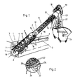
- the device is arranged with its axis 2 - inclined, that is to say neither horizontally nor vertically, in such a way that part of it adjoins side walls 3 of the channel 1, in which a water level 4 is in front of the device and a lower water level after the device, so that the channel 1 is flowed through in the direction of an arrow 6.
- the device has in its lower part a grate 7 which extends parallel to the axis 2 at least over such a height that the part engaging under the water level 4 is always in the water and different water levels are also taken into account.
- the grate 7 consists essentially of grate bars 8, which are arranged parallel to the axis 2 on the surface line of a cylinder, and of support bars 9, which extend over a cylinder segment tangential to the circumference of the cylinder of the grate bars 8 and thus perpendicular to the axis 2 . It goes without saying that the support rods 9 are arranged continuously over the circumferential surface of the grate 7 to the other side, although this is not shown for reasons of clarity.
- the support rods 9 are of a larger diameter than the grate rods 8, seen from the axis 2, so that continuous and uninterrupted longitudinal slots 10 are formed between the grate rods 8 parallel to the axis 2.
- the grate 7 can have an end plate 11 at its lower end which, in addition to the support rods 9, stabilizes the grate rods 8 and holds them in place.
- a housing 12 of a screw conveyor 13 is provided as a cylindrical outer surface.
- a shaft 15 is arranged, which is connected to or carries a conveyor helix 16, which extends over the entire length of the device and also projects into the part of the device in which the grate 7 is arranged.
- the shaft 15 is not provided or arranged there and the conveyor spiral 16 has a larger diameter which is adapted to the inner diameter of the grate bars 8.
- the lower end of the conveyor spiral 16 can be mounted in a bearing 17 in the region of the end plate 13. At the upper end of the housing 12, a further bearing, not shown here, is provided.
- the conveyor spiral 16 can have a non-constant gradient over its axial length.
- the slopes can be designed differently in some areas, or, as shown, a compacting zone 20 can be formed at the upper end of the conveying section, in the area of which the conveying helix has a smaller slope.
- the housing 12 is also double-walled, the inner wall part having openings so that, when the screenings are compacted or compressed, separated liquid can be led back into the channel 1 via a pipe 21, while the compacted screenings 22 can be guided via a chute 23 is dropped into a container 24.
- the grate bars 8 have an approximately triangular cross-section, in this case in the form of an isosceles triangle, one triangular side 25 being arranged tangentially to the inner circumference of the grate 7, so that the tip of the triangle is from seen from the axis 2 extends radially outwards.
- the continuous longitudinal slots 10 are formed between the grate bars 8, which have the narrowest points 26, which are provided due to the only rounded edges of the triangular cross section of the grate bars 8 close to the inner circumference, that is, following the triangular sides 25.
- the screenings 22 are deposited, as it were, on the inside of the grate 7, while the water passing through the grate 7 has a disproportionately widening cross section 28 following the narrowest points 26 according to the arrows 27. Because of this disproportionately,. H. itself stronger than the increase in the radius of this. Instead of the cross section corresponding to the axis 2, the flow velocity is reduced according to the arrows 27, which is reduced to a very great extent, so that the liquid flowing through does not have the possibility of pulling the separated screenings 22 through the longitudinal slots 10.
- the screenings 22 remain in the separated position and, when driving the conveyor spiral 16, is removed from its outer edge, grasped and guided upwards on the inside of the grate 7, in which case it then enters the area of the housing 12 and thus the conveyor path thereof Screw conveyor device 13 arrives in order to be finally compacted and dropped into the container 24.
- the support rods 9 supporting the grate bars 8 are not shown for the sake of clarity. Of course, these support rods 9 are present, since they form an essential element for the stabilization of the grate 7, so that the grate rods 8 cannot bend even when hard screenings occur, so that the gap width of the longitudinal slots 10 is kept constant. Thus, the separation security is maintained over the operating time and on the other hand no hard objects such as stones and. Like, clamped between the grate bars 8. The passage surfaces of the grate 7 are not blocked in this way.
- FIGS. 3 and 4 The embodiment of the device according to FIGS. 3 and 4 is constructed in a manner similar to that of the embodiments of FIGS. 1 and 2. Only the shaft 15 is continuously provided here, that is, it also extends in the area of the grate 7 and carries the conveyor spiral 16 here.
- Figure 4 clearly shows that the support bars 9 are arranged on a larger diameter than the grate bars 8, so that the arrangement of the support bars 9 do not affect the longitudinal slots 10 between the grate bars 8 and do not interrupt. It can be seen from FIG. 4 and also from FIG. 3 that the grate 7 is surrounded by housing-like inlet walls 29, so that the grate 7 is thereby additionally stabilized.
- the lower bearing 17 may also be missing in this embodiment.
- FIGS. 3 and 4 also illustrate the mutual spacing of the support bars 9 in relation to the design and arrangement of the grate bars 8.
- the support rods 9 can also have an approximately triangular or trapezoidal cross section, but are arranged in the opposite direction to the cross section of the grate rods 8.
- FIG. 5 shows a section shows. There is shown a section approximately perpendicular to the axis 2 of the device, so that the cross-sectional shape and arrangement of the grate bars 8 and the support bars 9 are particularly well recognizable in their mutual association.
- a cross section 31 of the support rods 9 is shown here for the sake of clarity.
- the two tips of the triangular cross sections face each other, so that here a relatively small contact surface is created, so that the grate bars 8 and the support bars 9 can advantageously be connected to one another by a welded connection under pressure, a large number of connection points being created and on the other hand, the diameter and the arrangement of the triangular sides 25 on their diameter are not is affected. From this illustration, the narrowest point 26 and the widening cross section 28 adjoining it can also be seen, each viewed in the flow direction 32 of the liquid, ie radially to the axis 2 or in the direction of the arrow 27.
- FIGS. 6 and 7 show two sectional representations approximately perpendicular to the axis 2 of the device in order to clarify the manner in which the contact between the conveyor spiral 16 and the grate 7 can be improved even further.
- the conveyor helix 16 has an outer edge 33 which faces the triangular sides 25 of the grate bars 8 of the grate 7.
- a dovetail-shaped groove 34 is expediently incorporated into this surface, in which a bristle strip 35 (FIG. 6) or a wiping lip 37 (FIG. 7) are embedded.
- the squeegee 36 is advantageously designed as a soft but abrasion-resistant plastic profile.
- the restoring force of the bristles of the bristle strip 35 or the elasticity of the wiping lip 36 ensures that, during circulation, the conveyor spiral 16 remains in contact with the triangular sides 25 of the grate bars 8 at any point on the circumference and reliably wipes off the screenings deposited there, conveying them upwards and in this way cleans the grate 7 continuously.
Landscapes
- Engineering & Computer Science (AREA)
- Chemical Kinetics & Catalysis (AREA)
- Chemical & Material Sciences (AREA)
- Mechanical Engineering (AREA)
- General Engineering & Computer Science (AREA)
- Life Sciences & Earth Sciences (AREA)
- Hydrology & Water Resources (AREA)
- Public Health (AREA)
- Water Supply & Treatment (AREA)
- Health & Medical Sciences (AREA)
- Structural Engineering (AREA)
- Civil Engineering (AREA)
- Filtration Of Liquid (AREA)
- Belt Conveyors (AREA)
- Separation Of Solids By Using Liquids Or Pneumatic Power (AREA)
- Electrical Discharge Machining, Electrochemical Machining, And Combined Machining (AREA)
- Chain Conveyers (AREA)
- Cleaning By Liquid Or Steam (AREA)
- Control And Other Processes For Unpacking Of Materials (AREA)
- Detergent Compositions (AREA)
- Cyclones (AREA)
- Physical Water Treatments (AREA)
- Heterocyclic Carbon Compounds Containing A Hetero Ring Having Nitrogen And Oxygen As The Only Ring Hetero Atoms (AREA)
- Pharmaceuticals Containing Other Organic And Inorganic Compounds (AREA)
- Medicines Containing Plant Substances (AREA)
- Paper (AREA)
Priority Applications (1)
| Application Number | Priority Date | Filing Date | Title |
|---|---|---|---|
| AT87117680T ATE79144T1 (de) | 1987-05-16 | 1987-11-30 | Vorrichtung zum entfernen von rechen- und /oder siebgut aus in einem gerinne stroemender fluessigkeit. |
Applications Claiming Priority (2)
| Application Number | Priority Date | Filing Date | Title |
|---|---|---|---|
| DE3716434A DE3716434C1 (de) | 1987-05-16 | 1987-05-16 | Vorrichtung zum Entfernen von Rechen- und/oder Siebgut aus in einem Gerinne stroemender Fluessigkeit |
| DE3716434 | 1987-05-16 |
Publications (3)
| Publication Number | Publication Date |
|---|---|
| EP0293515A2 true EP0293515A2 (fr) | 1988-12-07 |
| EP0293515A3 EP0293515A3 (en) | 1989-04-26 |
| EP0293515B1 EP0293515B1 (fr) | 1992-08-05 |
Family
ID=6327701
Family Applications (1)
| Application Number | Title | Priority Date | Filing Date |
|---|---|---|---|
| EP87117680A Expired - Lifetime EP0293515B1 (fr) | 1987-05-16 | 1987-11-30 | Dispositif pour enlever des solides d'un liquide coulant dans un égout |
Country Status (12)
| Country | Link |
|---|---|
| US (1) | US4859322A (fr) |
| EP (1) | EP0293515B1 (fr) |
| JP (1) | JPS63293213A (fr) |
| KR (1) | KR960008706B1 (fr) |
| AT (1) | ATE79144T1 (fr) |
| BR (1) | BR8800872A (fr) |
| CA (1) | CA1330957C (fr) |
| DE (1) | DE3716434C1 (fr) |
| DK (1) | DK44488A (fr) |
| ES (1) | ES2033780T3 (fr) |
| GR (1) | GR3005501T3 (fr) |
| PT (1) | PT86658B (fr) |
Cited By (6)
| Publication number | Priority date | Publication date | Assignee | Title |
|---|---|---|---|---|
| EP0389789A3 (en) * | 1989-03-31 | 1990-11-14 | Hans-Georg Huber | Device for removing solids from liquids flowing in a gutter |
| WO1991013672A3 (fr) * | 1990-03-06 | 1991-12-12 | Abel Guenther | Appareil servant a separer les liquides des solides |
| EP0554580A1 (fr) * | 1992-02-04 | 1993-08-11 | Fuchs Maschinenbau | Appareil pour la séparation de matières d'un liquide courant, méthode de fonctionnement et utilisation de cet appareil |
| EP0565898A1 (fr) * | 1992-04-07 | 1993-10-20 | Hans Georg Huber | Dispositif pour séparer des produits solides d'un liquide avec une surface de séparation cylindrique, perméable à ces liquides et pour l'enlèvement des produits solides |
| CN101979784A (zh) * | 2010-04-27 | 2011-02-23 | 孙光斌 | 螺旋离心式挖孔清淤机 |
| AT515053A1 (de) * | 2013-10-28 | 2015-05-15 | Ernst Ing Kurri | Anordnung zur Befüllung eines Silos |
Families Citing this family (60)
| Publication number | Priority date | Publication date | Assignee | Title |
|---|---|---|---|---|
| DE3915528C1 (en) * | 1989-05-12 | 1990-12-13 | Noggerath & Co, 3061 Ahnsen, De | Screw conveyor with material moisture reduction - has spiral brush in grate region, matching pitch of conveyor screw |
| DE3920196A1 (de) * | 1989-06-21 | 1991-01-10 | Huber Hans Georg Dipl Ing | Vorrichtung zum entfernen von rechen- und/oder siebgut aus in einem gerinne stroemender fluessigkeit |
| US5006236A (en) * | 1989-09-25 | 1991-04-09 | Hallco Fabricators, Inc. | Contaminant entrained flow separating apparatus |
| US5110461A (en) * | 1990-09-05 | 1992-05-05 | Abel Guenther | Apparatus for separating liquids and solids |
| FI87186C (fi) * | 1990-11-19 | 1992-12-10 | Ekotuotanto Ab Oy | Skruvgaller |
| DE4120846A1 (de) * | 1991-06-25 | 1993-01-14 | Ibo W Grimmel Abwassertechnik | Vorrichtung zur vorbehandlung von stark verschmutztem abwasser |
| DE4143376C2 (de) * | 1991-06-28 | 1994-12-15 | Hans Georg Huber | Kompaktanlage zum Abscheiden und Entfernen von Rechengut und Sand aus Zulaufgerinnen |
| DE4138825C2 (de) * | 1991-11-26 | 1994-02-10 | Huber Hans Gmbh | Vorrichtung zum Entfernen von Rechen- und/oder Siebgut aus in einem Gerinne strömender Flüssigkeit |
| JPH0710440B2 (ja) * | 1992-02-21 | 1995-02-08 | アムコン株式会社 | 固液分離装置 |
| DE4211659C2 (de) * | 1992-04-07 | 1996-03-28 | Hans Georg Huber | Vorrichtung zum Entfernen von Abscheidegut aus einerFlüssigkeit mit einer zylindermantelförmigen, flüssigkeitsdurchlässigen Abscheidefläche |
| DE4235903C2 (de) * | 1992-10-23 | 1995-05-24 | Hans Georg Huber | Vorrichtung zum Entfernen von Abscheidegut aus einer in einem Gerinne strömender Flüssigkeit |
| DE4237123C2 (de) * | 1992-11-03 | 1995-02-16 | Hans Georg Huber | Vorrichtung zum Reinigen großer Wassermengen von Rechengut |
| DE4320678C2 (de) * | 1993-06-22 | 1996-04-11 | Branko Dipl Ing Klasnic | Vorrichtung zum Entfernen von Rechengut aus einer mit einer verunreinigten Flüssigkeit durchströmten Zulaufrinne, insbesondere von Kläranlagen |
| DE4328476C2 (de) * | 1993-08-24 | 1997-10-30 | Rudolf Bischof Gmbh Tech Hande | Vorrichtung zum Austragen von festen Bestandteilen aus einem Fluid |
| DE4407525C1 (de) * | 1994-03-07 | 1995-11-02 | Spirac Engineering Ab | Vorrichtung zum Trennen von Feststoffen aus einer Flüssigkeit |
| DE4419612A1 (de) * | 1994-06-03 | 1995-12-07 | Noggerath Holding Gmbh Co Kg | Spiralförderer |
| DE9410097U1 (de) * | 1994-06-22 | 1994-08-11 | Basika Entwässerungen GmbH, 42111 Wuppertal | Fettabscheidevorrichtung |
| DE19508894A1 (de) * | 1995-03-11 | 1996-10-10 | Egner Andrea | Vorrichtung zur Entnahme von Feststoffen aus einer Flüssigkeit-Feststoffmasse |
| DE19520992C2 (de) * | 1995-06-08 | 1999-08-12 | Premark Feg L L C N D Ges D St | Vorrichtung und Verfahren zum Entfernen von Abfällen aus Wasser |
| DE29511462U1 (de) * | 1995-07-15 | 1995-09-28 | Hans Huber AG Maschinen- und Anlagenbau, 92334 Berching | Vorrichtung zum Entfernen von Abscheidegut aus einer in einem Gerinne strömenden Flüssigkeit |
| US5540844A (en) * | 1995-07-21 | 1996-07-30 | Meylor; Donald M. | Dewatering system |
| AUPN817896A0 (en) * | 1996-02-21 | 1996-03-14 | Nicholas, Douglas Ian | Stormwater sediment and litter trap |
| US5770094A (en) * | 1996-10-01 | 1998-06-23 | Johnson Machine Works, Inc. | Screw conveyor screening apparatus for removing solids from wastewater |
| FR2754812B1 (fr) * | 1996-10-17 | 1998-12-04 | Poitevine De Filtration Soc | Appareil d'epaississement de boues de station d'epuration et de separation liquide/solide |
| DE19744524C2 (de) * | 1997-10-09 | 2003-11-20 | Hans Huber Ag Masch & Anlagenb | Siebvorrichtung für in einem Zulaufrohr ankommendes Abwasser |
| US5980740A (en) * | 1998-01-06 | 1999-11-09 | Civitas Erosion Services, Inc. | Storm drain collection box filtration system |
| NO310454B1 (no) * | 1999-04-21 | 2001-07-09 | Harry Simonsen | Anordning for utskilling av forurensing fra vaskevann fra en vaskeanordning for notposer til merder |
| DE29920552U1 (de) | 1999-11-23 | 2000-02-17 | Klasnic, Branko, Dipl.-Ing., 81925 München | Vorrichtung zum Entfernen von Rechengut aus einem durchströmten Gerinne |
| DE10030784B4 (de) * | 2000-06-29 | 2006-04-20 | Kilia-Fleischerei- Und Spezial-Maschinen Fabrik Gmbh | Einrichtung zum Entwässern von Feststoffen,die von Fluiden separiert sind |
| DE60126292T2 (de) * | 2000-08-29 | 2007-05-31 | Hydro International Plc, Clevedon | Siebanordnung für eine überlaufschwelle für einen schmutzwasserkanal |
| DE10100534B4 (de) * | 2001-01-05 | 2004-05-19 | Stefan Barth | Bahnkreisende, oszillierende, steigende Schiefe-Ebene |
| NZ513379A (en) * | 2001-08-07 | 2004-03-26 | Power Glides Screens Ltd | Suspension screen raking system (NO.2) |
| US7350964B2 (en) * | 2003-03-04 | 2008-04-01 | Lothar Wellenbrock | Device for circulating grain products |
| DE10316173B4 (de) * | 2003-04-04 | 2006-03-16 | Hans Huber Ag Maschinen- Und Anlagenbau | Vorrichtung zum Entfernen von feinem Siebgut aus einer Flüssigkeit |
| ITMO20060207A1 (it) * | 2006-06-27 | 2007-12-28 | Wam Spa | Coclea da utilizzarsi per trasportatori, compattatori e simili. |
| JP4753911B2 (ja) * | 2007-04-27 | 2011-08-24 | 中国電力株式会社 | 除塵機 |
| JP4524351B2 (ja) | 2008-02-01 | 2010-08-18 | 三菱重工業株式会社 | バイオマス原料を用いた有機原料の製造システム及び方法 |
| JP4427583B2 (ja) | 2008-02-01 | 2010-03-10 | 三菱重工業株式会社 | バイオマスの水熱分解装置及び方法、バイオマス原料を用いた有機原料の製造システム |
| KR100941923B1 (ko) * | 2008-02-13 | 2010-02-11 | 주식회사 한성환경기연 | 스컴 스크린용 무축 스크류 컨베이어의 브러쉬 설치구조 |
| DE102008046928A1 (de) * | 2008-09-12 | 2010-03-18 | Georg Klaß sen. | Schneckenfilterpresse |
| GB2474688B (en) * | 2009-10-23 | 2014-05-07 | M & N Electrical And Mechanical Services Ltd | Separating apparatus |
| CA2741602C (fr) | 2010-03-10 | 2013-04-30 | Mitsubishi Heavy Industries, Ltd. | Appareil de decomposition hydrothermale de biomasse, methode de regulation de la temperature connexe et systeme de production de materiau organique brut utilisant le materiau de biomasse |
| BRPI1006883B1 (pt) | 2010-03-10 | 2021-06-29 | Mitsubishi Power Environmental Solutions, Ltd. | Equipamento de decomposição hidrotérmica de biomassa, método de controle de temperatura da mesma, e sistema de produção de matéria-prima orgânica usando material de biomassa |
| JP5854586B2 (ja) | 2010-07-06 | 2016-02-09 | 三菱重工メカトロシステムズ株式会社 | 糖液を用いた発酵システム及び方法 |
| WO2012004895A1 (fr) | 2010-07-09 | 2012-01-12 | 三菱重工業株式会社 | Système de traitement de biomasse et méthode de production de solution de sucre à l'aide d'une charge d'alimentation constituée de biomasse |
| BRPI1009203B1 (pt) | 2010-07-09 | 2020-10-06 | Mitsubishi Hitachi Power Systems Environmental Solutions, Ltd. | Sistema de decomposição hidrotérmica da biomassa e método de produção da solução de sacarídeo empregando material de biomassa |
| DE102010038417A1 (de) | 2010-07-26 | 2012-01-26 | Huber Se | Vorrichtung und Verfahren zum Entfernen von Siebgut aus einer Flüssigkeit |
| CA2744522C (fr) * | 2010-09-03 | 2014-07-29 | Mitsubishi Heavy Industries, Ltd. | Appareil poour decomposition de biomasse et methode connexe, systeme de production de solution de sucre au moyen de cette biomasse |
| ITBO20100093U1 (it) * | 2010-09-15 | 2012-03-16 | Cms Spa | Compattatore di rifiuti, di costruzione semplificata e di piccole dimensioni, particolarmente per bar, tavole calde od altri piccoli esercizi di ristorazione. |
| WO2012095976A1 (fr) | 2011-01-13 | 2012-07-19 | 三菱重工メカトロシステムズ株式会社 | Dispositif pour produire une solution de sucre, procédé de fermentation, procédé de production de solution de sucre et procédé de fermentation |
| KR101133112B1 (ko) * | 2011-07-29 | 2012-04-06 | 제천시 | 슬러지, 유분, 협잡물 종합 탈수 처리 장치 |
| JP5425348B1 (ja) | 2012-03-29 | 2014-02-26 | 三菱重工メカトロシステムズ株式会社 | バイオマスの処理システム、バイオマス原料を用いた糖液生産方法、アルコール製造方法 |
| CN103568353B (zh) * | 2012-07-20 | 2015-09-30 | 北京天高智机技术开发公司 | 一种餐厨垃圾浆渣分离机 |
| JP6138029B2 (ja) * | 2013-11-18 | 2017-05-31 | 日立造船株式会社 | ダム貯水池の堆砂排出設備 |
| WO2019150168A1 (fr) * | 2018-02-01 | 2019-08-08 | Universidad Tecnológica De Panamá (Utp) | Appareil pour la collecte de résidus solides à partir d'un débit d'eau |
| US10968617B2 (en) * | 2019-06-04 | 2021-04-06 | Terry Duperon | Lift station maintenance device |
| DE102019007315B3 (de) * | 2019-10-21 | 2020-11-05 | Stefan Barth | Kombirotationshebel mit Förderschnecke für kleine Wasserkraftwerke |
| CN112516710A (zh) * | 2020-12-02 | 2021-03-19 | 李扬 | 一种环保型工业废气净化装置 |
| CN113207834B (zh) * | 2021-06-15 | 2022-08-19 | 长江师范学院 | 一种昆虫自动诱捕装置及操作方法 |
| CN117357942A (zh) * | 2023-09-18 | 2024-01-09 | 山东鸿泰鼎新材料科技有限公司 | 一种具有反冲洗功能的柱塞式过滤器及方法 |
Family Cites Families (23)
| Publication number | Priority date | Publication date | Assignee | Title |
|---|---|---|---|---|
| BE524160A (fr) * | ||||
| US689440A (en) * | 1901-02-18 | 1901-12-24 | Gustave R Tuska | Pressing apparatus. |
| FR352616A (fr) * | 1905-03-22 | 1905-08-16 | Charles Constant Leclaire | Filtre à formation et évacuation automatiques et continues de dépots solides |
| US1096199A (en) * | 1913-02-27 | 1914-05-12 | Logan Iron Works | Screw-press. |
| US2491912A (en) * | 1947-01-30 | 1949-12-20 | Marcus A Walker | Apparatus for separating materials |
| US2929504A (en) * | 1958-05-19 | 1960-03-22 | Chain Belt Co | Waste-flow screening apparatus |
| FR1471470A (fr) * | 1965-03-16 | 1967-05-24 | ||
| CH532409A (fr) * | 1970-09-04 | 1973-01-15 | Doucet Charles | Procédé de filtrage d'un fluide et filtre pour la mise en oeuvre de ce procédé |
| US3688687A (en) * | 1970-11-16 | 1972-09-05 | Wascon Systems Inc | Press |
| DE2142540A1 (de) * | 1971-08-25 | 1973-03-01 | Benno Reiche | Rechenreiniger |
| US3695173A (en) * | 1972-01-28 | 1972-10-03 | Clyde Harold Cox | Sludge dewatering |
| CH598861A5 (fr) * | 1973-07-25 | 1978-05-12 | Muanyagipari Kutato Intezet | |
| DD105189A1 (fr) * | 1973-07-27 | 1974-04-12 | ||
| DE3019127C2 (de) * | 1980-05-20 | 1983-02-03 | Günther 7913 Senden Abel | Vorrichtung zum Entfernen von Rechengut aus Zulaufgerinnen, insbesondere von Kläranlagen |
| ATE19272T1 (de) * | 1981-06-19 | 1986-05-15 | Black Clawson Co | Siebvorrichtung fuer papierstoffaufschwemmungen und verfahren zur behandlung von papierstoffaufschwemmungen. |
| SU1256992A1 (ru) * | 1981-07-27 | 1986-09-15 | Предприятие П/Я Р-6956 | Шнековый пресс дл отделени жидкости от влагосодержащих веществ |
| JPS58187644A (ja) * | 1982-04-27 | 1983-11-01 | Anritsu Corp | ボ−ルネジ支承装置 |
| US4424129A (en) * | 1982-06-28 | 1984-01-03 | Bunger Richard E | Dewatering apparatus for waste recovery systems |
| DD213353A1 (de) * | 1983-02-02 | 1984-09-12 | Rationalisierungsmittelbau D P | Vorrichtung zur kontinuierlichen trennung eines feststoff-fluessigkeits-gemisches |
| DE3420157C1 (de) * | 1984-05-30 | 1986-01-23 | Hans Huber GmbH, 8434 Berching | Vorrichtung zum Entfernen von Rechen- und/oder Siebgut aus in einem Gerinne stroemender Fluessigkeit |
| DE3434301C2 (de) * | 1984-09-19 | 1993-11-11 | Willi Cordes | Anlage zum Behandeln von Fäkalien |
| FR2572950B1 (fr) * | 1984-11-12 | 1987-01-23 | Lamort E & M | Perfectionnements aux tamis pour epurateurs et a leur mode de fabrication |
| JPS61169521U (fr) * | 1985-04-10 | 1986-10-21 |
-
1987
- 1987-05-16 DE DE3716434A patent/DE3716434C1/de not_active Expired
- 1987-11-30 ES ES198787117680T patent/ES2033780T3/es not_active Expired - Lifetime
- 1987-11-30 AT AT87117680T patent/ATE79144T1/de not_active IP Right Cessation
- 1987-11-30 EP EP87117680A patent/EP0293515B1/fr not_active Expired - Lifetime
- 1987-12-22 US US07/136,835 patent/US4859322A/en not_active Expired - Fee Related
-
1988
- 1988-01-18 CA CA000556738A patent/CA1330957C/fr not_active Expired - Fee Related
- 1988-01-28 PT PT86658A patent/PT86658B/pt not_active IP Right Cessation
- 1988-01-29 JP JP63017474A patent/JPS63293213A/ja active Pending
- 1988-01-29 DK DK044488A patent/DK44488A/da not_active Application Discontinuation
- 1988-02-15 KR KR1019880001563A patent/KR960008706B1/ko not_active Expired - Lifetime
- 1988-02-29 BR BR8800872A patent/BR8800872A/pt unknown
-
1992
- 1992-08-20 GR GR920401843T patent/GR3005501T3/el unknown
Cited By (7)
| Publication number | Priority date | Publication date | Assignee | Title |
|---|---|---|---|---|
| EP0389789A3 (en) * | 1989-03-31 | 1990-11-14 | Hans-Georg Huber | Device for removing solids from liquids flowing in a gutter |
| WO1991013672A3 (fr) * | 1990-03-06 | 1991-12-12 | Abel Guenther | Appareil servant a separer les liquides des solides |
| EP0554580A1 (fr) * | 1992-02-04 | 1993-08-11 | Fuchs Maschinenbau | Appareil pour la séparation de matières d'un liquide courant, méthode de fonctionnement et utilisation de cet appareil |
| EP0565898A1 (fr) * | 1992-04-07 | 1993-10-20 | Hans Georg Huber | Dispositif pour séparer des produits solides d'un liquide avec une surface de séparation cylindrique, perméable à ces liquides et pour l'enlèvement des produits solides |
| CN101979784A (zh) * | 2010-04-27 | 2011-02-23 | 孙光斌 | 螺旋离心式挖孔清淤机 |
| AT515053A1 (de) * | 2013-10-28 | 2015-05-15 | Ernst Ing Kurri | Anordnung zur Befüllung eines Silos |
| AT515053B1 (de) * | 2013-10-28 | 2017-01-15 | Ing Kurri Ernst | Anordnung zur Befüllung eines Silos |
Also Published As
| Publication number | Publication date |
|---|---|
| KR880014205A (ko) | 1988-12-23 |
| DE3716434C1 (de) | 1988-12-08 |
| DK44488D0 (da) | 1988-01-29 |
| EP0293515B1 (fr) | 1992-08-05 |
| US4859322A (en) | 1989-08-22 |
| CA1330957C (fr) | 1994-07-26 |
| ES2033780T3 (es) | 1993-04-01 |
| PT86658B (pt) | 1993-09-30 |
| DK44488A (da) | 1988-11-17 |
| KR960008706B1 (ko) | 1996-06-29 |
| PT86658A (pt) | 1989-05-31 |
| GR3005501T3 (fr) | 1993-06-07 |
| EP0293515A3 (en) | 1989-04-26 |
| JPS63293213A (ja) | 1988-11-30 |
| BR8800872A (pt) | 1988-11-29 |
| ATE79144T1 (de) | 1992-08-15 |
Similar Documents
| Publication | Publication Date | Title |
|---|---|---|
| EP0293515B1 (fr) | Dispositif pour enlever des solides d'un liquide coulant dans un égout | |
| EP0389789B1 (fr) | Dispositif pour extraire des déchets d'un liquide courant dans un égout | |
| EP0259547B1 (fr) | Dispositif pour éliminer des produits solides d'un liquide coulant dans une rigole | |
| DE2849769C2 (fr) | ||
| DE4000248C2 (fr) | ||
| DE2314652C2 (de) | Vorrichtung zum Schneiden von Abschnitten kurzer Länge von Mineralfasern, insbesondere Glasfaden | |
| DE1761930B2 (de) | Vorrichtung zum sichten von faserstoffaufschwemmungen | |
| EP0040425A2 (fr) | Dispositif pour évacuer des matériaux flottants et débris d'un égout, notamment d'une installation d'épuration | |
| DE19524276C2 (de) | Vorrichtung zum Entfernen von Abscheidegut aus in einem Gerinne strömender Flüssigkeit | |
| DE2947294A1 (de) | Spinneinheit einer offen-end-spinnmaschine | |
| DE68920606T2 (de) | Vorrichtung zum Sieben von Papierstoffbrei und Flügel für die Siebvorrichtung. | |
| EP0567726B1 (fr) | Dispositif de tamisage | |
| EP0303755B1 (fr) | Appareil pour granuler les excréments de volaille ou matières similaires | |
| DE2447360A1 (de) | Vorrichtung zum entfernen von fremdkoerpern von zuckerrueben od.dgl. | |
| DE19911884A1 (de) | Drucksortierer zum Sieben einer Papierfaserstoffsuspension und Siebräumer für einen solchen | |
| DE4138825C2 (de) | Vorrichtung zum Entfernen von Rechen- und/oder Siebgut aus in einem Gerinne strömender Flüssigkeit | |
| DE4213847A1 (de) | Geraet fuer die mechanische reinigung von fluessigkeiten in gerinnen oder in behaeltern | |
| DE2757746A1 (de) | Vorrichtung zum aufbereiten einer suspension | |
| DE4338905C1 (de) | Vorrichtung zum Entfernen von Rechen- und/oder Siebgut aus in einem Gerinne strömender Flüssigkeit | |
| DE8905963U1 (de) | Vorrichtung zum Entfernen von Rechen- und/oder Siebgut aus einem Gerinne strömender Flüssigkeit | |
| EP0336223A2 (fr) | Garniture pour un cylindre de nettoyage ou d'ouverture | |
| EP0594167A1 (fr) | Dispositif pour extraire des matériaux séparables d'un liquide coulant dans une rigole | |
| DE154146C (fr) | ||
| DE3615411C2 (fr) | ||
| DE9104002U1 (de) | Vorrichtung zur Filterung von mit Feststoffen beladenen Flüssigkeiten |
Legal Events
| Date | Code | Title | Description |
|---|---|---|---|
| PUAI | Public reference made under article 153(3) epc to a published international application that has entered the european phase |
Free format text: ORIGINAL CODE: 0009012 |
|
| AK | Designated contracting states |
Kind code of ref document: A2 Designated state(s): AT BE CH ES FR GB GR IT LI LU NL SE |
|
| PUAL | Search report despatched |
Free format text: ORIGINAL CODE: 0009013 |
|
| AK | Designated contracting states |
Kind code of ref document: A3 Designated state(s): AT BE CH ES FR GB GR IT LI LU NL SE |
|
| 17P | Request for examination filed |
Effective date: 19891005 |
|
| 17Q | First examination report despatched |
Effective date: 19901029 |
|
| ITF | It: translation for a ep patent filed | ||
| GRAA | (expected) grant |
Free format text: ORIGINAL CODE: 0009210 |
|
| AK | Designated contracting states |
Kind code of ref document: B1 Designated state(s): AT BE CH ES FR GB GR IT LI LU NL SE |
|
| REF | Corresponds to: |
Ref document number: 79144 Country of ref document: AT Date of ref document: 19920815 Kind code of ref document: T |
|
| GBT | Gb: translation of ep patent filed (gb section 77(6)(a)/1977) | ||
| ET | Fr: translation filed | ||
| REG | Reference to a national code |
Ref country code: GR Ref legal event code: FG4A Free format text: 3005501 |
|
| REG | Reference to a national code |
Ref country code: ES Ref legal event code: FG2A Ref document number: 2033780 Country of ref document: ES Kind code of ref document: T3 |
|
| PLBE | No opposition filed within time limit |
Free format text: ORIGINAL CODE: 0009261 |
|
| STAA | Information on the status of an ep patent application or granted ep patent |
Free format text: STATUS: NO OPPOSITION FILED WITHIN TIME LIMIT |
|
| 26N | No opposition filed | ||
| EPTA | Lu: last paid annual fee | ||
| PGFP | Annual fee paid to national office [announced via postgrant information from national office to epo] |
Ref country code: SE Payment date: 19941014 Year of fee payment: 8 |
|
| PGFP | Annual fee paid to national office [announced via postgrant information from national office to epo] |
Ref country code: FR Payment date: 19941028 Year of fee payment: 8 |
|
| PGFP | Annual fee paid to national office [announced via postgrant information from national office to epo] |
Ref country code: GB Payment date: 19941122 Year of fee payment: 8 |
|
| PGFP | Annual fee paid to national office [announced via postgrant information from national office to epo] |
Ref country code: ES Payment date: 19941124 Year of fee payment: 8 |
|
| PGFP | Annual fee paid to national office [announced via postgrant information from national office to epo] |
Ref country code: AT Payment date: 19941125 Year of fee payment: 8 |
|
| PGFP | Annual fee paid to national office [announced via postgrant information from national office to epo] |
Ref country code: GR Payment date: 19941129 Year of fee payment: 8 |
|
| PGFP | Annual fee paid to national office [announced via postgrant information from national office to epo] |
Ref country code: NL Payment date: 19941130 Year of fee payment: 8 |
|
| PGFP | Annual fee paid to national office [announced via postgrant information from national office to epo] |
Ref country code: LU Payment date: 19941201 Year of fee payment: 8 Ref country code: CH Payment date: 19941201 Year of fee payment: 8 |
|
| PGFP | Annual fee paid to national office [announced via postgrant information from national office to epo] |
Ref country code: BE Payment date: 19941206 Year of fee payment: 8 |
|
| EAL | Se: european patent in force in sweden |
Ref document number: 87117680.6 |
|
| PG25 | Lapsed in a contracting state [announced via postgrant information from national office to epo] |
Ref country code: LU Free format text: LAPSE BECAUSE OF NON-PAYMENT OF DUE FEES Effective date: 19951130 Ref country code: LI Effective date: 19951130 Ref country code: GB Effective date: 19951130 Ref country code: CH Effective date: 19951130 Ref country code: BE Effective date: 19951130 Ref country code: AT Effective date: 19951130 |
|
| PG25 | Lapsed in a contracting state [announced via postgrant information from national office to epo] |
Ref country code: SE Effective date: 19951201 Ref country code: ES Free format text: LAPSE BECAUSE OF EXPIRATION OF PROTECTION Effective date: 19951201 |
|
| BERE | Be: lapsed |
Owner name: HUBER HANS-GEORG Effective date: 19951130 |
|
| PG25 | Lapsed in a contracting state [announced via postgrant information from national office to epo] |
Ref country code: GR Free format text: THE PATENT HAS BEEN ANNULLED BY A DECISION OF A NATIONAL AUTHORITY Effective date: 19960531 |
|
| PG25 | Lapsed in a contracting state [announced via postgrant information from national office to epo] |
Ref country code: NL Effective date: 19960601 |
|
| REG | Reference to a national code |
Ref country code: CH Ref legal event code: PL |
|
| GBPC | Gb: european patent ceased through non-payment of renewal fee |
Effective date: 19951130 |
|
| PG25 | Lapsed in a contracting state [announced via postgrant information from national office to epo] |
Ref country code: FR Effective date: 19960731 |
|
| REG | Reference to a national code |
Ref country code: GR Ref legal event code: MM2A Free format text: 3005501 |
|
| NLV4 | Nl: lapsed or anulled due to non-payment of the annual fee |
Effective date: 19960601 |
|
| REG | Reference to a national code |
Ref country code: FR Ref legal event code: ST |
|
| REG | Reference to a national code |
Ref country code: ES Ref legal event code: FD2A Effective date: 20010201 |
|
| PG25 | Lapsed in a contracting state [announced via postgrant information from national office to epo] |
Ref country code: IT Free format text: LAPSE BECAUSE OF NON-PAYMENT OF DUE FEES;WARNING: LAPSES OF ITALIAN PATENTS WITH EFFECTIVE DATE BEFORE 2007 MAY HAVE OCCURRED AT ANY TIME BEFORE 2007. THE CORRECT EFFECTIVE DATE MAY BE DIFFERENT FROM THE ONE RECORDED. Effective date: 20051130 |