EP0554859A2 - Procédé et dispositif pour policer de cellules à ATM - Google Patents
Procédé et dispositif pour policer de cellules à ATM Download PDFInfo
- Publication number
- EP0554859A2 EP0554859A2 EP93101670A EP93101670A EP0554859A2 EP 0554859 A2 EP0554859 A2 EP 0554859A2 EP 93101670 A EP93101670 A EP 93101670A EP 93101670 A EP93101670 A EP 93101670A EP 0554859 A2 EP0554859 A2 EP 0554859A2
- Authority
- EP
- European Patent Office
- Prior art keywords
- cell
- input
- time
- cells
- threshold value
- Prior art date
- Legal status (The legal status is an assumption and is not a legal conclusion. Google has not performed a legal analysis and makes no representation as to the accuracy of the status listed.)
- Withdrawn
Links
Images


Classifications
-
- H—ELECTRICITY
- H04—ELECTRIC COMMUNICATION TECHNIQUE
- H04L—TRANSMISSION OF DIGITAL INFORMATION, e.g. TELEGRAPHIC COMMUNICATION
- H04L12/00—Data switching networks
- H04L12/54—Store-and-forward switching systems
- H04L12/56—Packet switching systems
- H04L12/5601—Transfer mode dependent, e.g. ATM
- H04L12/5602—Bandwidth control in ATM Networks, e.g. leaky bucket
-
- H—ELECTRICITY
- H04—ELECTRIC COMMUNICATION TECHNIQUE
- H04L—TRANSMISSION OF DIGITAL INFORMATION, e.g. TELEGRAPHIC COMMUNICATION
- H04L49/00—Packet switching elements
- H04L49/30—Peripheral units, e.g. input or output ports
- H04L49/3081—ATM peripheral units, e.g. policing, insertion or extraction
-
- H—ELECTRICITY
- H04—ELECTRIC COMMUNICATION TECHNIQUE
- H04Q—SELECTING
- H04Q11/00—Selecting arrangements for multiplex systems
- H04Q11/04—Selecting arrangements for multiplex systems for time-division multiplexing
- H04Q11/0428—Integrated services digital network, i.e. systems for transmission of different types of digitised signals, e.g. speech, data, telecentral, television signals
- H04Q11/0478—Provisions for broadband connections
-
- H—ELECTRICITY
- H04—ELECTRIC COMMUNICATION TECHNIQUE
- H04L—TRANSMISSION OF DIGITAL INFORMATION, e.g. TELEGRAPHIC COMMUNICATION
- H04L12/00—Data switching networks
- H04L12/54—Store-and-forward switching systems
- H04L12/56—Packet switching systems
- H04L12/5601—Transfer mode dependent, e.g. ATM
- H04L2012/5629—Admission control
- H04L2012/5631—Resource management and allocation
- H04L2012/5636—Monitoring or policing, e.g. compliance with allocated rate, corrective actions
-
- H—ELECTRICITY
- H04—ELECTRIC COMMUNICATION TECHNIQUE
- H04L—TRANSMISSION OF DIGITAL INFORMATION, e.g. TELEGRAPHIC COMMUNICATION
- H04L12/00—Data switching networks
- H04L12/54—Store-and-forward switching systems
- H04L12/56—Packet switching systems
- H04L12/5601—Transfer mode dependent, e.g. ATM
- H04L2012/5638—Services, e.g. multimedia, GOS, QOS
- H04L2012/5646—Cell characteristics, e.g. loss, delay, jitter, sequence integrity
- H04L2012/5651—Priority, marking, classes
Definitions
- the present invention relates to a communication system of an asynchronous transfer mode (to be abbreviated as ATM herebelow), and in particular, to an ATM cell policing method and apparatus disposed in an interface unit between an ATM network and various kinds of terminal units for guaranteeing the communication quality of the network.
- ATM asynchronous transfer mode
- an ATM network information of various media such as voices, images, and digital data outputted from such information sources as computers, telephone facilities, and video terminal units is transported in the form of fixed-length packets (to be referred to as cells herebelow). Consequently, according to the ATM network, in consideration of features of traffic of information from the sources, communication paths or connections can be multiplexed in a static manner.
- each information source supplies a control system (for example, an exchange) on the network side with values of such parameters denoting traffic features as the maximum speed of information transmission and/or the average speed thereof.
- a control system for example, an exchange
- On the network side according to the parameter values thus notified from the information source, there is computed a transmission capacity to be allocated to the call related to the source.
- the capacity is to be compared with the marginal resource capacity available at the moment, thereby deciding whether or not the call is acceptable. If this is the case, the communication is granted for the information source having issued the request.
- each information source in communication is sending information in conformity with the traffic condition beforehand notified to the control system. If the condition is not satisfied in a communication attempted, a control operation is to be conducted for the pertinent traffic of cell, for example, to discard the cell not satisfying the condition so as to guarantee the normal communications under the statistical multiplex operation.
- the function to control the traffic volume is called "policing".
- Another object of the present invention is to provide a policing method capable of effectively detecting the burst which occurs in a period of time astriding two time frames and which has not been detected as a violation case in the prior art.
- an input cell policing method for use in a network of an asynchronous transfer mode.
- the method has the following steps. According to information contained in a header field of each input cell, a group to which the input cell belongs is identified. There are set, for each of the groups, a plurality of time frames having a predetermined length and mutually different phases so as to count the number of input cells in a period of time of each of the time frame. Each of count values of input cells in the respective time frames is compared with a predetermined threshold value. In either one of the time frames, a cell inputted under a condition in which the count value associated therewith exceeds the threshold value is decided as a violation cell or an excess cell. The excess cell is discarded or is subjected to a marking operation to indicate that the cell is to be discarded.
- a plurality of counter means are disposed for each call to count the number of received or arrival cells.
- the points of time for resetting the count values thereof are set to be different from each other.
- input cells are counted in a plurality of judge periods of time having the mutually different phases, a burst exceeding the length X as described in conjunction with the case of cells b1 and b2 shown in Fig. 1 can be detected as a cell series of a wrong or violation traffic by either one of the plural counter means.
- the worst traffic pattern allowed by the network for each call in the count period of time T is a burst having a length X. Consequently, in accordance with the present invention, the length of the burst entering the network can be minimized to about one half of that of the conventional example, which thereby improves the utilization efficiency of network resources.
- T-X method described in the IEICE of Japan (B-262) Report, with reference to Fig. 1.
- the T-X method for each predetermined period of time and for each information source (specifically, for each virtual path (VP) and/or a virtual channel (VC)), the number of ATM cells received by the ATM network during the period is counted.
- the resultant value of ATM cells from an information source exceeds the value X beforehand registered from the information source, the subsequent cells arriving at the network during the period T are to be discarded.
- the counter to obtain the number of the cells received by the network is reset at an interval of time T to initiate counting cells in the next period of time T.
- the worst traffic pattern is developed in a case, as shown in time frames 62 and 63, where a plurality of cells b1 arrive at the network in a burst-like manner in an end portion of a cell counting period (time frame) 62 and then a plurality of cells b2 successively arrive thereat in a first portion of the next time frame 63 in a similar fashion.
- the length of each burst is the parameter most essential to the allocation of transmission capacity to a new call attempted for a communication.
- a traffic related to cells p1 and p2 arriving at the network at random as shown in a time frame 61 of Fig. 1 to cope with an occurrence of the worst case in which 2X cells are received in a burst-like manner, there is allocated a transmission capacity larger than an actually required transmission capacity. Consequently, the transmission capacity allocated to each call exceeds the traffic of the actual call, which may lead to a problem of deterioration of utilization efficiency of the network resources.
- Fig. 2 shows an example of the structure of an ATM exchange to which the present invention is applied.
- the construction includes input lines 1A to 1M for inputting therefrom ATM cells, output lines 10A to 10M for outputting therefrom ATM cells, input line interface units 100A to 100M respectively disposed for the input lines 1A to 1M, output line interface units 120A to 120M respectively arranged for the output lines 10A to 10M, and an ATM switch for receiving the ATM cells via input ports 1a to 1m through the associated input line interface units 100A to 100M and outputting the cells to output ports 10a to 10m determined as destinations of the respective cells according to routing information contained in a header portion of each cell.
- Each input line 1J is disposed in association with an output line 10J to be paired therewith and is connected to a terminal unit or another exchange, not shown.
- the system includes a signaling circuit 130 for receiving cells for a call control from the switch 110 via the port 10n, assembling the cells into a control message, and passing the message via an internal bus 180 to a control processor 140.
- the signaling circuit 130 receives a control message from the control processor 140 and subdivides the message into a plurality of cells each having a fixed length to supply the cells via the input port 1n to the switch 110.
- the control processor 140 achieves a control operation according to a control program prepared in the memory 150 in response to the control message received from the signaling circuit 130. For example, when one of the terminal units linked with the input line 1A issues a call setting request message containing destination information (a dial number of a destination apparatus), the message is divided into a plurality of cells to be delivered to the interface 100A. Adding routing information to the output port 10 to the header of each of the cells constituting the message, the interface 100A sends the cells to the switch 110. These cells are assembled into a call setting request message by the signaling circuit 130 to be fed to the control processor 140.
- destination information a dial number of a destination apparatus
- the processor 140 On receiving the message, the processor 140 references a table beforehand loaded in a memory 150 to indicate relationships between destination information items (dial numbers) and the output ports 10a to 10m and thereby outputs to the signaling circuit 130 call setting control information having header information specifying an output port 10i connected to the destination apparatus. As a result, information for setting the call is communicated between the ATM exchange and the destination apparatus.
- the control processor 140 On receiving a response message from the destination apparatus via the signaling circuit 130, the control processor 140 generates a control message containing header information designating the output port coupled with the terminal unit as the message source and then delivers the message to the signaling circuit 130.
- a call is established between the terminal unit as the source of call and the call destination unit, namely, there is arranged an environment for communications therebetween.
- the control processor 140 assigns the call with a virtual path identifier VPI and/or a virtual channel identifier VCI and then sets, via a multiplexer (MUX)/demultiplexer (DMUX), relationships between these identifiers and the output ports to header conversion tables respectively of the interface units 100A and 100I related to the call.
- MUX multiplexer
- DMUX demultiplexer
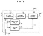
- Fig. 3 shows the structure of the input line interface 100A.
- the configuration includes a circuit 20 for extracting the VPI/VCI contained in the header field of an input cell received from the input line 1A, a header conversion table memory 21 which stores therein an output port identifier for each VCI/CPI such that when information of VCI/CPI is supplied from the extraction circuit 20 via a signal line 13, an output port identifier corresponding thereto is outputted from the table, and a header conversion circuit 22 for adding to the input cell the output identifier (routing information) delivered from the table 21.
- Fig. 3 further includes a policing unit 23 for implementing a policing method according to the present invention, which will be described later, and a cell discard control circuit 29 operative in response to a violation detection signal received from the policing unit 23 via a signal line 14 for marking or discarding wrong or violation cells excessively generated beyond the registered condition.
- a policing unit 23 for implementing a policing method according to the present invention, which will be described later
- a cell discard control circuit 29 operative in response to a violation detection signal received from the policing unit 23 via a signal line 14 for marking or discarding wrong or violation cells excessively generated beyond the registered condition.
- Fig. 4 shows an embodiment of the policing method achieved by the policing unit 2 according to the present invention.
- the abscissa stands for time and p1 to p8 denote arrival points of cells belonging to a call.
- two counter means A and B for respectively achieving count operations of the cells arrived at the system during the respective count periods of time T. These count periods of the counter means A and B are shifted in phase from each other by a period of time T/2.
- Fig. 5 shows an example of the structure of the policing unit 23 realizing the policing method described above.
- the unit 23 according to the present invention includes a plurality of traffic monitor blocks 23-1 to 23-j disposed in association with the VPIs and/or VCIs and a timer 26.
- Reference numeral 31 denotes a decoder for receiving a value outputted from the VPI/VCI extraction circuit 20 to indicate a virtual identifier VPI and/or a virtual channel identifier VCI of an input cell and selectively supplying an associated one of the count pulses 310-1 to 310-j to a traffic monitor block 23-i corresponding to the received value.
- a numeral 32 designates a decoder for receiving control parameters (the count period T and the threshold value X) supplied from the control processor 140 in a call setting operation via a signal line (or a bus) and distributing the parameters to a traffic monitor block 230i specified by the VPI/VCI.
- a reference numeral 33 indicates an OR circuit for ORing the decision signals from the respective traffic monitor blocks 23-1 to 23-N to supply the resultant value as a decision output of the policing unit 23 to the cell discard control circuit 29.
- the timer 26 measures elapse of time and is reset (to an initial value) at a fixed interval of time.
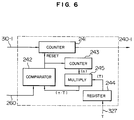
- the counter unit 24-1 includes, as shown in Fig. 6 by way of example, a first counter 241 for counting the count pulse 310-1, a comparator 242 for resetting the first counter 241, a second counter 243 for counting a reset pulse outputted from the comparator 242, a register 244 for storing therein a value T denoting a count period of time supplied from the decoder 32, and a multiplier 245 for producing a product T ⁇ n between the value T set in the decoder 32 and the count value n of the second counter 243.
- the comparator 242 compares the value t of the current time supplied from a timer 26 via a signal line 260 with the value T ⁇ n outputted from the multiplier 245. When t ⁇ T ⁇ n results, a reset pulse (RESET) is outputted. In consequence, thanks to the resetting operation of the counter value of the first counter 241 by the reset pulse (RESET), the number of cells arrived at the system in the time frames 61A, 62A, 63A, etc. of Fig. 4 each having the period of time T can be counted for each of the frame by the first counter 24.
- REET reset pulse
- the count values of input cells respectively obtained by the counters 24-1 and 24-N are respectively inputted to the comparators 25-1 and 25-N to be compared with the threshold value X. If "true” is developed as a result of the comparison in either one of the comparators, namely, if either one of the input cell count values exceeds the threshold value X, a signal 14-1 is sent to the control circuit 29 to discard the input ATM cell at the point of time.
- a traffic monitor for each call, there are arranged a plurality of counters respectively having count periods of time with a phase difference therebetween.
- the system includes a plurality of comparators for comparing the count values of the respective counters with the threshold X.
- the resultant outputs from the comparators is ORed to produce a logical sum thereof.
- the value of the count period T may vary between the calls.
- the number of input cells is counted by the plural counter units 24-1 to 24-N such that the respective count values are compared with the threshold value X by the comparators 25-1 to 25-N, respectively.
- the circuit may be configured such that the counter areas for the respective VPIs and/or VCIs are allocated in a memory. Namely, each time a cell is inputted, "one" is added to the value of count data in the pertinent memory area.
- the VPI/VCI is extracted from the header of the input cell by the circuit 20.
- the system may be structured such that a copy of the input cell is supplied to the decoder 31 so that the decoder 31 analyzes the header to generate the pulses 321-1 to 321-j.
- the copy of the input cell may be sent to the selected traffic monitor block 23-i to be counted by the counter unit.
- the configuration may be appropriately modified, for example, as above.
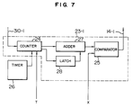
- Fig. 7 shows the construction of the policing unit 23-1 in a simplified form in another embodiment according to the present invention.
- a counter unit 24 is responsive, like the counter unit 24-1 shown in Fig. 5, to a setting value of a period T of time supplied from the control processor 140 to count the number of input cells for each predetermined period of time.
- the unit 24 measures the number of input cells during a period T/2 of time by an internal counter. The count of the internal counter is incremented each time a cell is inputted to the system and the count value obtained therefrom is fed to an adder circuit 27.
- the internal counter is reset (in an interval of of time T/2), the value thereof is fed to a latch circuit 28.
- the adder 27 adds the count value of input cells counted in a period T/2 by the counter 24 to that of input cells in a period T/2 immediately before the operation is achieved by the latch 28, thereby obtaining the number of input cells in the latest period T.
- the result of addition is compared with the threshold value X by a comparator 25. If the count value of the input cells is larger than the threshold value, a cell discard indication signal 14-1 is outputted from the comparator 25.
- burst cells such as the cells p2 to p7 of Fig. 4 can be advantageously detected by a simple constitution including a set of a counter unit and a comparator.
- Fig. 8 shows another embodiment of the policing method according to the present invention.
- the abscissa denotes time to present count periods of time and distribution of input cells along the lapse of time.
- each time frame is initiated at a timing synchronized with a cell input timing.
- a time frame 61A of counter means A is started to count the number of cells arriving at the system in this time frame.
- counter means initiates a time frame 61B corresponding to the time frame 61A at a timing delayed by a period of time T/2 relative to the start of each time frame (the arrival point of time of the cell p1 in this example) of the counter means A, thereby counting the number of input cells in the time frame 61B.
- the count value of input cells exceeds the associated threshold value in either one of the time frames, a signal is created to indicate discard of the input cell.
- N counter means N ⁇ 3
- the starting point of time frame need only be sequentially shifted by T/N for each counter means.
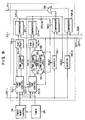
- Fig. 9 shows an embodiment of the policing unit according to the present invention for implementing the policing method of Fig. 8.
- This diagram shows one of the plural traffic monitor blocks arranged in association with the calls, namely, a traffic monitor block 53-i.
- counters 55-1 to 55-N are reset respectively by comparators 57-1 to 57-N at mutually different timings.
- Each counter counts the number of input cells (count pulses 310-i) received in the period T associated therewith.
- Reference numerals 58-1 to 58-N denote comparators for comparing the count values respectively of the counters 55-1 to 55-N with the threshold value X.
- Each comparator produces a cell discard signal when the count value exceeds the threshold value X.
- Numeral 59 stands for an OR circuit for generating a logical sum of the outputs from the comparators 58-1 to 58-N.
- the counters 55-1 to 55-N are reset by the following circuit constitution employing a time stamp.
- reference numerals 52-1 to 52-N designates start time control circuits for controlling initiation timings of the time frames, respectively.
- the circuit 52-1 After a reset signal 570-1 is received from the comparator 57-1, when a first cell is received, the circuit 52-1 sets as a reference time a value of the point of time indicated by the timer 26 to a time stamp latch circuit 54-1 and sends a timing signal 520 to the circuit 52-N. Thereafter, until the next reset signal is received from the comparator 57-1, the circuit 52-1 successively supplies a subtractor circuit 56-1 with the value of (current) time received from the timer 26.
- the circuit 56-1 computes a difference between the reference time set to the circuit 54-1 and the current time fed from the control circuit 52-1 to deliver the difference of time to the comparator 57-1.
- the comparator 57-1 compares the output value from the subtractor 56-1 with the value T set as the parameter of the count period. When the output value exceeds the value T, namely, when a period of time T is elapsed from the reference time, a reset signal 570-1 is sent to the counter 55-1 and the control circuit 52-1.
- the circuit 52-1 stops supplying the current time to the subtractor 56-1 and then repeatedly conducts outputting the reference time, the timing signal, and the current time when a first cell is received. Resultantly, the counter 55-1 counts the number of input cells in the time frames 61A, 62A, etc. of Fig. 8.
- control circuit 52-N loaded with the value T of the count period setting parameter supplied via a signal line 327' sets as a reference time, when the period of time T/2 is elapsed after a timing signal 520 is received from the circuit 52-1, a value of time indicated by the timer 26 to a time stamp latch circuit 54-N or 54-N'. Thereafter, the current time received from the timer 26 is sequentially supplied to a subtractor circuit 56-N.
- the subtractor 56-N produces a difference of time between the reference time stored in the latch 54-N or 54-N' selected by a selector 59' and each value of current time sequentially outputted from the control circuit 52-N to supply the difference of time to the comparator 57-N. If the difference exceeds the setting value T, a reset signal 570-N is produced by the comparator 57-N to be sent to the counter 55-N and the control circuit 52-N.
- the counter 55-N counts the number of input cells in the time frames 61B, 62B, and so forth of Fig. 8.
- the input cells are discarded by the discard control circuit 29.
- the values of start time respectively of the time frames 61B, 62B, etc. of the counter 55-N are delayed by T/2 respectively from those of the time frames 61A, 62A, etc. of the counter 55-1.
- the selectors 59 and 59' controlled by the reset signal 570-1 from the comparator 570-1 are adopted to select the time stamp latch circuit 54-N or 54-N'.
- the selectors 59 and 59' controlled by the reset signal 570-1 from the comparator 570-1 are adopted to select the time stamp latch circuit 54-N or 54-N'.
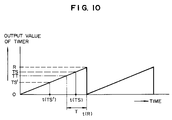
- Fig. 10 is a graph showing output signals from the timer 26.
- a timer is configured to count a finite or limited period of time. Namely, as shown by a saw-tooth waveform in Fig. 10, the timer output value is associated with a discontinuity. Specifically, in the count operation of time, when the output from the timer reaches a maximum value R, the output is returned to an initial value. Assume that a period of time in which the output from the timer is changed from the initial value to the maximum value (namely, a timer reset time) is sufficiently greater than the period of time T of each time frame.
- the output from the subtractor circuit has continuity. If the point of time to set the reference time is within one time frame of the reset time t(R) like in the case of the point t(TS), the output from the subtractor circuit is attended with discontinuity and hence there cannot be attained an appropriate decision result.
- a reference numeral 34 denotes a timer reset control circuit to obtain an appropriate result of the comparison achieved by each of the subtractors 56-1 to 56-N between the reference time and the current time in the domain of discontinuity of timer output value.
- the control circuit 34 achieves a control operation as follows.
- the reference time TS and the time stamp values take corrected values, for example, -(R - TS) .
Landscapes
- Engineering & Computer Science (AREA)
- Computer Networks & Wireless Communication (AREA)
- Signal Processing (AREA)
- Data Exchanges In Wide-Area Networks (AREA)
Applications Claiming Priority (2)
| Application Number | Priority Date | Filing Date | Title |
|---|---|---|---|
| JP2097492A JPH05219093A (ja) | 1992-02-06 | 1992-02-06 | ポリシング方法および回路 |
| JP20974/92 | 1992-02-06 |
Publications (2)
| Publication Number | Publication Date |
|---|---|
| EP0554859A2 true EP0554859A2 (fr) | 1993-08-11 |
| EP0554859A3 EP0554859A3 (fr) | 1994-10-12 |
Family
ID=12042140
Family Applications (1)
| Application Number | Title | Priority Date | Filing Date |
|---|---|---|---|
| EP19930101670 Withdrawn EP0554859A3 (fr) | 1992-02-06 | 1993-02-03 | Procédé et dispositif pour policer de cellules à ATM. |
Country Status (4)
| Country | Link |
|---|---|
| US (1) | US5828654A (fr) |
| EP (1) | EP0554859A3 (fr) |
| JP (1) | JPH05219093A (fr) |
| CA (1) | CA2088799C (fr) |
Cited By (2)
| Publication number | Priority date | Publication date | Assignee | Title |
|---|---|---|---|---|
| EP0981224A4 (fr) * | 1998-03-06 | 2001-06-06 | Nippon Telegraph & Telephone | Procede et appareil de commande de trafic |
| EP0851635A3 (fr) * | 1996-12-25 | 2001-09-05 | Hitachi, Ltd. | Commutateur IP, circuit interface et commutateur ATM pour le commutateur IP, ainsi qu'un système de réseau de commutation IP |
Families Citing this family (14)
| Publication number | Priority date | Publication date | Assignee | Title |
|---|---|---|---|---|
| JP3291875B2 (ja) * | 1993-12-06 | 2002-06-17 | 株式会社日立製作所 | ポリシング回路 |
| AU1205900A (en) * | 1998-10-27 | 2000-05-15 | Fujitsu Network Communications, Inc. | Network to network priority frame dequeuing |
| US6442140B1 (en) * | 1999-01-04 | 2002-08-27 | 3Com Corporation | Method for automatic setup of missing RM cell count parameter CRM in an ATM traffic management descriptor |
| KR20010108575A (ko) * | 2000-05-29 | 2001-12-08 | 은종명 | 초고속 폴리싱 장치 및 그 방법 |
| US7103039B1 (en) | 2001-03-16 | 2006-09-05 | Cisco Technology, Inc. | Hardware load balancing through multiple fabrics |
| US7184403B1 (en) | 2001-03-16 | 2007-02-27 | Cisco Technology, Inc. | Hardware load balancing through a single fabric |
| US7042848B2 (en) * | 2001-05-04 | 2006-05-09 | Slt Logic Llc | System and method for hierarchical policing of flows and subflows of a data stream |
| US6904057B2 (en) * | 2001-05-04 | 2005-06-07 | Slt Logic Llc | Method and apparatus for providing multi-protocol, multi-stage, real-time frame classification |
| US6901052B2 (en) * | 2001-05-04 | 2005-05-31 | Slt Logic Llc | System and method for policing multiple data flows and multi-protocol data flows |
| US6944168B2 (en) * | 2001-05-04 | 2005-09-13 | Slt Logic Llc | System and method for providing transformation of multi-protocol packets in a data stream |
| US7161904B2 (en) * | 2002-06-04 | 2007-01-09 | Fortinet, Inc. | System and method for hierarchical metering in a virtual router based network switch |
| US7499398B2 (en) * | 2003-04-16 | 2009-03-03 | International Business Machines Corporation | Method and system for oversubscribing bandwidth in a communications network |
| US20050214389A1 (en) * | 2004-03-26 | 2005-09-29 | Council Of Scientific And Industrial Research | Beta-carotene enriched extract from water hyacinth eichhornia crassipes |
| US20070002745A1 (en) * | 2005-07-01 | 2007-01-04 | Pmc-Sierra Israel Ltd. | Discard-sniffing device and method |
Family Cites Families (8)
| Publication number | Priority date | Publication date | Assignee | Title |
|---|---|---|---|---|
| FR2616025B1 (fr) * | 1987-05-26 | 1989-07-21 | Lespagnol Albert | Methode et systeme de controle de flux de paquets |
| NL8900269A (nl) * | 1989-02-03 | 1990-09-03 | Nederland Ptt | Methode voor het via een meervoud van asynchroon tijdverdeelde transmissiekanalen overdragen van een stroom van datacellen, waarbij per transmissiekanaal een tellerstand wordt bijgehouden, die afhankelijk is van het aantal datacellen per tijd. |
| JPH02220531A (ja) * | 1989-02-22 | 1990-09-03 | Toshiba Corp | 呼接続制御方式および流量監視方式 |
| US5050162A (en) * | 1989-03-20 | 1991-09-17 | Bell Communications Research, Inc. | Congestion free packet network |
| JPH04100342A (ja) * | 1990-08-20 | 1992-04-02 | Toshiba Corp | トラヒック制御方式 |
| US5200952A (en) * | 1991-03-28 | 1993-04-06 | Sprint International Communications Corp. | Adaptive VCP control in integrated services networks |
| US5164938A (en) * | 1991-03-28 | 1992-11-17 | Sprint International Communications Corp. | Bandwidth seizing in integrated services networks |
| US5179556A (en) * | 1991-08-02 | 1993-01-12 | Washington University | Bandwidth management and congestion control scheme for multicast ATM networks |
-
1992
- 1992-02-06 JP JP2097492A patent/JPH05219093A/ja active Pending
-
1993
- 1993-02-03 EP EP19930101670 patent/EP0554859A3/fr not_active Withdrawn
- 1993-02-04 CA CA002088799A patent/CA2088799C/fr not_active Expired - Fee Related
-
1996
- 1996-05-24 US US08/653,475 patent/US5828654A/en not_active Expired - Fee Related
Non-Patent Citations (3)
| Title |
|---|
| IEEE NETWORK: THE MAGAZINE OF COMPUTER COMMUNICATIONS, vol.4, no.3, May 1990, NEW YORK US G. GALLASSI 'Resource Management and Dimensioning in ATM Networks' * |
| INTERNATIONAL ZURICH SEMINAR ON DIGITAL COMMUNICATIONS, March 1990, NEW YORK US pages 131 - 144 DENISSEN F. ET AL. 'The Policing Function in an ATM Network' * |
| PHILIPS TELECOMMUNICATION REVIEW, vol.48, no.2, June 1990, HILVERSUM NL pages 24 - 32 J. VAN DER RHEE ET AL. 'ATM Traffic Capacity Modelling' * |
Cited By (4)
| Publication number | Priority date | Publication date | Assignee | Title |
|---|---|---|---|---|
| EP0851635A3 (fr) * | 1996-12-25 | 2001-09-05 | Hitachi, Ltd. | Commutateur IP, circuit interface et commutateur ATM pour le commutateur IP, ainsi qu'un système de réseau de commutation IP |
| US6526045B2 (en) | 1996-12-25 | 2003-02-25 | Hitachi, Ltd. | IP switch, interface circuit and ATM switch used for IP switch, and IP switch network system |
| US6993029B2 (en) | 1996-12-25 | 2006-01-31 | Hitachi, Ltd. | IP switch, interface circuit and ATM switch used for IP switch, and IP switch network system |
| EP0981224A4 (fr) * | 1998-03-06 | 2001-06-06 | Nippon Telegraph & Telephone | Procede et appareil de commande de trafic |
Also Published As
| Publication number | Publication date |
|---|---|
| JPH05219093A (ja) | 1993-08-27 |
| US5828654A (en) | 1998-10-27 |
| EP0554859A3 (fr) | 1994-10-12 |
| CA2088799A1 (fr) | 1993-08-07 |
| CA2088799C (fr) | 1998-08-25 |
Similar Documents
| Publication | Publication Date | Title |
|---|---|---|
| US5828654A (en) | ATM cell policing method and apparatus | |
| KR0161613B1 (ko) | Atm 인터페이스 및 섀핑 방법 | |
| EP0351818B1 (fr) | Système de commutation ATM | |
| US5295135A (en) | Arrangement for monitoring the bit rate in ATM networks | |
| US5513178A (en) | Cell multiplexing apparatus in ATM network | |
| US6295295B1 (en) | Scheduler for an information packet switch | |
| CA2043600C (fr) | Transmissions a debit binaire constant dans un commutateur de donnees a large bande | |
| KR960003783B1 (ko) | 광대역 종합정보통신망 가입자 액세스 장치의 비동기 전달방식(atm) 다중화 처리 장치 및 방법 | |
| US5373504A (en) | Apparatus and a method for setting a communication path | |
| US6687225B1 (en) | Bandwidth control apparatus | |
| EP0577269B1 (fr) | Dispositif pour restreindre le frétillement dans un système de commutation basé sur priorité | |
| EP0680235A1 (fr) | Generation d'identificateur de canal | |
| CA2076802A1 (fr) | Controleur de debit binaire pour reseaux mta | |
| JPH10145382A (ja) | Atm交換機のスイッチ制御回路 | |
| EP0788288A2 (fr) | ContrÔle de cours à un système de communication avec actionneur cellulaire | |
| GB2322258A (en) | Apparatus for scheduling cells based on pre-synchronized frames | |
| JP3505118B2 (ja) | トラフィックシェーパ | |
| US6504824B1 (en) | Apparatus and method for managing rate band | |
| EP0376597A2 (fr) | Sélection de paquets par des dispositifs de distributions de paquets | |
| US5862127A (en) | Method of controlling the peak cell rate spacing of multiplexed ATM traffic | |
| JP3079793B2 (ja) | 輻輳制御方法および呼受付制御方法 | |
| CA2233191A1 (fr) | Methode permettant de recevoir des cellules de message de connexions a faible priorite a partir d'un seul trajet de transmission redondant d'un groupe de trajets donne | |
| JP2852473B2 (ja) | セルトラヒック監視装置 | |
| KR100191257B1 (ko) | 비동기 전송모드 통신망에서의 가상시간 알고리듬을 이용한 실시간 큐 서비스장치 | |
| KR0128839B1 (ko) | 고속 패킷 스케줄링 제어장치 |
Legal Events
| Date | Code | Title | Description |
|---|---|---|---|
| PUAI | Public reference made under article 153(3) epc to a published international application that has entered the european phase |
Free format text: ORIGINAL CODE: 0009012 |
|
| AK | Designated contracting states |
Kind code of ref document: A2 Designated state(s): DE FR GB |
|
| PUAL | Search report despatched |
Free format text: ORIGINAL CODE: 0009013 |
|
| AK | Designated contracting states |
Kind code of ref document: A3 Designated state(s): DE FR GB |
|
| 17P | Request for examination filed |
Effective date: 19950213 |
|
| 17Q | First examination report despatched |
Effective date: 20010315 |
|
| STAA | Information on the status of an ep patent application or granted ep patent |
Free format text: STATUS: THE APPLICATION IS DEEMED TO BE WITHDRAWN |
|
| 18D | Application deemed to be withdrawn |
Effective date: 20010726 |