EP0555507A1 - Capteur de position - Google Patents
Capteur de position Download PDFInfo
- Publication number
- EP0555507A1 EP0555507A1 EP92102482A EP92102482A EP0555507A1 EP 0555507 A1 EP0555507 A1 EP 0555507A1 EP 92102482 A EP92102482 A EP 92102482A EP 92102482 A EP92102482 A EP 92102482A EP 0555507 A1 EP0555507 A1 EP 0555507A1
- Authority
- EP
- European Patent Office
- Prior art keywords
- tracks
- measuring device
- track
- graduation
- division
- Prior art date
- Legal status (The legal status is an assumption and is not a legal conclusion. Google has not performed a legal analysis and makes no representation as to the accuracy of the status listed.)
- Granted
Links
- 238000006073 displacement reaction Methods 0.000 claims description 10
- 238000012937 correction Methods 0.000 claims description 7
- 125000004122 cyclic group Chemical group 0.000 claims description 2
- 238000011156 evaluation Methods 0.000 description 4
- 238000005259 measurement Methods 0.000 description 4
- 238000001514 detection method Methods 0.000 description 2
- 238000000034 method Methods 0.000 description 2
- 230000015572 biosynthetic process Effects 0.000 description 1
- 230000008878 coupling Effects 0.000 description 1
- 238000010168 coupling process Methods 0.000 description 1
- 238000005859 coupling reaction Methods 0.000 description 1
- 230000001419 dependent effect Effects 0.000 description 1
- 230000009977 dual effect Effects 0.000 description 1
- 230000000694 effects Effects 0.000 description 1
- 230000001939 inductive effect Effects 0.000 description 1
- 230000005291 magnetic effect Effects 0.000 description 1
- 238000012423 maintenance Methods 0.000 description 1
- 230000003287 optical effect Effects 0.000 description 1
Images


Classifications
-
- G—PHYSICS
- G01—MEASURING; TESTING
- G01D—MEASURING NOT SPECIALLY ADAPTED FOR A SPECIFIC VARIABLE; ARRANGEMENTS FOR MEASURING TWO OR MORE VARIABLES NOT COVERED IN A SINGLE OTHER SUBCLASS; TARIFF METERING APPARATUS; MEASURING OR TESTING NOT OTHERWISE PROVIDED FOR
- G01D5/00—Mechanical means for transferring the output of a sensing member; Means for converting the output of a sensing member to another variable where the form or nature of the sensing member does not constrain the means for converting; Transducers not specially adapted for a specific variable
- G01D5/12—Mechanical means for transferring the output of a sensing member; Means for converting the output of a sensing member to another variable where the form or nature of the sensing member does not constrain the means for converting; Transducers not specially adapted for a specific variable using electric or magnetic means
- G01D5/244—Mechanical means for transferring the output of a sensing member; Means for converting the output of a sensing member to another variable where the form or nature of the sensing member does not constrain the means for converting; Transducers not specially adapted for a specific variable using electric or magnetic means influencing characteristics of pulses or pulse trains; generating pulses or pulse trains
- G01D5/24471—Error correction
- G01D5/24476—Signal processing
Definitions
- the invention relates to a displacement measuring device according to the preamble of claim 1.
- Such displacement measuring devices are known from a large number of publications. They are used to measure lengths or angles in machines and equipment.
- EP-B1-82 441 describes a method and devices for determining and correcting management errors. It contains, for example, additional measuring devices Scanning devices are arranged one behind the other in the measuring direction, changes in the distance between the scanning device and the material measure are recorded and offset in a correction computer with the coordinate values.
- the angular position of the scanning device relative to the division of the scale must be kept constant within very narrow limits over the entire measuring length in order to avoid measuring errors.
- the angular position of the scanning grating relative to the scale depends when the scanning device is on a special surface, e.g. a lateral scale surface is guided by the straightness of this tread.
- the object of the invention is to provide a displacement measuring device in which the guiding accuracy or the straightness does not have to be tolerated unnecessarily closely. This object is achieved by a displacement measuring device with the features of claim 1, advantageous configurations can be found in the Subclaims.
- the advantages of the displacement measuring device according to the invention are that the angular position of the scanning grating relative to the graduation marks on the scale can be measured at each scale point and a corresponding correction of the determined measured value can be carried out in the event of deviations from the desired angle.
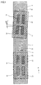
- a length measuring device 1 or the components relevant here is namely a material measure 11 and a scanning device 21 are shown.
- the material measure 11 has a graduation track 31, the individual grating lines of which run in a known manner transverse to the measuring direction X.
- the scanning device 21 is guided parallel to the material measure 11 in a manner not shown in detail.
- the scanning device 21 has scanning fields 41, 51, 61, 71 which have divisions which correspond to the division of the graduation track 31 and which are aligned at a predetermined angle ⁇ therewith. This angle ⁇ can be 0 ° or it can deviate from it.
- the angle ⁇ once set should ideally be constant over the entire measuring length.
- the ideal position is shown in the left part of Figure 1, the scanning device 21 is shown with dashed lines.
- the maintenance of the constant angle ⁇ between the scanning device 21 and the measuring standard 11 is directly dependent on the quality of the guidance of the scanning device 21 on the measuring standard 11. As soon as the guidance or its straightness is no longer subject to very narrow tolerances, tilting can occur between the measuring standard 11 and the scanning device 21, so that the angle ⁇ changes by the amount ⁇ ⁇ .
- the mentioned tilt angle ⁇ changes continuously depending on the straightness of the guide.
- the scanning fields 41, 61 and 51, 71 arranged at a transverse distance a enable the change in angle ⁇ ⁇ to be determined and thus ultimately a correction of the measured value as a function of the tilt angle.
- the determination of the angle change ⁇ Winkel according to the invention is of particular importance if the measuring standard has a code division with several division tracks. Such exemplary embodiments are shown in FIGS. 2 to 5 and are to be described in more detail below with reference to the previous basic explanations.
- FIG. 2 shows a material measure 12 with a graduation 32, which is formed from four graduation tracks 32a, 32b, 32c and 32d.
- This division 32 is constructed as a dual code.
- the invention can also be used successfully with any other code.
- the four graduation tracks 32a, 32b, 32c, 32d of the graduation 32 are scanned by a scanning device 22, which has four code division scanning fields 22a, 22b, 22c, 22d for this purpose, which in this example form a reading line that runs exactly perpendicular to the measuring direction ( dashed representation in the left part of the figure).
- the signals read by the code division scanning fields 22a, 22b, 22c, 22d are combined in an evaluation circuit to form the coded position value.
- the scanning device 22 is tilted due to guide errors, the angle ⁇ of the reading line changes.
- the signals obtained from the code division scanning fields 22a, 22b, 22c, 22d lead to an incorrect signal combination, which leads to an incorrect position value in the evaluation circuit.
- further scanning fields 42, 52, 62 and 72 are therefore provided, which supply analog signals from the graduation tracks 32a and 32d they have scanned. Analog signals are obtained from the individual tracks 32a and 32d, each of which corresponds to one scan of an incremental track with a corresponding grating constant.
- Two scanning fields 42, 62 and 52, 72 are provided per track in order, as already known and also shown in FIG. 1, to enable detection of the direction of movement.
- a tilted scanning device 22 is again shown, in which the angle ⁇ of the reading line is changed by the amount ⁇ ⁇ .
- the change in the angle ⁇ ⁇ can be determined by evaluating the analog signals generated by the scanning fields 42, 52 and 62, 72. If this change in angle ⁇ ⁇ is known, the incorrect position value can be corrected.
- the two outer graduation tracks 32a and 32d are used to determine the change in angle ⁇ selectedung.
- the evaluation of other graduation traces is also possible.
- the different division periods in the individual division traces must be taken into account in the evaluation.
- an interpolation can be carried out for the coarsest graduation track 32a which, provided there are no errors, leads to the same resolution as that of the finest graduation track 32d.
- This exemplary embodiment is particularly advantageous because, apart from the code division 32, no further division tracks are required in order to determine the change in angle ⁇ ⁇ and thus to be able to carry out the position value correction.
- a further graduation track 33I can be provided according to FIG. 3, which is designed as an incremental graduation and has the same resolution as the finest graduation track 33d the code division 33.
- the determination of the change in angle ⁇ ⁇ is then carried out analogously to the scanning of the two outer graduation tracks 33d and 33I as in the previous exemplary embodiments.
- the signals of the graduation tracks 33d and 33I can also be electronically interpolated.
- FIG. 4 Another variant is shown in FIG. 4.
- the code division 34 there are two separate incremental division tracks 34I and 34II, which preferably have the same division period.
- the determination of the angle change ⁇ ⁇ is carried out in the same way again with separate scanning fields 44, 54, 64 and 74, by means of whose scanning signals the angle changes ⁇ ⁇ are detected locally and for the correction of the code division scanning fields 24a, 24b, 24c, 24d read position can serve.
- the invention can be used in a particularly advantageous manner.
- a code division 35 with the division tracks 35a, 35b, 35c and 35d is shown schematically in FIG. You have incremental traces 35I, 35II of the same division period parallel. The tracks are read by a scanner 25.
Landscapes
- Engineering & Computer Science (AREA)
- Signal Processing (AREA)
- Physics & Mathematics (AREA)
- General Physics & Mathematics (AREA)
- Transmission And Conversion Of Sensor Element Output (AREA)
- Optical Transform (AREA)
Priority Applications (5)
| Application Number | Priority Date | Filing Date | Title |
|---|---|---|---|
| EP19920102482 EP0555507B1 (fr) | 1992-02-14 | 1992-02-14 | Capteur de position |
| DE59201199T DE59201199D1 (de) | 1992-02-14 | 1992-02-14 | Wegmesseinrichtung. |
| DE19934301971 DE4301971A1 (fr) | 1992-02-14 | 1993-01-26 | |
| DE9321274U DE9321274U1 (de) | 1992-02-14 | 1993-01-26 | Wegmeßeinrichtung |
| JP1282593A JP2649306B2 (ja) | 1992-02-14 | 1993-01-28 | 位置測定装置 |
Applications Claiming Priority (1)
| Application Number | Priority Date | Filing Date | Title |
|---|---|---|---|
| EP19920102482 EP0555507B1 (fr) | 1992-02-14 | 1992-02-14 | Capteur de position |
Publications (2)
| Publication Number | Publication Date |
|---|---|
| EP0555507A1 true EP0555507A1 (fr) | 1993-08-18 |
| EP0555507B1 EP0555507B1 (fr) | 1995-01-11 |
Family
ID=8209332
Family Applications (1)
| Application Number | Title | Priority Date | Filing Date |
|---|---|---|---|
| EP19920102482 Expired - Lifetime EP0555507B1 (fr) | 1992-02-14 | 1992-02-14 | Capteur de position |
Country Status (3)
| Country | Link |
|---|---|
| EP (1) | EP0555507B1 (fr) |
| JP (1) | JP2649306B2 (fr) |
| DE (2) | DE59201199D1 (fr) |
Cited By (6)
| Publication number | Priority date | Publication date | Assignee | Title |
|---|---|---|---|---|
| EP0836077A1 (fr) * | 1996-10-12 | 1998-04-15 | Dr. Johannes Heidenhain GmbH | Dispositif et procédé pour contrÔler les signaux dépendants de la position |
| GB2353595A (en) * | 1999-06-24 | 2001-02-28 | Mitutoyo Corp | Linear scale measuring device and position detection method |
| EP1271107A1 (fr) * | 2001-06-27 | 2003-01-02 | Dr. Johannes Heidenhain GmbH | Dispositif de mesure de position |
| US7359826B2 (en) | 2000-04-13 | 2008-04-15 | Dr. Johannes Heidenhain Gmbh | Method and device for detection of oscillations by a position measuring system |
| US7748251B2 (en) | 2006-06-28 | 2010-07-06 | Dr. Johannes Heidenhain Gmbh | Circuit configuration and method for ascertaining tilt errors in connection with a position-measuring device |
| EP2302331A3 (fr) * | 2009-09-18 | 2013-12-04 | Kabushiki Kaisha Yaskawa Denki | Codeur linéaire, système de moteur linéaire et procédé de fabrication du codeur linéaire |
Families Citing this family (21)
| Publication number | Priority date | Publication date | Assignee | Title |
|---|---|---|---|---|
| DE4328525A1 (de) * | 1993-08-25 | 1995-04-06 | Mikroelektronik Und Technologi | Längen- oder Winkelmeßeinrichtung |
| DE4420980C2 (de) * | 1994-06-16 | 1997-12-04 | Bosch Gmbh Robert | Elektrische Antriebsvorrichtung für Zugorgane, insbesondere für einen Gurt eines Rolladens |
| DE19523914C1 (de) * | 1995-06-30 | 1996-09-05 | Bosch Gmbh Robert | Vorrichtung zur Erfassung der Bewegung eines Antriebsgurts für einen Rolladenpanzer |
| DE19937162A1 (de) | 1999-08-06 | 2001-03-01 | Somfy Feinmech & Elektrotech | Elektrische Antriebsvorrichtung für einen Gurt, insbesondere einen Rolladengurt |
| DE50015787D1 (de) * | 1999-09-16 | 2009-12-24 | Heidenhain Gmbh Dr Johannes | Vorrichtung zur Positionsbestimmung und Ermittlung von Führungsfehlern |
| DE10247319B3 (de) * | 2002-10-10 | 2004-02-12 | Robert Bosch Gmbh | Verfahren zur Tiltiwinkelkompensation einer Sensoranordnung zur Erfassung einer Bewegung oder eines Drehwinkels |
| JP4783698B2 (ja) * | 2006-09-05 | 2011-09-28 | 株式会社ミツトヨ | 電磁誘導式エンコーダ |
| WO2010112082A1 (fr) * | 2009-04-03 | 2010-10-07 | Csem Centre Suisse D'electronique Et De Microtechnique Sa Recherche Et Developpement | Codeur de position unidimensionnel |
| JP2011257315A (ja) * | 2010-06-10 | 2011-12-22 | National Univ Corp Shizuoka Univ | 計測装置 |
| US8729892B2 (en) * | 2011-04-01 | 2014-05-20 | Allegro Microsystems, Llc | Differential magnetic field sensor structure for orientation independent measurement |
| DE102011079961A1 (de) * | 2011-07-28 | 2013-01-31 | Dr. Johannes Heidenhain Gmbh | Vorrichtung und Verfahren zur Winkelmessung |
| JP5968062B2 (ja) * | 2012-05-02 | 2016-08-10 | キヤノン株式会社 | 位置検出エンコーダおよびこれを用いた装置 |
| JP6134964B2 (ja) * | 2012-11-12 | 2017-05-31 | 株式会社ミツトヨ | 誘導型変位検出装置 |
| JP6114538B2 (ja) | 2012-12-04 | 2017-04-12 | 株式会社ミツトヨ | 光電式絶対位置検出器、及び、その取付方法 |
| JP6207154B2 (ja) * | 2012-12-28 | 2017-10-04 | キヤノン株式会社 | スケール、変位検出装置、レンズ装置、撮像システム、および、組み立て装置 |
| JP6422201B2 (ja) * | 2013-03-28 | 2018-11-14 | キヤノン株式会社 | 位置検出手段 |
| DE102016204016A1 (de) * | 2016-03-11 | 2017-09-14 | Robert Bosch Gmbh | Kipptoleranter Wegsensor |
| JP6893819B2 (ja) * | 2017-04-06 | 2021-06-23 | 株式会社ミツトヨ | エンコーダ |
| JP6879810B2 (ja) * | 2017-04-27 | 2021-06-02 | オークマ株式会社 | 光学式エンコーダ |
| GB201916662D0 (en) | 2019-11-15 | 2020-01-01 | Renishaw Plc | Encoder apparatus |
| GB201916641D0 (en) | 2019-11-15 | 2020-01-01 | Renishaw Plc | Position measurement device |
Citations (5)
| Publication number | Priority date | Publication date | Assignee | Title |
|---|---|---|---|---|
| US2866946A (en) * | 1955-09-26 | 1958-12-30 | Inductosyn Corp | Machine tool control |
| DE3412128C1 (de) * | 1984-03-31 | 1985-05-09 | Dr. Johannes Heidenhain Gmbh, 8225 Traunreut | Positionsmesseinrichtung |
| EP0325149A2 (fr) * | 1988-01-22 | 1989-07-26 | Dr. Johannes Heidenhain GmbH | Dispositif de mesure de la position |
| US4920259A (en) * | 1988-09-30 | 1990-04-24 | Hewlett-Packard Company | Apparatus for producing a phase insensitive index pulse for motion encoders |
| EP0412481A2 (fr) * | 1989-08-08 | 1991-02-13 | Dr. Johannes Heidenhain GmbH | Dispositif de mesure d'angles ou de longueurs |
-
1992
- 1992-02-14 DE DE59201199T patent/DE59201199D1/de not_active Expired - Fee Related
- 1992-02-14 EP EP19920102482 patent/EP0555507B1/fr not_active Expired - Lifetime
-
1993
- 1993-01-26 DE DE19934301971 patent/DE4301971A1/de not_active Withdrawn
- 1993-01-28 JP JP1282593A patent/JP2649306B2/ja not_active Expired - Fee Related
Patent Citations (5)
| Publication number | Priority date | Publication date | Assignee | Title |
|---|---|---|---|---|
| US2866946A (en) * | 1955-09-26 | 1958-12-30 | Inductosyn Corp | Machine tool control |
| DE3412128C1 (de) * | 1984-03-31 | 1985-05-09 | Dr. Johannes Heidenhain Gmbh, 8225 Traunreut | Positionsmesseinrichtung |
| EP0325149A2 (fr) * | 1988-01-22 | 1989-07-26 | Dr. Johannes Heidenhain GmbH | Dispositif de mesure de la position |
| US4920259A (en) * | 1988-09-30 | 1990-04-24 | Hewlett-Packard Company | Apparatus for producing a phase insensitive index pulse for motion encoders |
| EP0412481A2 (fr) * | 1989-08-08 | 1991-02-13 | Dr. Johannes Heidenhain GmbH | Dispositif de mesure d'angles ou de longueurs |
Cited By (12)
| Publication number | Priority date | Publication date | Assignee | Title |
|---|---|---|---|---|
| EP0836077A1 (fr) * | 1996-10-12 | 1998-04-15 | Dr. Johannes Heidenhain GmbH | Dispositif et procédé pour contrÔler les signaux dépendants de la position |
| US5883298A (en) * | 1996-10-12 | 1999-03-16 | Dr. Johannes Heidenhain Gmbh | Control device and process for testing position-dependent signals of a position measuring device |
| GB2353595A (en) * | 1999-06-24 | 2001-02-28 | Mitutoyo Corp | Linear scale measuring device and position detection method |
| US6521885B1 (en) | 1999-06-24 | 2003-02-18 | Mitutoyo Corporation | Linear scale measuring device and position detection method using the same |
| GB2353595B (en) * | 1999-06-24 | 2003-06-25 | Mitutoyo Corp | Linear scale measuring device and position detection method using the same |
| US6642509B2 (en) | 1999-06-24 | 2003-11-04 | Mitutoyo Corporation | Linear scale measuring device and position detection method using the same |
| DE10030479B4 (de) * | 1999-06-24 | 2004-01-29 | Mitutoyo Corp., Kawasaki | Linearmaßstabs-Messgerät und Positionserfassungsverfahren unter Anwendung desselben |
| US7359826B2 (en) | 2000-04-13 | 2008-04-15 | Dr. Johannes Heidenhain Gmbh | Method and device for detection of oscillations by a position measuring system |
| EP1271107A1 (fr) * | 2001-06-27 | 2003-01-02 | Dr. Johannes Heidenhain GmbH | Dispositif de mesure de position |
| US6914235B2 (en) | 2001-06-27 | 2005-07-05 | Dr. Johannes Heidenhain Gmbh | Position measuring system and method for operating a position measuring system |
| US7748251B2 (en) | 2006-06-28 | 2010-07-06 | Dr. Johannes Heidenhain Gmbh | Circuit configuration and method for ascertaining tilt errors in connection with a position-measuring device |
| EP2302331A3 (fr) * | 2009-09-18 | 2013-12-04 | Kabushiki Kaisha Yaskawa Denki | Codeur linéaire, système de moteur linéaire et procédé de fabrication du codeur linéaire |
Also Published As
| Publication number | Publication date |
|---|---|
| JP2649306B2 (ja) | 1997-09-03 |
| JPH07324948A (ja) | 1995-12-12 |
| DE4301971A1 (fr) | 1993-08-19 |
| EP0555507B1 (fr) | 1995-01-11 |
| DE59201199D1 (de) | 1995-02-23 |
Similar Documents
| Publication | Publication Date | Title |
|---|---|---|
| EP0555507B1 (fr) | Capteur de position | |
| DE69113415T2 (de) | Positionskodierer für Linear- oder Winkelmessapparat. | |
| DE3144334C2 (de) | Wegmeßeinrichtung mit Referenzmarken | |
| DE69205459T2 (de) | Kombinierter optischer und kapazitiver Apparat zur Messung der absoluten Position. | |
| EP0172323B1 (fr) | Appareil de mesure | |
| EP0628789B1 (fr) | Dispositif de mesure de position | |
| EP0085787B1 (fr) | Dispositif de mesure | |
| EP0268558B1 (fr) | Appareil pour la mesure de longueurs ou d'angles | |
| EP1923670B1 (fr) | Dispositif de mesure de position | |
| EP3724609B1 (fr) | Dispositif de mesure linéaire pour déterminer une position absolue et guidage linéaire avec un tel dispositif de mesure | |
| DE10041507A1 (de) | Lenkwinkelsensor für Kraftfahrzeuge | |
| EP1995566B1 (fr) | Echelle pour un dispositif de mesure de position et dispositif de mesure de position | |
| DE3542514C2 (fr) | ||
| DE69515273T2 (de) | Magnetischer Kodierer zum Lesen von Markierungen auf einer dazugehörigen magnetischen Spur | |
| DE3036830C2 (de) | Verfahren zur Korrektur von Meßwerten bei einem digitalen elektrischen Längen- oder Winkelmeßsystem | |
| EP1195579B1 (fr) | Procédé de détermination de la position absolue | |
| EP0895063B1 (fr) | Dispositif de mesure de position | |
| EP1748283A2 (fr) | Détecteur sensible au champ magnétique | |
| EP1321743B1 (fr) | Système pour mesurer une longueur absolue comprenant une barre de mesure qui se déplace relativement par rapport à des sondes de longueur mutuellement espacées | |
| DE10309679B4 (de) | Abtasteinheit zum Abtasten einer Maßverkörperung | |
| EP1006342B1 (fr) | Procédé de marquage des pistes de mesure | |
| DE69113920T2 (de) | Servosignalaufnahmemethode und Gerät dazu. | |
| EP2116814B1 (fr) | Dispositif de mesure destiné à la détermination d'une position et/ou d'une vitesse | |
| EP0526730B1 (fr) | Capteur de position linéaire ou angulaire | |
| DE4225320C1 (de) | Absolut-Längenmeßsystem zur Bestimmung der Lage zweier relativ zueinander beweglicher Objekte |
Legal Events
| Date | Code | Title | Description |
|---|---|---|---|
| PUAI | Public reference made under article 153(3) epc to a published international application that has entered the european phase |
Free format text: ORIGINAL CODE: 0009012 |
|
| 17P | Request for examination filed |
Effective date: 19920314 |
|
| AK | Designated contracting states |
Kind code of ref document: A1 Designated state(s): DE FR GB IT |
|
| 17Q | First examination report despatched |
Effective date: 19931203 |
|
| ITF | It: translation for a ep patent filed | ||
| GRAA | (expected) grant |
Free format text: ORIGINAL CODE: 0009210 |
|
| AK | Designated contracting states |
Kind code of ref document: B1 Designated state(s): DE FR GB IT |
|
| ET | Fr: translation filed | ||
| GBT | Gb: translation of ep patent filed (gb section 77(6)(a)/1977) |
Effective date: 19950120 |
|
| REF | Corresponds to: |
Ref document number: 59201199 Country of ref document: DE Date of ref document: 19950223 |
|
| PLBE | No opposition filed within time limit |
Free format text: ORIGINAL CODE: 0009261 |
|
| STAA | Information on the status of an ep patent application or granted ep patent |
Free format text: STATUS: NO OPPOSITION FILED WITHIN TIME LIMIT |
|
| 26N | No opposition filed | ||
| REG | Reference to a national code |
Ref country code: GB Ref legal event code: IF02 |
|
| PGFP | Annual fee paid to national office [announced via postgrant information from national office to epo] |
Ref country code: FR Payment date: 20050210 Year of fee payment: 14 |
|
| PGFP | Annual fee paid to national office [announced via postgrant information from national office to epo] |
Ref country code: IT Payment date: 20060228 Year of fee payment: 15 |
|
| REG | Reference to a national code |
Ref country code: FR Ref legal event code: ST Effective date: 20061031 |
|
| PG25 | Lapsed in a contracting state [announced via postgrant information from national office to epo] |
Ref country code: FR Free format text: LAPSE BECAUSE OF NON-PAYMENT OF DUE FEES Effective date: 20060228 |
|
| PGFP | Annual fee paid to national office [announced via postgrant information from national office to epo] |
Ref country code: GB Payment date: 20080220 Year of fee payment: 17 Ref country code: DE Payment date: 20080219 Year of fee payment: 17 |
|
| PG25 | Lapsed in a contracting state [announced via postgrant information from national office to epo] |
Ref country code: IT Free format text: LAPSE BECAUSE OF NON-PAYMENT OF DUE FEES Effective date: 20070214 |
|
| GBPC | Gb: european patent ceased through non-payment of renewal fee |
Effective date: 20090214 |
|
| PG25 | Lapsed in a contracting state [announced via postgrant information from national office to epo] |
Ref country code: DE Free format text: LAPSE BECAUSE OF NON-PAYMENT OF DUE FEES Effective date: 20090901 |
|
| PG25 | Lapsed in a contracting state [announced via postgrant information from national office to epo] |
Ref country code: GB Free format text: LAPSE BECAUSE OF NON-PAYMENT OF DUE FEES Effective date: 20090214 |