EP0555746A1 - Dispositif pour la réduction catalytique de NOx - Google Patents
Dispositif pour la réduction catalytique de NOx Download PDFInfo
- Publication number
- EP0555746A1 EP0555746A1 EP93101624A EP93101624A EP0555746A1 EP 0555746 A1 EP0555746 A1 EP 0555746A1 EP 93101624 A EP93101624 A EP 93101624A EP 93101624 A EP93101624 A EP 93101624A EP 0555746 A1 EP0555746 A1 EP 0555746A1
- Authority
- EP
- European Patent Office
- Prior art keywords
- evaporator
- urea
- urea solution
- catalytic converter
- exhaust gas
- Prior art date
- Legal status (The legal status is an assumption and is not a legal conclusion. Google has not performed a legal analysis and makes no representation as to the accuracy of the status listed.)
- Granted
Links
Images


Classifications
-
- F—MECHANICAL ENGINEERING; LIGHTING; HEATING; WEAPONS; BLASTING
- F01—MACHINES OR ENGINES IN GENERAL; ENGINE PLANTS IN GENERAL; STEAM ENGINES
- F01N—GAS-FLOW SILENCERS OR EXHAUST APPARATUS FOR MACHINES OR ENGINES IN GENERAL; GAS-FLOW SILENCERS OR EXHAUST APPARATUS FOR INTERNAL-COMBUSTION ENGINES
- F01N3/00—Exhaust or silencing apparatus having means for purifying, rendering innocuous, or otherwise treating exhaust
- F01N3/08—Exhaust or silencing apparatus having means for purifying, rendering innocuous, or otherwise treating exhaust for rendering innocuous
- F01N3/10—Exhaust or silencing apparatus having means for purifying, rendering innocuous, or otherwise treating exhaust for rendering innocuous by thermal or catalytic conversion of noxious components of exhaust
- F01N3/18—Exhaust or silencing apparatus having means for purifying, rendering innocuous, or otherwise treating exhaust for rendering innocuous by thermal or catalytic conversion of noxious components of exhaust characterised by methods of operation; Control
- F01N3/20—Exhaust or silencing apparatus having means for purifying, rendering innocuous, or otherwise treating exhaust for rendering innocuous by thermal or catalytic conversion of noxious components of exhaust characterised by methods of operation; Control specially adapted for catalytic conversion
- F01N3/206—Adding periodically or continuously substances to exhaust gases for promoting purification, e.g. catalytic material in liquid form, NOx reducing agents
- F01N3/2066—Selective catalytic reduction [SCR]
-
- B—PERFORMING OPERATIONS; TRANSPORTING
- B01—PHYSICAL OR CHEMICAL PROCESSES OR APPARATUS IN GENERAL
- B01D—SEPARATION
- B01D53/00—Separation of gases or vapours; Recovering vapours of volatile solvents from gases; Chemical or biological purification of waste gases, e.g. engine exhaust gases, smoke, fumes, flue gases, aerosols
- B01D53/34—Chemical or biological purification of waste gases
- B01D53/92—Chemical or biological purification of waste gases of engine exhaust gases
- B01D53/94—Chemical or biological purification of waste gases of engine exhaust gases by catalytic processes
- B01D53/9404—Removing only nitrogen compounds
- B01D53/9409—Nitrogen oxides
-
- B—PERFORMING OPERATIONS; TRANSPORTING
- B01—PHYSICAL OR CHEMICAL PROCESSES OR APPARATUS IN GENERAL
- B01D—SEPARATION
- B01D53/00—Separation of gases or vapours; Recovering vapours of volatile solvents from gases; Chemical or biological purification of waste gases, e.g. engine exhaust gases, smoke, fumes, flue gases, aerosols
- B01D53/34—Chemical or biological purification of waste gases
- B01D53/92—Chemical or biological purification of waste gases of engine exhaust gases
- B01D53/94—Chemical or biological purification of waste gases of engine exhaust gases by catalytic processes
- B01D53/9404—Removing only nitrogen compounds
- B01D53/9409—Nitrogen oxides
- B01D53/9431—Processes characterised by a specific device
-
- B—PERFORMING OPERATIONS; TRANSPORTING
- B01—PHYSICAL OR CHEMICAL PROCESSES OR APPARATUS IN GENERAL
- B01D—SEPARATION
- B01D53/00—Separation of gases or vapours; Recovering vapours of volatile solvents from gases; Chemical or biological purification of waste gases, e.g. engine exhaust gases, smoke, fumes, flue gases, aerosols
- B01D53/34—Chemical or biological purification of waste gases
- B01D53/92—Chemical or biological purification of waste gases of engine exhaust gases
- B01D53/94—Chemical or biological purification of waste gases of engine exhaust gases by catalytic processes
- B01D53/9495—Controlling the catalytic process
-
- F—MECHANICAL ENGINEERING; LIGHTING; HEATING; WEAPONS; BLASTING
- F01—MACHINES OR ENGINES IN GENERAL; ENGINE PLANTS IN GENERAL; STEAM ENGINES
- F01N—GAS-FLOW SILENCERS OR EXHAUST APPARATUS FOR MACHINES OR ENGINES IN GENERAL; GAS-FLOW SILENCERS OR EXHAUST APPARATUS FOR INTERNAL-COMBUSTION ENGINES
- F01N2240/00—Combination or association of two or more different exhaust treating devices, or of at least one such device with an auxiliary device, not covered by indexing codes F01N2230/00 or F01N2250/00, one of the devices being
- F01N2240/20—Combination or association of two or more different exhaust treating devices, or of at least one such device with an auxiliary device, not covered by indexing codes F01N2230/00 or F01N2250/00, one of the devices being a flow director or deflector
-
- F—MECHANICAL ENGINEERING; LIGHTING; HEATING; WEAPONS; BLASTING
- F01—MACHINES OR ENGINES IN GENERAL; ENGINE PLANTS IN GENERAL; STEAM ENGINES
- F01N—GAS-FLOW SILENCERS OR EXHAUST APPARATUS FOR MACHINES OR ENGINES IN GENERAL; GAS-FLOW SILENCERS OR EXHAUST APPARATUS FOR INTERNAL-COMBUSTION ENGINES
- F01N2240/00—Combination or association of two or more different exhaust treating devices, or of at least one such device with an auxiliary device, not covered by indexing codes F01N2230/00 or F01N2250/00, one of the devices being
- F01N2240/40—Combination or association of two or more different exhaust treating devices, or of at least one such device with an auxiliary device, not covered by indexing codes F01N2230/00 or F01N2250/00, one of the devices being a hydrolysis catalyst
-
- F—MECHANICAL ENGINEERING; LIGHTING; HEATING; WEAPONS; BLASTING
- F01—MACHINES OR ENGINES IN GENERAL; ENGINE PLANTS IN GENERAL; STEAM ENGINES
- F01N—GAS-FLOW SILENCERS OR EXHAUST APPARATUS FOR MACHINES OR ENGINES IN GENERAL; GAS-FLOW SILENCERS OR EXHAUST APPARATUS FOR INTERNAL-COMBUSTION ENGINES
- F01N2610/00—Adding substances to exhaust gases
- F01N2610/02—Adding substances to exhaust gases the substance being ammonia or urea
-
- F—MECHANICAL ENGINEERING; LIGHTING; HEATING; WEAPONS; BLASTING
- F01—MACHINES OR ENGINES IN GENERAL; ENGINE PLANTS IN GENERAL; STEAM ENGINES
- F01N—GAS-FLOW SILENCERS OR EXHAUST APPARATUS FOR MACHINES OR ENGINES IN GENERAL; GAS-FLOW SILENCERS OR EXHAUST APPARATUS FOR INTERNAL-COMBUSTION ENGINES
- F01N2610/00—Adding substances to exhaust gases
- F01N2610/08—Adding substances to exhaust gases with prior mixing of the substances with a gas, e.g. air
-
- Y—GENERAL TAGGING OF NEW TECHNOLOGICAL DEVELOPMENTS; GENERAL TAGGING OF CROSS-SECTIONAL TECHNOLOGIES SPANNING OVER SEVERAL SECTIONS OF THE IPC; TECHNICAL SUBJECTS COVERED BY FORMER USPC CROSS-REFERENCE ART COLLECTIONS [XRACs] AND DIGESTS
- Y02—TECHNOLOGIES OR APPLICATIONS FOR MITIGATION OR ADAPTATION AGAINST CLIMATE CHANGE
- Y02T—CLIMATE CHANGE MITIGATION TECHNOLOGIES RELATED TO TRANSPORTATION
- Y02T10/00—Road transport of goods or passengers
- Y02T10/10—Internal combustion engine [ICE] based vehicles
- Y02T10/12—Improving ICE efficiencies
Definitions
- the invention relates to a device for catalytic NO x reduction in oxygen-containing exhaust gases using urea, with a reduction catalyst contained in an exhaust pipe and a urea container which is connected to the exhaust gas flow by means of a feed device, the feed device having a spray can with which liquid Urea solution can be sprayed on an evaporator.
- urea as a reducing agent for the selective catalytic reduction (SCR) of nitrogen oxides in oxygen-containing exhaust gases is known (see, for example, DE-OS 38 30 045, Held et al, SAE paper 900 496 (1990), pages 13 to 19).
- the urea avoids the use of the toxic and intensely smelling ammonia and thus the transport of ammonia in motor vehicles and the storage of ammonia, which require appropriate safety precautions.
- the urea solution is sprayed directly into the exhaust pipe upstream of the reduction catalytic converter (SCR catalytic converter). With this procedure, undesired reaction products are formed.
- SCR catalytic converter reduction catalytic converter
- the urea decomposes with evolution of gas (NH3, CO2) to the infusible cyanuric acid (Cns) when it is heated above the melting point (133 ° C).
- NH3, CO2 infusible cyanuric acid
- HNCO reactive isocyanic acid
- Biuret, Cns and Ammelid remain in the residue. The formation of Cns, Ammelid and other substances is very difficult for gasification of the urea, since the solid urea initially produces liquid urea, but then again solid, infusible substances.
- the invention has for its object to further develop the device according to DE 40 38 054 in such a way that a reduction in the space required by the exhaust gas aftertreatment device, consisting of evaporator, hydrolysis and SCR catalyst, which is necessary for vehicle installation, is achieved, with the quantitative decomposition of the urea NH3 and CO2 is to be ensured.
- the invention is based on the knowledge that the efficiency of the urea decomposition is stored by using evaporator or hydrolysis inserts with non-linear channels over an efficiency of 99.9% and thus the occurrence of the side effects listed above can be avoided.
- the evaporator is equipped with thin, non-linear channels which are in fluid communication with one another via slots or small openings.
- the urea solution mist coming from the nozzle is divided into a large number of flow threads, which are deflected within the evaporator, partially brought together and separated again. This ensures that the solution droplets come into contact with the heat-transferring wall of the channels as quickly as possible.
- partial cross-flows are also possible due to pressure differences within caused by adjacent channels.
- the cross flows ensure an even distribution of the solution or steam flow over the entire cross section of the evaporator and the subsequent SCR catalytic converter.
- This distribution can be supported by dividing the evaporator in the main flow direction into two or more parts if these are connected in series with an intermediate gap in each case.
- the intermediate gap can produce a more intensive vertical flow component if the evaporator is occupied to different extents over the cross section.
- the above-described design of the evaporator successfully prevents droplets of the urea solution from slipping through the evaporator without coming into contact with the channel wall and thus not being evaporated.
- the evaporator is preferably made of metal with high thermal conductivity, the channels being separated from one another by very thin metal walls which have slots or bores for the transverse flows.
- the metal walls allow a rapid supply of heat to the point of impact of a solution droplet and thus to the evaporation of the droplets. Cold spots, as they occur with ceramics, are avoided.
- Such an evaporator can preferably be produced from a correspondingly profiled, thin metal foil which also has slots or bores.
- the film is then rolled up in a spiral (single or multi-course in the case of larger diameters) to form the evaporator and surrounded by a cylindrical jacket.
- the profiles are designed in such a way that, after being rolled up, they essentially form axially directed channels, which, however, do not run in a straight line, but instead have deflections which occur at short intervals, approximately every 5-10 mm.
- the channels and the slots or bores preferably have diameters in the range of a few millimeters, in particular between 1/2 and 2 mm.
- the channel walls of the evaporator are coated with an absorbent material which is preferably open-pore in order to enlarge the surface.
- an absorbent material which is preferably open-pore in order to enlarge the surface.
- inorganic oxides In order to accelerate the evaporation / hydrolysis sufficiently and to inhibit the formation of undesired by-products, all components that come into contact with urea-water mist, in particular the catalyst support structure, are coated with finely divided inorganic oxides.
- the inorganic oxides must be resistant to the exhaust gas of diesel engines at temperatures up to 700 ° C and their pore structure must remain stable over several thousand hours of operation. Mixtures of aluminum oxide with titanium dioxide, silicon dioxide, zirconium dioxide and / or H-zeolites in the weight ratio between aluminum oxide and the other oxides of 90:10 to 10:90 are therefore used.
- H-zeolite-containing metal oxide mixtures gives the hydrolysis catalyst an additional activity for the selective catalytic reduction of NO x with NH3 and therefore allows the volume of the SCR catalyst to be reduced by 10 to 30%.
- H-mordenite, H-ZSM5 and dealuminated, Si-rich cracking catalysts have proven themselves as diesel exhaust gas-resistant H-zeolites.
- finely divided metal oxides mentioned in the patent claim are particularly effective, however, the following carriers can be added alone or in a mixture: Nb2O5, Ta2O5, WO3, aluminum silicate and other zeolites, such as dealuminated cracking catalysts.
- the evaporator or hydrolysis catalytic converter is preferably arranged in the exhaust pipe, where it is fixed upstream of the reduction catalytic converter. This has the advantage that the heat for evaporation and hydrolysis is used directly from the exhaust gas stream.
- the exhaust gas which also flows through the evaporator, transports the urea mist.
- the evaporator preferably occupies the entire cross section of the exhaust pipe. However, it is also possible to make the evaporator smaller in order to allow a partial flow of the exhaust gases to flow around it and thus achieve a homogenization of the temperature.
- an oxidation catalytic converter can also be provided downstream of the reduction catalytic converter.
- the evaporator and the catalysts can be combined in a housing in which at least one sound absorption damper is also integrated.
- a sound absorption damper can be approximately funnel-shaped in accordance with a simple production engineering configuration and can be provided with passages through which, in the event of exhaust gas vibrations, gas into an absorption material, e.g. Mineral wool or steel wool, filled expansion room can enter. This damper is arranged after the catalytic converters in the exhaust gas flow direction. It is advantageous if the housing in the exhaust gas inlet area, ie. H. already has sound insulation before the exhaust gas and urea solution are mixed.
- baffles are provided on the inflow side to support the most uniform possible distribution of the urea solution mist over the cross section of the evaporator.
- the baffles can be designed, for example, so that they allow the exhaust gas flow to strike the urea solution stream in a vortex-like manner, so that there is a strong mixing and thus good distribution of the solution droplets on the evaporator before the evaporator.
- a pressure atomizer nozzle As a spray nozzle, a pressure atomizer nozzle is proposed, which is connected to a longer emulsifying line, in the other end of which a compressed air line and a supply line for the urea solution open out, ie. That is, the compressed air line opens into the urea feed line as close as possible to the solution reservoir. In this way, an extensive gas / solution mixture can be achieved before it exits through the nozzle, which supports the finest possible atomization of the solution.
- the emulsifying line which is filled with compressed air and urea solution, the uneven solution specifications caused by a metering device are evened out, so that a uniform solution flow is ensured at the pressure atomizing nozzle.
- a pressure container which can be connected to the same compressed air network, is preferably used as the storage container for the urea solution.
- the urea solution supply in connection with the pressure vessel can be precisely metered by means of a pulse width modulated solenoid valve.
- the use of a This makes a pump, which is susceptible to urea crystals and also not precisely controllable, unnecessary.
- the solenoid valve for metering the urea solution is regulated as a function of the load and the speed of the internal combustion engine emitting the exhaust gas.
- the need for urea solution can be adapted precisely to the operating situation and NO x concentration in the exhaust gas, so that an accumulation of ammonia converted from the urea solution in the reduction catalytic converter is avoided and thus a trouble-free operation of the reduction catalytic converter is ensured.
- metering can be proportional to the NO x mass flow in the exhaust gas.
- the urea solution is incompletely converted into ammonia and CO2 at low temperatures, below 160 ° C, with the formation of by-products. It is therefore proposed to superimpose a temperature control on the metering control, which completely prevents the supply of urea solution when the exhaust gas temperatures in the area of the catalysts fall below predetermined values.
- the spray nozzle and any guide plates are preferably integrated in the housing for the evaporator.
- the housing for the evaporator.
- at least the areas that come into contact with the urea solution are provided with a heat-conducting coating that catches drops of solution, so that the drops that come into contact with the walls are rapidly evaporated and hydrolysed bring.
- a reduction catalytic converter 5 (SCR catalytic converter) is interposed in the exhaust gas line 2.
- Ammonia which is obtained by reacting a urea solution 6, is used as the reducing agent.
- the urea solution 6 is located in a pressure vessel 7 and is converted into ammonia and CO2 within the exhaust pipe 2 using the heat from the exhaust gases 12 by evaporation and hydrolysis. Mixed with the exhaust gases 12 ′, these gases enter the SCR catalytic converter 5.
- an evaporator 3 and hydrolysis catalytic converter 4 are arranged in the exhaust pipe 2 in the flow direction of the exhaust gas 12 upstream of the SCR catalytic converter for the implementation of the urea solution 6.
- the evaporator 3 is constructed in two parts, the two evaporator parts 3a and 3b being arranged one behind the other while maintaining a gap 8.
- the evaporator parts 3a and 3b consist of heat-conducting sheet metal, which is shaped for the simultaneous formation of a flow mixer, so that 3 eddies and radial and / or tangential flow components can be caused within the evaporator.
- the heat transfer to the urea solution is to be carried out as quickly and completely as possible.
- a uniform distribution of the urea solution and the gases resulting therefrom is to be effected over the entire cross section of the evaporator 3 and the hydrolysis catalytic converter 4.
- the gap 8 between the evaporator parts 3a and 3b also contributes to the homogeneous distribution.
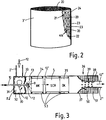
- FIG. 2 An embodiment of an evaporator 3 'is shown in detail in FIG. 2.
- the evaporator consists of a plurality of essentially longitudinal channels 20 with a small diameter of about 1 or 2 millimeters. As shown in detail at the interface, the channels 20 do not run in a straight line, but with deflections 21 which follow one another at short intervals.
- the Walls 22 of the channels 20 consist of thin sheet metal which is provided with openings or bores 23 which allow partial flows from one channel into the adjacent channel.
- the openings 23 shown in the straight sections of the channels 20 according to FIG. 2 can also be provided in the deflection points 21, whereby a separation of a gas thread at one point and the connection of gas threads at other points can be even more effective.
- Evaporators of this type can be produced, for example, from a rolled-up, profiled sheet with corresponding openings.
- the formed with a variety of thin channels or in the manner of the evaporator 3 hydrolysis catalyst 4 contains as an active component finely divided mixtures of metal oxides, for.
- the active component can be used at a space velocity of over 30,000 h ⁇ 1 at least between 240 ° and 650 ° C.
- the evaporator and the hydrolysis catalytic converter are preferably also produced as one component, as is indicated in FIG. 3 by reference number 34.
- an evaporator designed as a flow mixer approximately as shown in FIG. 2, could be used, the channel walls 22 of which are provided with a catalytically active coating of metal oxides, as described above.
- a porous coating supports the hydrolysis process.
- a pressure atomizing nozzle 9 is provided, into which compressed air and urea solution 6 enter via a supply line 10.
- the compressed air line 11 opens as close as possible to the urea solution container 7 in the feed line 10 in order to prepare the longest possible emulsification path which ensures sufficient mixing of the compressed gas with the urea solution 6.
- a line 11 ′ branches off with a pressure control valve 13 for the urea solution container 7 designed as a pressure container.
- FIG. 1 shows a simple embodiment in which the pressure atomizing nozzle 9 is arranged in the center of the straight-line exhaust gas line 2 and the exhaust gas 12 flows around it.
- the solution mist 13 is entrained directly by the exhaust gas flow and brought into the evaporator 3.
- FIG. 3 another arrangement is provided which enables the exhaust gases 12 to be mixed with the solution mist 13 before entering the evaporator or hydrolysis catalytic converter 34.
- the hyrolysis catalyst 34 is located in a cylindrical housing 30, through the end face 31 of which the emulsifying line 10 with the pressure atomizing nozzle 9 projects into a prechamber 32.
- the exhaust gas 12 is introduced tangentially into the prechamber 32.
- the swirl in the exhaust gas caused thereby is reinforced by a swirl disk 33 which divides the antechamber 32 into two areas.
- the exhaust gas 12 reaches the area of the prechamber 32 facing away from the hydrolysis catalytic converter and then flows through the swirl disk 33 into the second area of the prechamber 32, in which the pressure atomizing nozzle 9 is located.
- the swirling movement of the exhaust gas 12 swirls the partially evaporated droplets of the solvent mist 13 and mixed in with the exhaust gas. This mixture then enters the hydrolysis catalyst 34.
- the reduction catalyst 5 and an oxidation catalyst 35 which are connected in series, are arranged in the housing 31 after the hydrolysis catalyst 34.
- a sound absorption damper 36 is integrated in the housing 31, which is designed as a funnel-shaped outlet pipe 37 and is provided with bores 38, through which partial flows 39 can get into an expansion space 50 during vibrations in the exhaust gas, which expansion space 50 can be filled, for example, with a steel mesh 51.
- the cleaned exhaust gas 12 ′′ is thus passed on via a again narrowed pipe section 2 ′′ or discharged into the open, the cross section of which corresponds to the cross section of the input exhaust pipe 2 ′. Sound insulation can also take place before the exhaust gas 12 is mixed with the urea solution 13.
- the pre-chamber 32 is lined with a sound-absorbing insert.
- the mixed with ammonia and CO2 exhaust gas 12 'passes from the hydrolysis catalyst 34 in the SCR catalyst 5, in which the NO x is reduced in a known manner.
- a control system 15 (FIG. 1) is provided, which controls a solenoid valve 16 for a controlled metering of the urea solution supply as a function of not only the engine speed n but also the engine load.
- the urea supply is metered according to the need, ie the respective NO x content in the exhaust gas, so that the ammonia released by hydrolysis is completely used up in the reduction process.
- the control process is also influenced by the signals from two temperature sensors 17 and 18, which monitor the exhaust gas temperature in the area of the pollutant conversion. If one of the temperature sensors 17, 18 signals a temperature below a predetermined value, below which a complete conversion of the urea solution into ammonia is not possible, the supply of urea solution 6 is stopped until the required temperature prevails again in the exhaust system.
- Another measure that supports the proper operation of the system is the coating of the prechamber walls 32, which comes into contact with the urea solution, with a material that is caused by heat conduction and by means of an active component according to claims 9 and 10, the attachment of urea crystals by them timely evaporation and hydrolysis prevented.
- thermal insulation measures on the housing 30 and heating options of the spray nozzle 9 and / or other components can also be assigned. Heating the emulsifying line 10 and the pressure atomizing nozzle 9 prevents small urea crystals, in particular, from becoming lodged in the nozzle.
- FIG. 4 and 5 is a further embodiment of gas mixing by means of a conical guide plate 40, into the narrow side of which the spray nozzle 9 projects and around which the exhaust gas 12 flows.
- the baffle 40 has a multiplicity of bores 41 through which the exhaust gas which flows into the housing 31 through the line 2 ′ reaches the inner region 42 of the baffle.
- There is a pressure difference between the outer and inner areas of the guide plate 40 ⁇ p p1 - p2 , which causes a partial exhaust jet velocity Va.
- the individual exhaust jets pierce the urea / atomizing air cone 44 and mix it downstream with the exhaust gas.
- the mixing of urea solution into the exhaust gas can be controlled by selecting the diameter and the distance a between the bores 41 and the distribution between the spray nozzle 9 and the hydrolysis catalytic converter 34.
- FIG. 6 A variant of this is shown in FIG. 6, in which an approximately conical mixing device 60 has three rows of guide slots 61 to 63, which are each regularly distributed over the circumference of the areas m, n, o of the mixing device 60.
- the exhaust gas 12 receives a swirl which in the first area m and in the third area o the exhaust gas jets 64 and 65 in the direction of the input swirl reinforced, while the guide plates 62 cause a swirl reversal in the central region n of the mixing device 60.
- FIG. 6A shows a cross section through the central region n, the guide slots or guide plates 62 of which are distributed over the circumference causing a reversal of the flow of the exhaust gas partial flows 66.
- the inwardly directed baffles 63 and 61 are directed so that the exhaust gas partial flows 67 maintain their original flow direction.
- the swirl reversal causes strong turbulence in the area between the spray nozzle and the hydrolysis catalytic converter 34. These lead to the mixing of the urea solution air mist into the exhaust gas flow.
- the mixing process can be intensified by repeated swirl reversal.
- FIG. 7 A further variant is shown in FIG. 7, in which a funnel-shaped mixing device 70 is provided with numerous inlets 71, each of which has a plurality of guide plates 72, which cause a swirl of an incoming individual jet 73.
- the baffles 72 are each arranged in a radiation pattern, so that a large number of small exhaust gas eddy currents 73 flow into the inner region 74 of the mixing device 70 and cause strong turbulence, which bring about a good mixing between exhaust gas and urea solution mist.
- the baffles are about dividing the exhaust gases into numerous accelerated and / or swirled partial flows. Combinations can also be used in which partial flows accelerate according to FIG. 5 and other partial flows are swirled according to FIG. 7.
- a metal carrier honeycomb of a slotted type with cross-current generation (FIG. 2, cell division 150 cpsi, length 43 mm) coated with a mixture of metal oxides (composition A, Table 1) is filled with 18.8 ml / h urea water solution ( 32.5 wt .-%) sprayed from an adjustable micro nozzle by means of a pump, while a gas mixture of O2 (8%), HC (200 ppm C1), CO (100 ppm), SO2 (20 ppm), water vapor ( 5%) flows over the catalyst.
- the total space velocity of the Gas mixture (2480 l / h) was 60,000 h ⁇ 1.
- the gas mixture flowed for analysis through an FTIR long-path cell heated to 110 ° C (2 m optical path length).
- the FTIR spectrum shows the formation of NH3 (2000 ppm) and CO2 (1000 ppm) in a molar ratio of 2: 1 corresponding to a complete hydrolysis of the urea to CO (NH2) 2 + H2O ⁇ 2NH3 + CO2 in the temperature range from 160 to 600 ° C .
- the gas mixture was passed through a 4 ° cooler after leaving the catalyst and the sublimate at the cooler inlet and the condensate were quantitatively analyzed.
- the sublimate consisted of 5-10 mg urea at all temperatures. A urea conversion of ⁇ 99.97% was realized.
- the embodiment 1 was repeated.
- a free-pass metal carrier honeycomb of the standard type coated with a mixture of metal oxides (composition A, Table 1) with parallel channels with 200 cpsi, length 43 mm was used and the experiments for catalytic urea hydrolysis were repeated under otherwise identical test conditions.
- an NH3 / CO2 molar ratio of 2: 1 was observed within the measurement accuracy of the FTIR spectrometer.
- a urea slip was observed in the long-term tests, which reflected slightly reduced urea conversions (200 °: 96.8%, 300 °: 98.4%, 400 °: 99.6%).
- the embodiment 1 was repeated.
- the FTIR spectrum shows the occurrence of HNCO in addition to the gases NH3 and CO2. Urea turnover drops massively (200 °: 68%, 300 °: 79%, 400: 83%).
- Example 1 The experiment described in Example 1 was repeated under the same conditions with the coatings having the composition BE (Table 1). In all cases a urine metabolism conversion of ⁇ 99.95% was measured.
- the result of the exhaust gas aftertreatment was found to be 3.2 g NO x / kWh (71%), 0.9 g CO / kWh (74%), 0.22 g HC / kWh (80%).
- Extraction of the particles with hot H2O / isopropanoI and gravimetric determination of the urea using the xanthydrol method show a urea slip of 2 mg / kWh. This low value shows that the urea slip cannot cause a measurable increase in the particle mass.
- No deposits of urea or urea reaction products were found in the area of the catalyst inlet.
- the injection of the reducing agent urea water was above a minimum exhaust gas temperature (17, 18) of 250 ° C, with the x for a NO cleardown of 75% equivalent amount of urea water.
- a metal carrier honeycomb (Fig. 2, 150 cpsi) ⁇ 35 mm, length 43 mm is by immersion in an aqueous 25% by weight suspension of Al2O3, -SiO2 and ZrO2 (weight ratio 12: 4: 1, composition A) and blowing out the Excess coating material with a coating. It is dried at 120 ° C. and calcined at 700 ° C. for 5 hours. The same procedure is followed for mixtures B - E.
Landscapes
- Chemical & Material Sciences (AREA)
- Engineering & Computer Science (AREA)
- Chemical Kinetics & Catalysis (AREA)
- Health & Medical Sciences (AREA)
- Combustion & Propulsion (AREA)
- Analytical Chemistry (AREA)
- Oil, Petroleum & Natural Gas (AREA)
- General Chemical & Material Sciences (AREA)
- Biomedical Technology (AREA)
- Environmental & Geological Engineering (AREA)
- Toxicology (AREA)
- General Engineering & Computer Science (AREA)
- Mechanical Engineering (AREA)
- Exhaust Gas After Treatment (AREA)
- Exhaust Gas Treatment By Means Of Catalyst (AREA)
Applications Claiming Priority (2)
| Application Number | Priority Date | Filing Date | Title |
|---|---|---|---|
| DE4203807A DE4203807A1 (de) | 1990-11-29 | 1992-02-10 | Vorrichtung zur katalytischen no(pfeil abwaerts)x(pfeil abwaerts)-reduktion |
| DE4203807 | 1992-02-10 |
Publications (2)
| Publication Number | Publication Date |
|---|---|
| EP0555746A1 true EP0555746A1 (fr) | 1993-08-18 |
| EP0555746B1 EP0555746B1 (fr) | 1997-09-10 |
Family
ID=6451323
Family Applications (1)
| Application Number | Title | Priority Date | Filing Date |
|---|---|---|---|
| EP93101624A Expired - Lifetime EP0555746B1 (fr) | 1992-02-10 | 1993-02-03 | Dispositif pour la réduction catalytique de NOx |
Country Status (3)
| Country | Link |
|---|---|
| EP (1) | EP0555746B1 (fr) |
| AT (1) | ATE157901T1 (fr) |
| DE (1) | DE59307293D1 (fr) |
Cited By (76)
| Publication number | Priority date | Publication date | Assignee | Title |
|---|---|---|---|---|
| WO1996004980A1 (fr) * | 1994-08-10 | 1996-02-22 | Siemens Aktiengesellschaft | Procede de conversion catalytique d'oxydes d'azote contenus dans les gaz d'echappement d'un moteur a combustion interne |
| WO1997007876A3 (fr) * | 1995-08-23 | 1997-04-17 | Siemens Ag | Procede et dispositif pour la decomposition des oxydes d'azote contenus dans les gaz d'echappement d'un moteur a combustion interne |
| FR2755624A1 (fr) * | 1996-11-12 | 1998-05-15 | Daimler Benz Ag | Systeme d'injection de reducteur d'oxyde d'azote dans un flux de gaz d'echappement |
| EP0848985A1 (fr) * | 1996-12-10 | 1998-06-24 | Robert Bosch Gmbh | Procédé et dispositif pour la reduction d'oxydes d'azote des mélanges gazeux |
| EP0864732A1 (fr) * | 1997-03-13 | 1998-09-16 | Haldor Topsoe A/S | Procédé de réduction sélective de NOx dans les gaz d'échappement |
| WO1998052679A1 (fr) * | 1997-05-16 | 1998-11-26 | Siemens Aktiengesellschaft | Procede et dispositif pour eliminer des polluants de type oxyde dans un gaz d'echappement contenant de l'oxygene et moteur fonctionnant de façon correspondante |
| DE19734627C1 (de) * | 1997-08-09 | 1999-01-14 | Man Nutzfahrzeuge Ag | Vorrichtung und Verfahren zur katalytischen NO¶x¶-Reduktion in sauerstoffhaltigen Motorabgasen |
| EP0894523A1 (fr) * | 1997-07-28 | 1999-02-03 | Siemens Aktiengesellschaft | Mélangeur statique et tuyau de gaz d'échappement pour une installation de combustion |
| EP0900923A3 (fr) * | 1997-09-05 | 1999-09-29 | Robert Bosch Gmbh | Dispositif de distribution d'un mélange |
| EP0905356A3 (fr) * | 1997-09-30 | 1999-11-03 | Siemens Aktiengesellschaft | Système de réduction de NOx avec dispositif de dosage d' agent de réduction |
| WO1999058230A1 (fr) * | 1998-05-11 | 1999-11-18 | Siemens Aktiengesellschaft | Procede et dispositif pour la reduction catalytique selective d'oxydes d'azote dans un milieu gazeux renfermant de l'oxygene |
| WO1999056858A3 (fr) * | 1998-04-30 | 2000-01-06 | Siemens Ag | Procede et dispositif pour la reduction catalytique des oxydes d'azote |
| EP0975417A4 (fr) * | 1997-04-02 | 2000-02-02 | Clean Diesel Tech Inc | REDUCTION DES EMISSIONS DE NOx EMANANT D'UN MOTEUR PAR INJECTION D'UREE REGULEE |
| WO2000008314A1 (fr) * | 1998-07-31 | 2000-02-17 | Alfred Buck | Systeme d'echappement comportant un dispositif de reduction catalytique de nox et un element support de pot catalytique a base de fibres |
| DE19901915C1 (de) * | 1999-01-19 | 2000-04-20 | Siemens Ag | Verfahren zur katalytischen Umsetzung von im Abgas eines Verbrennungsmotors enthaltenen Stickoxiden |
| EP1022048A1 (fr) * | 1999-01-21 | 2000-07-26 | Man Nutzfahrzeuge Ag | Procédé et dispositif de dosage d'un agent de réduction |
| GB2353234A (en) * | 1999-08-16 | 2001-02-21 | Ford Global Tech Inc | On-board reductant delivery system |
| WO2001012301A1 (fr) * | 1999-08-17 | 2001-02-22 | Emitec Gesellschaft Für Emissionstechnologie Mbh | Dispositif permettant de reduire la teneur en azote dans un gaz d'echappement issu d'un moteur a combustion interne |
| EP1096116A2 (fr) | 1999-10-30 | 2001-05-02 | MAN Nutzfahrzeuge Aktiengesellschaft | Procédé et dispositif combinant la réduction catalytique de NOx et l'amortissement de son de gaz d' échappement dans la ligne d'échappement d'un moteur à combustion interne |
| GB2363084A (en) * | 2000-06-05 | 2001-12-12 | Ford Global Tech Inc | Exhaust gas purification system |
| EP1260682A1 (fr) * | 2001-05-14 | 2002-11-27 | MAN Nutzfahrzeuge Aktiengesellschaft | Ligne d'échappement d'un moteur à combustion interne, plus particulièrement d'un moteur diesel d'un véhicule utilitaire tel qu'un poids lourd ou un bus, comportant un dispositif de traitement des gaz d'échappement et d'insonorisation intégré |
| WO2003036056A1 (fr) * | 2001-10-25 | 2003-05-01 | Eminox Limited | Appareil de traitement de gaz |
| EP1262644A3 (fr) * | 2001-06-01 | 2003-08-06 | Nelson Burgess Limited | Convertisseur catalytique |
| DE10206028A1 (de) * | 2002-02-14 | 2003-08-28 | Man Nutzfahrzeuge Ag | Verfahren und Vorrichtung zur Erzeugung von Ammoniak |
| EP1338770A3 (fr) * | 2002-02-25 | 2004-10-27 | DaimlerChrysler AG | Dispositif de purification des gaz d'échappement d'un moteur à combustion thermique |
| EP1433933A3 (fr) * | 1996-06-10 | 2004-12-29 | Hitachi, Ltd. | Dispositif de purification des gaz d'échappement d'un moteur à combustion interne et catalyseur pour purifier les gaz d'échappement d'un moteur à combustion interne |
| WO2005025725A1 (fr) * | 2003-09-05 | 2005-03-24 | Robert Bosch Gmbh | Dispositif de traitement d'une solution produit semi-fini d'agent reducteur pour traitement posterieur de gaz d'echappement |
| WO2005073524A1 (fr) * | 2004-01-30 | 2005-08-11 | Robert Bosch Gmbh | Procede et dispositif de traitement posterieur de gaz d'echappement d'un moteur a combustion interne |
| US6941746B2 (en) | 2002-11-21 | 2005-09-13 | Combustion Components Associates, Inc. | Mobile diesel selective catalytic reduction systems and methods |
| WO2006010922A1 (fr) * | 2004-07-29 | 2006-02-02 | Eminox Limited | Appareil de traitement de gaz |
| FR2891305A1 (fr) * | 2005-09-27 | 2007-03-30 | Renault Sas | Ligne d'echappement de moteur de vehicule comprenant un injecteur de carburant |
| US7198763B2 (en) | 2001-09-01 | 2007-04-03 | Haldor Topsoe A/S | Method for distribution of gas, gas distributing device and silencer-catalyst system |
| WO2008043387A1 (fr) * | 2006-10-13 | 2008-04-17 | Mennen-Geenen G.C.M | Procédé d'élimination de composantes nox dans des gaz de combustion |
| KR100848940B1 (ko) | 2005-04-18 | 2008-07-29 | 디비케이 다비드 + 바더 게엠베하 | 요소의 가열 및 기화를 위한 가열 장치 및 열반응기 |
| WO2008144385A2 (fr) | 2007-05-15 | 2008-11-27 | Donaldson Company, Inc. | Dispositif d'écoulement de gaz d'échappement |
| EP2095866A1 (fr) * | 2008-02-25 | 2009-09-02 | JGC Catalysts and Chemicals Ltd. | appareil pour traiter un gaz d'échappement |
| WO2009118195A1 (fr) * | 2008-03-28 | 2009-10-01 | Süd-Chemie AG | Catalyseur d'hydrolyse de l'urée |
| WO2009131666A1 (fr) | 2008-04-25 | 2009-10-29 | Tenneco Automotive Operating Company, Inc. | Système de traitement/d’additif de gaz d’échappement et mélangeur utilisé dans celui-ci |
| WO2009154972A1 (fr) | 2008-05-27 | 2009-12-23 | Fuel Tech, Inc. | Processus et appareil de réduction catalytique sélective de no<sb>x</sb> procurant une gazéification améliorée de l'urée pour former un gaz contenant de l'ammoniac |
| FR2940921A1 (fr) * | 2009-01-12 | 2010-07-16 | Peugeot Citroen Automobiles Sa | Dispositif de traitement des gaz d'echappement d'un moteur |
| EP1915518B1 (fr) * | 2005-08-20 | 2010-12-15 | Technische Universität Kaiserslautern | Dispositif, reacteur et procede de reduction d'oxydes d'azote dans les gaz d'echappement de moteurs a combustion interne |
| CN102032030A (zh) * | 2009-09-25 | 2011-04-27 | 中国第一汽车集团公司 | 一种汽车尾气催化还原后处理器的复合单元 |
| WO2011073239A1 (fr) * | 2009-12-16 | 2011-06-23 | Iveco Motorenforschung Ag | Module de dosage pour doser un agent réducteur à base d'urée dans un flux de gaz d'échappement |
| WO2011073240A1 (fr) * | 2009-12-16 | 2011-06-23 | Iveco Motorenforschung Ag | Procédé pour doser un agent réducteur à base d'urée dans un flux de gaz d'échappement |
| WO2011110885A1 (fr) * | 2010-03-11 | 2011-09-15 | Renault Trucks | Système de mélange pour un agencement post-traitement de gaz d'échappement |
| EP2492465A1 (fr) * | 2011-02-25 | 2012-08-29 | Peugeot Citroën Automobiles SA | Dispositif de protection d'un injecteur de réducteur |
| US8429900B2 (en) | 2003-04-29 | 2013-04-30 | Man Truck & Bus Ag | Liquid container for motor vehicles |
| EP2607641A1 (fr) * | 2011-12-19 | 2013-06-26 | Mtu Friedrichshafen Gmbh | Dispositif de mélange pour l'introduction d'un agent de réduction dans un flux de gaz d'échappement avec des éléments en forme d'aube |
| CN103184915A (zh) * | 2011-12-29 | 2013-07-03 | 广西玉柴机器股份有限公司 | 螺旋式添蓝混合器 |
| JP2013136991A (ja) * | 2011-12-28 | 2013-07-11 | Hino Motors Ltd | 排気浄化装置 |
| US8499548B2 (en) | 2008-12-17 | 2013-08-06 | Donaldson Company, Inc. | Flow device for an exhaust system |
| WO2013121112A1 (fr) | 2012-02-17 | 2013-08-22 | Ecocat Oy | Revêtement pour réduire les oxydes d'azote |
| US8539761B2 (en) | 2010-01-12 | 2013-09-24 | Donaldson Company, Inc. | Flow device for exhaust treatment system |
| US8776499B2 (en) | 2008-02-25 | 2014-07-15 | Basf Corporation | Emission treatment systems and methods using passivated surfaces |
| US8793978B2 (en) | 2011-02-04 | 2014-08-05 | Caterpillar Inc. | Exhaust system having thermally conductive dosing channel |
| EP2676723A3 (fr) * | 2012-06-20 | 2014-08-06 | CNH Industrial Italia S.p.A. | Système d'échappement pour véhicule agricole |
| US8938954B2 (en) | 2012-04-19 | 2015-01-27 | Donaldson Company, Inc. | Integrated exhaust treatment device having compact configuration |
| CN104797529A (zh) * | 2012-12-21 | 2015-07-22 | 澳泽化学股份公司 | 氨气发生器、用于产生氨的方法及其用于还原废气中的氮氧化物的用途 |
| US9267417B2 (en) | 2013-10-31 | 2016-02-23 | Faurecia Emissions Control Technologies Usa, Llc | Diffuser plate |
| US9291081B2 (en) | 2013-05-07 | 2016-03-22 | Tenneco Automotive Operating Company Inc. | Axial flow atomization module |
| US9289724B2 (en) | 2013-05-07 | 2016-03-22 | Tenneco Automotive Operating Company Inc. | Flow reversing exhaust gas mixer |
| US9314750B2 (en) | 2013-05-07 | 2016-04-19 | Tenneco Automotive Operating Company Inc. | Axial flow atomization module |
| US9334781B2 (en) | 2013-05-07 | 2016-05-10 | Tenneco Automotive Operating Company Inc. | Vertical ultrasonic decomposition pipe |
| US9352276B2 (en) | 2013-05-07 | 2016-05-31 | Tenneco Automotive Operating Company Inc. | Exhaust mixing device |
| US9364790B2 (en) | 2013-05-07 | 2016-06-14 | Tenneco Automotive Operating Company Inc. | Exhaust mixing assembly |
| US9534525B2 (en) | 2015-05-27 | 2017-01-03 | Tenneco Automotive Operating Company Inc. | Mixer assembly for exhaust aftertreatment system |
| US9670811B2 (en) | 2010-06-22 | 2017-06-06 | Donaldson Company, Inc. | Dosing and mixing arrangement for use in exhaust aftertreatment |
| US9707525B2 (en) | 2013-02-15 | 2017-07-18 | Donaldson Company, Inc. | Dosing and mixing arrangement for use in exhaust aftertreatment |
| CN108979803A (zh) * | 2018-07-25 | 2018-12-11 | 武汉水草能源科技研发中心(有限合伙) | 液体与气体混合的方法及装置 |
| CN110073087A (zh) * | 2016-12-21 | 2019-07-30 | 珀金斯发动机有限公司 | 用于选择性催化还原系统的方法和装置 |
| CN110073089A (zh) * | 2016-12-21 | 2019-07-30 | 珀金斯发动机有限公司 | 用于选择性催化还原系统的方法 |
| EP3561249A1 (fr) | 2016-04-13 | 2019-10-30 | Roth Technik Austria Gesellschaft Mit Beschränkter Haftung | Dispositif de post-traitement des gaz d'échappement doté d'un catalyseur et d'un dispositif de mélange |
| CN110418876A (zh) * | 2017-04-07 | 2019-11-05 | 珀金斯发动机有限公司 | 改进的选择性催化还原系统和方法 |
| US10844764B2 (en) | 2014-01-31 | 2020-11-24 | Donaldson Company, Inc. | Dosing and mixing arrangement for use in exhaust aftertreatment |
| CN115898598A (zh) * | 2023-02-08 | 2023-04-04 | 中国船舶重工集团柴油机有限公司 | 一种高压scr蒸发混合装置及使用方法 |
| US11753979B2 (en) | 2019-08-22 | 2023-09-12 | Cummins Emission Solutions Inc. | Systems and methods for generating ammonia |
Families Citing this family (12)
| Publication number | Priority date | Publication date | Assignee | Title |
|---|---|---|---|---|
| DE19922959A1 (de) | 1999-05-19 | 2000-11-23 | Daimler Chrysler Ag | Abgasreinigungsanlage mit Stickoxidreduktion unter Reduktionsmittelzugabe |
| DE10340467B4 (de) | 2003-09-03 | 2012-10-04 | Man Truck & Bus Ag | Vorrichtung zur Führung eines fließfähigen Mediums |
| US7963104B2 (en) | 2008-02-15 | 2011-06-21 | Ford Global Technologies, Llc | Emission control system having a coated mixer for an internal combustion engine and method of use |
| DE102008017279A1 (de) | 2008-04-04 | 2009-10-08 | Man Nutzfahrzeuge Ag | Verfahren zur Anhebung des Stickstoffdioxidanteils im Abgas |
| DE102008046994B4 (de) | 2008-09-12 | 2015-02-12 | Süd-Chemie Ip Gmbh & Co. Kg | Harnstoff-Hydrolyse-Katalysator |
| DE102008048426A1 (de) | 2008-09-23 | 2010-04-01 | Man Nutzfahrzeuge Aktiengesellschaft | Dosiervorrichtung zur Zudosierung eines Reduktionsmittels, insbesondere für eine selektive katalytische Reduktion, in einen Abgasstrom einer Brennkraftmaschine |
| DE102009035692A1 (de) | 2009-07-30 | 2011-02-03 | Man Nutzfahrzeuge Ag | Verfahren und Vorrichtung zur Reinigung eines Abgasstroms einer abgasaufgeladenen Brennkraftmaschine |
| DE102009035693A1 (de) | 2009-07-30 | 2011-02-10 | Man Nutzfahrzeuge Ag | Verfahren und Vorrichtung zur Reinigung eines Abgasstroms einer Brennkraftmaschine |
| DE202013006962U1 (de) | 2013-08-05 | 2013-08-28 | Tenneco Gmbh | Mischkammer |
| US9784163B2 (en) | 2015-01-22 | 2017-10-10 | Tenneco Automotive Operating Company Inc. | Exhaust aftertreatment system having mixer assembly |
| DE102015103425B3 (de) | 2015-03-09 | 2016-05-19 | Tenneco Gmbh | Mischvorrichtung |
| WO2018077390A1 (fr) | 2016-10-25 | 2018-05-03 | Doosan Lentjes Gmbh | Cyclone doté de moyens pour introduire un agent réducteur |
Citations (7)
| Publication number | Priority date | Publication date | Assignee | Title |
|---|---|---|---|---|
| US3716344A (en) * | 1971-02-10 | 1973-02-13 | New Prod Corp | Internal combustion engine exhaust catalytic reactor |
| DE3729994A1 (de) * | 1987-09-08 | 1989-03-16 | Bischoff Erhardt Gmbh Co Kg | Vorrichtung zum katalytischen reinigen von abgasen |
| DE3830045A1 (de) * | 1988-09-03 | 1990-03-15 | Bayer Ag | Verfahren zur reduktion von in abgasen enthaltenen stickoxiden mittels eines zeolithhaltigen katalysators |
| EP0468919A1 (fr) * | 1990-07-27 | 1992-01-29 | New Sulzer Diesel Ag | Gros moteur diesel |
| WO1992002291A1 (fr) * | 1990-08-01 | 1992-02-20 | Nalco Fuel Tech Gmbh | Procede d'hydrolyse de l'uree dans une canalisation |
| DE4032085A1 (de) * | 1990-10-10 | 1992-04-16 | Didier Werke Ag | Katalysatoranordnung zur reduktion von stickoxiden |
| DE4038054A1 (de) * | 1990-11-29 | 1992-06-04 | Man Technologie Gmbh | Verfahren und vorrichtung zur selektiven katalytischen no(pfeil abwaerts)x(pfeil abwaerts)-reduktion in sauerstoffhaltigen abgasen |
-
1993
- 1993-02-03 EP EP93101624A patent/EP0555746B1/fr not_active Expired - Lifetime
- 1993-02-03 DE DE59307293T patent/DE59307293D1/de not_active Expired - Lifetime
- 1993-02-03 AT AT93101624T patent/ATE157901T1/de not_active IP Right Cessation
Patent Citations (7)
| Publication number | Priority date | Publication date | Assignee | Title |
|---|---|---|---|---|
| US3716344A (en) * | 1971-02-10 | 1973-02-13 | New Prod Corp | Internal combustion engine exhaust catalytic reactor |
| DE3729994A1 (de) * | 1987-09-08 | 1989-03-16 | Bischoff Erhardt Gmbh Co Kg | Vorrichtung zum katalytischen reinigen von abgasen |
| DE3830045A1 (de) * | 1988-09-03 | 1990-03-15 | Bayer Ag | Verfahren zur reduktion von in abgasen enthaltenen stickoxiden mittels eines zeolithhaltigen katalysators |
| EP0468919A1 (fr) * | 1990-07-27 | 1992-01-29 | New Sulzer Diesel Ag | Gros moteur diesel |
| WO1992002291A1 (fr) * | 1990-08-01 | 1992-02-20 | Nalco Fuel Tech Gmbh | Procede d'hydrolyse de l'uree dans une canalisation |
| DE4032085A1 (de) * | 1990-10-10 | 1992-04-16 | Didier Werke Ag | Katalysatoranordnung zur reduktion von stickoxiden |
| DE4038054A1 (de) * | 1990-11-29 | 1992-06-04 | Man Technologie Gmbh | Verfahren und vorrichtung zur selektiven katalytischen no(pfeil abwaerts)x(pfeil abwaerts)-reduktion in sauerstoffhaltigen abgasen |
Cited By (130)
| Publication number | Priority date | Publication date | Assignee | Title |
|---|---|---|---|---|
| WO1996004980A1 (fr) * | 1994-08-10 | 1996-02-22 | Siemens Aktiengesellschaft | Procede de conversion catalytique d'oxydes d'azote contenus dans les gaz d'echappement d'un moteur a combustion interne |
| US5974789A (en) * | 1995-08-23 | 1999-11-02 | Siemens Aktiengesellschaft | Method and device for decomposing nitrogen oxides in the exhaust gas of an internal combustion engine |
| WO1997007876A3 (fr) * | 1995-08-23 | 1997-04-17 | Siemens Ag | Procede et dispositif pour la decomposition des oxydes d'azote contenus dans les gaz d'echappement d'un moteur a combustion interne |
| US7093432B2 (en) | 1996-06-10 | 2006-08-22 | Hitachi, Ltd. | Exhaust gas purification apparatus of internal combustion engine and catalyst for purifying exhaust gas of internal combustion engine |
| EP1433933A3 (fr) * | 1996-06-10 | 2004-12-29 | Hitachi, Ltd. | Dispositif de purification des gaz d'échappement d'un moteur à combustion interne et catalyseur pour purifier les gaz d'échappement d'un moteur à combustion interne |
| FR2755624A1 (fr) * | 1996-11-12 | 1998-05-15 | Daimler Benz Ag | Systeme d'injection de reducteur d'oxyde d'azote dans un flux de gaz d'echappement |
| EP0848985A1 (fr) * | 1996-12-10 | 1998-06-24 | Robert Bosch Gmbh | Procédé et dispositif pour la reduction d'oxydes d'azote des mélanges gazeux |
| EP0864732A1 (fr) * | 1997-03-13 | 1998-09-16 | Haldor Topsoe A/S | Procédé de réduction sélective de NOx dans les gaz d'échappement |
| EP0975417A4 (fr) * | 1997-04-02 | 2000-02-02 | Clean Diesel Tech Inc | REDUCTION DES EMISSIONS DE NOx EMANANT D'UN MOTEUR PAR INJECTION D'UREE REGULEE |
| WO1998052679A1 (fr) * | 1997-05-16 | 1998-11-26 | Siemens Aktiengesellschaft | Procede et dispositif pour eliminer des polluants de type oxyde dans un gaz d'echappement contenant de l'oxygene et moteur fonctionnant de façon correspondante |
| EP0894523A1 (fr) * | 1997-07-28 | 1999-02-03 | Siemens Aktiengesellschaft | Mélangeur statique et tuyau de gaz d'échappement pour une installation de combustion |
| EP0896831A1 (fr) * | 1997-08-09 | 1999-02-17 | MAN Nutzfahrzeuge Aktiengesellschaft | Dispositif et procédé pour la réduction de NOx dans les gaz d'échappement de moteurs contenant d'oxygène |
| DE19734627C1 (de) * | 1997-08-09 | 1999-01-14 | Man Nutzfahrzeuge Ag | Vorrichtung und Verfahren zur katalytischen NO¶x¶-Reduktion in sauerstoffhaltigen Motorabgasen |
| EP0900923A3 (fr) * | 1997-09-05 | 1999-09-29 | Robert Bosch Gmbh | Dispositif de distribution d'un mélange |
| EP0905356A3 (fr) * | 1997-09-30 | 1999-11-03 | Siemens Aktiengesellschaft | Système de réduction de NOx avec dispositif de dosage d' agent de réduction |
| US6082102A (en) * | 1997-09-30 | 2000-07-04 | Siemens Aktiengesellschaft | NOx reduction system with a device for metering reducing agents |
| WO1999056858A3 (fr) * | 1998-04-30 | 2000-01-06 | Siemens Ag | Procede et dispositif pour la reduction catalytique des oxydes d'azote |
| WO1999058230A1 (fr) * | 1998-05-11 | 1999-11-18 | Siemens Aktiengesellschaft | Procede et dispositif pour la reduction catalytique selective d'oxydes d'azote dans un milieu gazeux renfermant de l'oxygene |
| US6878359B1 (en) | 1998-05-11 | 2005-04-12 | Siemens Aktiengesellschaft | Process and device for the selective catalytic reduction of nitrogen oxides in an oxygen-containing gaseous medium |
| WO2000008314A1 (fr) * | 1998-07-31 | 2000-02-17 | Alfred Buck | Systeme d'echappement comportant un dispositif de reduction catalytique de nox et un element support de pot catalytique a base de fibres |
| DE19901915C1 (de) * | 1999-01-19 | 2000-04-20 | Siemens Ag | Verfahren zur katalytischen Umsetzung von im Abgas eines Verbrennungsmotors enthaltenen Stickoxiden |
| EP1022048A1 (fr) * | 1999-01-21 | 2000-07-26 | Man Nutzfahrzeuge Ag | Procédé et dispositif de dosage d'un agent de réduction |
| GB2353234A (en) * | 1999-08-16 | 2001-02-21 | Ford Global Tech Inc | On-board reductant delivery system |
| US6293097B1 (en) | 1999-08-16 | 2001-09-25 | Ford Global Technologies, Inc. | On-board reductant delivery system |
| GB2353234B (en) * | 1999-08-16 | 2003-06-25 | Ford Global Tech Inc | On-board reductant delivery system |
| WO2001012301A1 (fr) * | 1999-08-17 | 2001-02-22 | Emitec Gesellschaft Für Emissionstechnologie Mbh | Dispositif permettant de reduire la teneur en azote dans un gaz d'echappement issu d'un moteur a combustion interne |
| RU2219987C2 (ru) * | 1999-08-17 | 2003-12-27 | Эмитек Гезельшафт Фюр Эмиссионстехнологи Мбх | Устройство для снижения содержания оксидов азота в отработанных газах двигателя внутреннего сгорания |
| EP1096116A2 (fr) | 1999-10-30 | 2001-05-02 | MAN Nutzfahrzeuge Aktiengesellschaft | Procédé et dispositif combinant la réduction catalytique de NOx et l'amortissement de son de gaz d' échappement dans la ligne d'échappement d'un moteur à combustion interne |
| GB2363084A (en) * | 2000-06-05 | 2001-12-12 | Ford Global Tech Inc | Exhaust gas purification system |
| EP1260682A1 (fr) * | 2001-05-14 | 2002-11-27 | MAN Nutzfahrzeuge Aktiengesellschaft | Ligne d'échappement d'un moteur à combustion interne, plus particulièrement d'un moteur diesel d'un véhicule utilitaire tel qu'un poids lourd ou un bus, comportant un dispositif de traitement des gaz d'échappement et d'insonorisation intégré |
| EP1262644A3 (fr) * | 2001-06-01 | 2003-08-06 | Nelson Burgess Limited | Convertisseur catalytique |
| US7198763B2 (en) | 2001-09-01 | 2007-04-03 | Haldor Topsoe A/S | Method for distribution of gas, gas distributing device and silencer-catalyst system |
| WO2003036056A1 (fr) * | 2001-10-25 | 2003-05-01 | Eminox Limited | Appareil de traitement de gaz |
| DE10206028A1 (de) * | 2002-02-14 | 2003-08-28 | Man Nutzfahrzeuge Ag | Verfahren und Vorrichtung zur Erzeugung von Ammoniak |
| EP1338770A3 (fr) * | 2002-02-25 | 2004-10-27 | DaimlerChrysler AG | Dispositif de purification des gaz d'échappement d'un moteur à combustion thermique |
| US6941746B2 (en) | 2002-11-21 | 2005-09-13 | Combustion Components Associates, Inc. | Mobile diesel selective catalytic reduction systems and methods |
| US8429900B2 (en) | 2003-04-29 | 2013-04-30 | Man Truck & Bus Ag | Liquid container for motor vehicles |
| WO2005025725A1 (fr) * | 2003-09-05 | 2005-03-24 | Robert Bosch Gmbh | Dispositif de traitement d'une solution produit semi-fini d'agent reducteur pour traitement posterieur de gaz d'echappement |
| WO2005073524A1 (fr) * | 2004-01-30 | 2005-08-11 | Robert Bosch Gmbh | Procede et dispositif de traitement posterieur de gaz d'echappement d'un moteur a combustion interne |
| US7448206B2 (en) | 2004-01-30 | 2008-11-11 | Robert Bosch Gmbh | Method and apparatus for posttreatment of an exhaust gas from an internal combustion engine |
| WO2006010922A1 (fr) * | 2004-07-29 | 2006-02-02 | Eminox Limited | Appareil de traitement de gaz |
| GB2416718A (en) * | 2004-07-29 | 2006-02-08 | Eminox Ltd | Gas treatment apparatus |
| KR100848940B1 (ko) | 2005-04-18 | 2008-07-29 | 디비케이 다비드 + 바더 게엠베하 | 요소의 가열 및 기화를 위한 가열 장치 및 열반응기 |
| EP1915518B1 (fr) * | 2005-08-20 | 2010-12-15 | Technische Universität Kaiserslautern | Dispositif, reacteur et procede de reduction d'oxydes d'azote dans les gaz d'echappement de moteurs a combustion interne |
| FR2891305A1 (fr) * | 2005-09-27 | 2007-03-30 | Renault Sas | Ligne d'echappement de moteur de vehicule comprenant un injecteur de carburant |
| WO2008043387A1 (fr) * | 2006-10-13 | 2008-04-17 | Mennen-Geenen G.C.M | Procédé d'élimination de composantes nox dans des gaz de combustion |
| WO2008144385A2 (fr) | 2007-05-15 | 2008-11-27 | Donaldson Company, Inc. | Dispositif d'écoulement de gaz d'échappement |
| WO2008144385A3 (fr) * | 2007-05-15 | 2009-01-22 | Donaldson Co Inc | Dispositif d'écoulement de gaz d'échappement |
| US8915064B2 (en) | 2007-05-15 | 2014-12-23 | Donaldson Company, Inc. | Exhaust gas flow device |
| EP2546489A1 (fr) * | 2007-05-15 | 2013-01-16 | Donaldson Company, Inc. | Dispositif d'écoulement des gaz dýéchappement |
| EP2335812A1 (fr) * | 2008-02-25 | 2011-06-22 | JGC Catalysts and Chemicals Ltd. | Appareil pour traiter un gaz d'échappement |
| US8080209B2 (en) | 2008-02-25 | 2011-12-20 | Jgc Catalysts And Chemicals Ltd. | Exhaust gas treatment apparatus |
| EP2095866A1 (fr) * | 2008-02-25 | 2009-09-02 | JGC Catalysts and Chemicals Ltd. | appareil pour traiter un gaz d'échappement |
| US8776499B2 (en) | 2008-02-25 | 2014-07-15 | Basf Corporation | Emission treatment systems and methods using passivated surfaces |
| WO2009118195A1 (fr) * | 2008-03-28 | 2009-10-01 | Süd-Chemie AG | Catalyseur d'hydrolyse de l'urée |
| US8141353B2 (en) * | 2008-04-25 | 2012-03-27 | Tenneco Automotive Operating Company Inc. | Exhaust gas additive/treatment system and mixer for use therein |
| EP2268906A4 (fr) * | 2008-04-25 | 2014-05-07 | Tenneco Automotive Operating | Systeme de traitement/d'additif de gaz d'echappement et melangeur utilise dans celui-ci |
| WO2009131666A1 (fr) | 2008-04-25 | 2009-10-29 | Tenneco Automotive Operating Company, Inc. | Système de traitement/d’additif de gaz d’échappement et mélangeur utilisé dans celui-ci |
| WO2009154972A1 (fr) | 2008-05-27 | 2009-12-23 | Fuel Tech, Inc. | Processus et appareil de réduction catalytique sélective de no<sb>x</sb> procurant une gazéification améliorée de l'urée pour former un gaz contenant de l'ammoniac |
| EP2303431A4 (fr) * | 2008-05-27 | 2012-04-04 | Fuel Tech Inc | Processus et appareil de réduction catalytique sélective de no<sb>x</sb>procurant une gazéification améliorée de l'urée pour former un gaz contenant de l'ammoniac |
| US8499548B2 (en) | 2008-12-17 | 2013-08-06 | Donaldson Company, Inc. | Flow device for an exhaust system |
| US9925502B2 (en) | 2008-12-17 | 2018-03-27 | Donaldson Company, Inc. | Flow device for an exhaust system |
| US9180407B2 (en) | 2008-12-17 | 2015-11-10 | Donaldson Company, Inc. | Flow device for an exhaust system |
| FR2940921A1 (fr) * | 2009-01-12 | 2010-07-16 | Peugeot Citroen Automobiles Sa | Dispositif de traitement des gaz d'echappement d'un moteur |
| CN102032030A (zh) * | 2009-09-25 | 2011-04-27 | 中国第一汽车集团公司 | 一种汽车尾气催化还原后处理器的复合单元 |
| CN102032030B (zh) * | 2009-09-25 | 2015-04-22 | 中国第一汽车集团公司 | 一种汽车尾气催化还原后处理器的复合单元 |
| RU2560122C2 (ru) * | 2009-12-16 | 2015-08-20 | Фпт Моторенфоршунг Аг | Дозирующий модуль для дозированного введения восстановителя на основе мочевины в поток выхлопных газов |
| EP2339139A1 (fr) * | 2009-12-16 | 2011-06-29 | Iveco Motorenforschung AG | Procédé de dosage pour doser un agent de réduction à base d'urée dans un flux d'échappement de gaz |
| WO2011073240A1 (fr) * | 2009-12-16 | 2011-06-23 | Iveco Motorenforschung Ag | Procédé pour doser un agent réducteur à base d'urée dans un flux de gaz d'échappement |
| CN102652211B (zh) * | 2009-12-16 | 2015-11-25 | Fpt发动机研究公司 | 用于将尿素基还原剂喷射到排出气流中的喷射模块 |
| CN102652211A (zh) * | 2009-12-16 | 2012-08-29 | 依维柯发动机研究公司 | 用于将尿素基还原剂喷射到排出气流中的喷射模块 |
| CN102652210A (zh) * | 2009-12-16 | 2012-08-29 | 依维柯发动机研究公司 | 用于将尿素基还原剂喷射到排出气流中的方法 |
| CN102652210B (zh) * | 2009-12-16 | 2015-05-20 | Fpt发动机研究公司 | 用于将尿素基还原剂喷射到排出气流中的方法 |
| WO2011073239A1 (fr) * | 2009-12-16 | 2011-06-23 | Iveco Motorenforschung Ag | Module de dosage pour doser un agent réducteur à base d'urée dans un flux de gaz d'échappement |
| EP2339137A1 (fr) * | 2009-12-16 | 2011-06-29 | Iveco Motorenforschung AG | Module de dosage pour doser un agent de réduction à base d'urée dans un flux d'échappement de gaz |
| US8752365B2 (en) | 2009-12-16 | 2014-06-17 | Iveco Motorenforschung Ag | Method for dosing an urea based reducing agent into a gas exhaust stream |
| US8756918B2 (en) | 2009-12-16 | 2014-06-24 | Iveco Motorenforschung Ag | Dosing module for dosing an urea based reducing agent into a gas exhaust stream |
| RU2557055C2 (ru) * | 2009-12-16 | 2015-07-20 | Фпт Моторенфоршунг Аг | Способ дозирования восстановителя на основе мочевины в поток отработавшего газа |
| US8539761B2 (en) | 2010-01-12 | 2013-09-24 | Donaldson Company, Inc. | Flow device for exhaust treatment system |
| US9810126B2 (en) | 2010-01-12 | 2017-11-07 | Donaldson Company, Inc. | Flow device for exhaust treatment system |
| WO2011110885A1 (fr) * | 2010-03-11 | 2011-09-15 | Renault Trucks | Système de mélange pour un agencement post-traitement de gaz d'échappement |
| US9670811B2 (en) | 2010-06-22 | 2017-06-06 | Donaldson Company, Inc. | Dosing and mixing arrangement for use in exhaust aftertreatment |
| US10294841B2 (en) | 2010-06-22 | 2019-05-21 | Donaldson Company, Inc. | Dosing and mixing arrangement for use in exhaust aftertreatment |
| US10968800B2 (en) | 2010-06-22 | 2021-04-06 | Donaldson Company, Inc. | Dosing and mixing arrangement for use in exhaust aftertreatment |
| US11608764B2 (en) | 2010-06-22 | 2023-03-21 | Donaldson Company, Inc. | Dosing and mixing arrangement for use in exhaust aftertreatment |
| US8793978B2 (en) | 2011-02-04 | 2014-08-05 | Caterpillar Inc. | Exhaust system having thermally conductive dosing channel |
| EP2492465A1 (fr) * | 2011-02-25 | 2012-08-29 | Peugeot Citroën Automobiles SA | Dispositif de protection d'un injecteur de réducteur |
| FR2972021A1 (fr) * | 2011-02-25 | 2012-08-31 | Peugeot Citroen Automobiles Sa | Dispositif de protection d'un injecteur de reducteur |
| EP2607641A1 (fr) * | 2011-12-19 | 2013-06-26 | Mtu Friedrichshafen Gmbh | Dispositif de mélange pour l'introduction d'un agent de réduction dans un flux de gaz d'échappement avec des éléments en forme d'aube |
| CN104024596B (zh) * | 2011-12-28 | 2017-04-12 | 日野自动车株式会社 | 排气净化装置 |
| EP2818656A4 (fr) * | 2011-12-28 | 2015-10-14 | Hino Motors Ltd | Dispositif d'épuration de gaz d'échappement |
| CN104024596A (zh) * | 2011-12-28 | 2014-09-03 | 日野自动车株式会社 | 排气净化装置 |
| US9217348B2 (en) | 2011-12-28 | 2015-12-22 | Hino Motors, Ltd. | Exhaust gas purification device |
| JP2013136991A (ja) * | 2011-12-28 | 2013-07-11 | Hino Motors Ltd | 排気浄化装置 |
| CN103184915B (zh) * | 2011-12-29 | 2015-02-18 | 广西玉柴机器股份有限公司 | 螺旋式添蓝混合器 |
| CN103184915A (zh) * | 2011-12-29 | 2013-07-03 | 广西玉柴机器股份有限公司 | 螺旋式添蓝混合器 |
| US10322403B2 (en) | 2012-02-17 | 2019-06-18 | Dinex Ecocat Oy | Coating for reducing nitrogen oxides |
| WO2013121112A1 (fr) | 2012-02-17 | 2013-08-22 | Ecocat Oy | Revêtement pour réduire les oxydes d'azote |
| US10533477B2 (en) | 2012-04-19 | 2020-01-14 | Donaldson Company, Inc. | Integrated exhaust treatment device having compact configuration |
| US9458750B2 (en) | 2012-04-19 | 2016-10-04 | Donaldson Company, Inc. | Integrated exhaust treatment device having compact configuration |
| US8938954B2 (en) | 2012-04-19 | 2015-01-27 | Donaldson Company, Inc. | Integrated exhaust treatment device having compact configuration |
| US9598999B2 (en) | 2012-04-19 | 2017-03-21 | Donaldson Company, Inc. | Integrated exhaust treatment device having compact configuration |
| EP2676723A3 (fr) * | 2012-06-20 | 2014-08-06 | CNH Industrial Italia S.p.A. | Système d'échappement pour véhicule agricole |
| CN104797529A (zh) * | 2012-12-21 | 2015-07-22 | 澳泽化学股份公司 | 氨气发生器、用于产生氨的方法及其用于还原废气中的氮氧化物的用途 |
| CN104797529B (zh) * | 2012-12-21 | 2018-06-22 | 澳泽化学股份公司 | 氨气发生器、用于产生氨的方法及其用于还原废气中的氮氧化物的用途 |
| US11110406B2 (en) | 2013-02-15 | 2021-09-07 | Donaldson Company, Inc. | Dosing and mixing arrangement for use in exhaust aftertreatment |
| US10603642B2 (en) | 2013-02-15 | 2020-03-31 | Donaldson Company, Inc. | Dosing and mixing arrangement for use in exhaust aftertreatment |
| US9707525B2 (en) | 2013-02-15 | 2017-07-18 | Donaldson Company, Inc. | Dosing and mixing arrangement for use in exhaust aftertreatment |
| US10245564B2 (en) | 2013-02-15 | 2019-04-02 | Donaldson Company, Inc. | Dosing and mixing arrangement for use in exhaust aftertreatment |
| US9314750B2 (en) | 2013-05-07 | 2016-04-19 | Tenneco Automotive Operating Company Inc. | Axial flow atomization module |
| US9334781B2 (en) | 2013-05-07 | 2016-05-10 | Tenneco Automotive Operating Company Inc. | Vertical ultrasonic decomposition pipe |
| US9289724B2 (en) | 2013-05-07 | 2016-03-22 | Tenneco Automotive Operating Company Inc. | Flow reversing exhaust gas mixer |
| US9291081B2 (en) | 2013-05-07 | 2016-03-22 | Tenneco Automotive Operating Company Inc. | Axial flow atomization module |
| US9364790B2 (en) | 2013-05-07 | 2016-06-14 | Tenneco Automotive Operating Company Inc. | Exhaust mixing assembly |
| US9352276B2 (en) | 2013-05-07 | 2016-05-31 | Tenneco Automotive Operating Company Inc. | Exhaust mixing device |
| US9267417B2 (en) | 2013-10-31 | 2016-02-23 | Faurecia Emissions Control Technologies Usa, Llc | Diffuser plate |
| US10844764B2 (en) | 2014-01-31 | 2020-11-24 | Donaldson Company, Inc. | Dosing and mixing arrangement for use in exhaust aftertreatment |
| US9534525B2 (en) | 2015-05-27 | 2017-01-03 | Tenneco Automotive Operating Company Inc. | Mixer assembly for exhaust aftertreatment system |
| EP3561249A1 (fr) | 2016-04-13 | 2019-10-30 | Roth Technik Austria Gesellschaft Mit Beschränkter Haftung | Dispositif de post-traitement des gaz d'échappement doté d'un catalyseur et d'un dispositif de mélange |
| EP3443209B1 (fr) | 2016-04-13 | 2020-11-18 | Roth Technik Austria Gesellschaft Mit Beschränkter Haftung | Dispositif de post-traitement des gaz d'échappement doté d'un catalyseur et d'un dispositif de mélange |
| CN110073089A (zh) * | 2016-12-21 | 2019-07-30 | 珀金斯发动机有限公司 | 用于选择性催化还原系统的方法 |
| CN110073089B (zh) * | 2016-12-21 | 2021-02-26 | 珀金斯发动机有限公司 | 用于选择性催化还原系统的方法 |
| CN110073087B (zh) * | 2016-12-21 | 2021-02-26 | 珀金斯发动机有限公司 | 用于选择性催化还原系统的方法和装置 |
| CN110073087A (zh) * | 2016-12-21 | 2019-07-30 | 珀金斯发动机有限公司 | 用于选择性催化还原系统的方法和装置 |
| US11242787B2 (en) | 2016-12-21 | 2022-02-08 | Perkins Engines Company Limited | Method and apparatus for selective catalytic reduction system |
| CN110418876A (zh) * | 2017-04-07 | 2019-11-05 | 珀金斯发动机有限公司 | 改进的选择性催化还原系统和方法 |
| CN108979803A (zh) * | 2018-07-25 | 2018-12-11 | 武汉水草能源科技研发中心(有限合伙) | 液体与气体混合的方法及装置 |
| CN108979803B (zh) * | 2018-07-25 | 2023-07-25 | 武汉水草能源科技研发中心(有限合伙) | 液体与气体混合的方法及装置 |
| US11753979B2 (en) | 2019-08-22 | 2023-09-12 | Cummins Emission Solutions Inc. | Systems and methods for generating ammonia |
| CN115898598A (zh) * | 2023-02-08 | 2023-04-04 | 中国船舶重工集团柴油机有限公司 | 一种高压scr蒸发混合装置及使用方法 |
Also Published As
| Publication number | Publication date |
|---|---|
| EP0555746B1 (fr) | 1997-09-10 |
| DE59307293D1 (de) | 1997-10-16 |
| ATE157901T1 (de) | 1997-09-15 |
Similar Documents
| Publication | Publication Date | Title |
|---|---|---|
| EP0555746B1 (fr) | Dispositif pour la réduction catalytique de NOx | |
| DE4203807A1 (de) | Vorrichtung zur katalytischen no(pfeil abwaerts)x(pfeil abwaerts)-reduktion | |
| EP1956206B1 (fr) | Système de nettoyage des gaz d'échappement | |
| EP0835160B1 (fr) | Procede et dispositif de purification catalytique des effluents gazeux d'un systeme de combustion | |
| DE69217108T2 (de) | Katalytisches Reaktorsystem | |
| EP1985819B1 (fr) | Système de traitement de gaz d'échappement | |
| EP0615777A1 (fr) | Procédé et installation pour la réduction catalytique sélective de NOx des gaz d'échappement contenant d'oxygène | |
| EP2726412B1 (fr) | Procédé de production d'ammoniac à partir d'une substance précurseur d'ammoniac pour la réduction d'oxydes d'azote dans des gaz de combustion | |
| EP0558452B2 (fr) | Purification des effluents gazeux de combustion | |
| EP0617199B1 (fr) | Catalyseur pour le réduction de la teneur en oxydes d'azote dans le gaz d'échappement d'un moteur à combustion interne | |
| EP3068989B1 (fr) | Système de post-traitement de gaz d'échappement | |
| EP0487886B1 (fr) | Procédé et installation pour la réduction catalytique sélective de NOx des gaz d'échappement contenant de l'oxygène | |
| EP2570178B1 (fr) | Dispositif de mélange | |
| EP2935106B1 (fr) | Générateur de gaz ammoniac, procédé de production d'ammoniac et leur utilisation pour la réduction d'oxydes d'azote dans des gaz d'échappement | |
| WO2012131042A1 (fr) | Unité de traitement de gaz d'échappement compacte comprenant une zone de mélange et procédé pour mélanger des gaz d'échappement | |
| DE102015204294A1 (de) | Kompaktes selektives katalytisches Reduktionssystem für die Stickoxidreduktion in sauerstoffreichem Abgsas aus Brennkraftmaschinen von 500 bis 4500 kW | |
| DE102009053950A1 (de) | Vorrichtung zur Nachbehandlung von Abgasen von Brennkraftmaschinen | |
| DE102015204296A1 (de) | Kompaktes zylindrisches SCR-System zur Reduktion von Stickstoffoxiden im sauerstoffreichen Abgas von Verbrennungsmotoren mit 500 bis 4500 kW | |
| DE102015202091A1 (de) | Kompaktes System zur selektiven katalytischen Reduktion (SCR - Selective Catalytic Reduction) für die Stickoxidreduktion im sauerstoffreichen Abgas von 500 bis 4500-KW-Verbrennungsmotoren | |
| WO2011000685A1 (fr) | Dispositif pour le nettoyage de gaz d'échappement contenant des nox | |
| WO2020208125A1 (fr) | Dispositif et procédé de fabrication de fils vernis | |
| DE3627086C2 (fr) | ||
| DE102011106237A1 (de) | Ammoniakgasgenerator sowie Verfahren zur Erzeugung von Ammoniak zur Reduzierung von Stickoxiden in Abgasen | |
| EP4221871A1 (fr) | Catalyseur d'oxydation diesel contenant du bismuth | |
| DE102011106243A1 (de) | Ammoniakgasgenerator zur Erzeugung von Ammoniak zur Reduzierung von Stickoxiden in Abgasen |
Legal Events
| Date | Code | Title | Description |
|---|---|---|---|
| PUAI | Public reference made under article 153(3) epc to a published international application that has entered the european phase |
Free format text: ORIGINAL CODE: 0009012 |
|
| 17P | Request for examination filed |
Effective date: 19930608 |
|
| AK | Designated contracting states |
Kind code of ref document: A1 Designated state(s): AT BE CH DE DK ES FR GB IT LI NL SE |
|
| 17Q | First examination report despatched |
Effective date: 19941202 |
|
| GRAG | Despatch of communication of intention to grant |
Free format text: ORIGINAL CODE: EPIDOS AGRA |
|
| GRAH | Despatch of communication of intention to grant a patent |
Free format text: ORIGINAL CODE: EPIDOS IGRA |
|
| GRAH | Despatch of communication of intention to grant a patent |
Free format text: ORIGINAL CODE: EPIDOS IGRA |
|
| GRAA | (expected) grant |
Free format text: ORIGINAL CODE: 0009210 |
|
| AK | Designated contracting states |
Kind code of ref document: B1 Designated state(s): AT BE CH DE DK ES FR GB IT LI NL SE |
|
| PG25 | Lapsed in a contracting state [announced via postgrant information from national office to epo] |
Ref country code: IT Free format text: LAPSE BECAUSE OF FAILURE TO SUBMIT A TRANSLATION OF THE DESCRIPTION OR TO PAY THE FEE WITHIN THE PRE;WARNING: LAPSES OF ITALIAN PATENTS WITH EFFECTIVE DATE BEFORE 2007 MAY HAVE OCCURRED AT ANY TIME BEFORE 2007. THE CORRECT EFFECTIVE DATE MAY BE DIFFERENT FROM THE ONE RECORDED.SCRIBED TIME-LIMIT Effective date: 19970910 Ref country code: GB Free format text: LAPSE BECAUSE OF FAILURE TO SUBMIT A TRANSLATION OF THE DESCRIPTION OR TO PAY THE FEE WITHIN THE PRESCRIBED TIME-LIMIT Effective date: 19970910 Ref country code: ES Free format text: THE PATENT HAS BEEN ANNULLED BY A DECISION OF A NATIONAL AUTHORITY Effective date: 19970910 Ref country code: DK Free format text: LAPSE BECAUSE OF NON-PAYMENT OF DUE FEES Effective date: 19970910 |
|
| REF | Corresponds to: |
Ref document number: 157901 Country of ref document: AT Date of ref document: 19970915 Kind code of ref document: T |
|
| REG | Reference to a national code |
Ref country code: CH Ref legal event code: EP |
|
| ET | Fr: translation filed | ||
| REF | Corresponds to: |
Ref document number: 59307293 Country of ref document: DE Date of ref document: 19971016 |
|
| PG25 | Lapsed in a contracting state [announced via postgrant information from national office to epo] |
Ref country code: AT Free format text: LAPSE BECAUSE OF NON-PAYMENT OF DUE FEES Effective date: 19980203 |
|
| PG25 | Lapsed in a contracting state [announced via postgrant information from national office to epo] |
Ref country code: LI Free format text: LAPSE BECAUSE OF NON-PAYMENT OF DUE FEES Effective date: 19980228 Ref country code: CH Free format text: LAPSE BECAUSE OF NON-PAYMENT OF DUE FEES Effective date: 19980228 Ref country code: BE Free format text: LAPSE BECAUSE OF NON-PAYMENT OF DUE FEES Effective date: 19980228 |
|
| GBV | Gb: ep patent (uk) treated as always having been void in accordance with gb section 77(7)/1977 [no translation filed] |
Effective date: 19970910 |
|
| PLBE | No opposition filed within time limit |
Free format text: ORIGINAL CODE: 0009261 |
|
| STAA | Information on the status of an ep patent application or granted ep patent |
Free format text: STATUS: NO OPPOSITION FILED WITHIN TIME LIMIT |
|
| BERE | Be: lapsed |
Owner name: MAN NUTZFAHRZEUGE A.G. Effective date: 19980228 |
|
| 26N | No opposition filed | ||
| REG | Reference to a national code |
Ref country code: CH Ref legal event code: PL |
|
| REG | Reference to a national code |
Ref country code: NL Ref legal event code: TD Effective date: 20110420 |
|
| REG | Reference to a national code |
Ref country code: FR Ref legal event code: CD |
|
| REG | Reference to a national code |
Ref country code: DE Ref legal event code: R081 Ref document number: 59307293 Country of ref document: DE Owner name: MAN TRUCK & BUS AG, DE Free format text: FORMER OWNER: MAN NUTZFAHRZEUGE AG, 80995 MUENCHEN, DE Effective date: 20110518 |
|
| PGFP | Annual fee paid to national office [announced via postgrant information from national office to epo] |
Ref country code: FR Payment date: 20120312 Year of fee payment: 20 |
|
| PGFP | Annual fee paid to national office [announced via postgrant information from national office to epo] |
Ref country code: SE Payment date: 20120223 Year of fee payment: 20 |
|
| PGFP | Annual fee paid to national office [announced via postgrant information from national office to epo] |
Ref country code: DE Payment date: 20120430 Year of fee payment: 20 Ref country code: NL Payment date: 20120229 Year of fee payment: 20 |
|
| REG | Reference to a national code |
Ref country code: DE Ref legal event code: R071 Ref document number: 59307293 Country of ref document: DE |
|
| REG | Reference to a national code |
Ref country code: NL Ref legal event code: V4 Effective date: 20130203 |
|
| REG | Reference to a national code |
Ref country code: SE Ref legal event code: EUG |
|
| PG25 | Lapsed in a contracting state [announced via postgrant information from national office to epo] |
Ref country code: DE Free format text: LAPSE BECAUSE OF EXPIRATION OF PROTECTION Effective date: 20130205 |