EP0555831A1 - Luft-Kraftstoff-Verhältnis-Regeleinrichtung und -Verfahren - Google Patents
Luft-Kraftstoff-Verhältnis-Regeleinrichtung und -Verfahren Download PDFInfo
- Publication number
- EP0555831A1 EP0555831A1 EP93102067A EP93102067A EP0555831A1 EP 0555831 A1 EP0555831 A1 EP 0555831A1 EP 93102067 A EP93102067 A EP 93102067A EP 93102067 A EP93102067 A EP 93102067A EP 0555831 A1 EP0555831 A1 EP 0555831A1
- Authority
- EP
- European Patent Office
- Prior art keywords
- air
- fuel ratio
- flame resistance
- oxygen sensor
- engine
- Prior art date
- Legal status (The legal status is an assumption and is not a legal conclusion. Google has not performed a legal analysis and makes no representation as to the accuracy of the status listed.)
- Granted
Links
- 239000000446 fuel Substances 0.000 title claims abstract description 130
- 238000000034 method Methods 0.000 title claims description 10
- QVGXLLKOCUKJST-UHFFFAOYSA-N atomic oxygen Chemical compound [O] QVGXLLKOCUKJST-UHFFFAOYSA-N 0.000 claims abstract description 69
- 239000001301 oxygen Substances 0.000 claims abstract description 69
- 229910052760 oxygen Inorganic materials 0.000 claims abstract description 69
- 238000002485 combustion reaction Methods 0.000 claims abstract description 11
- 230000006866 deterioration Effects 0.000 claims description 13
- 239000007789 gas Substances 0.000 claims description 11
- 238000002347 injection Methods 0.000 abstract description 5
- 239000007924 injection Substances 0.000 abstract description 5
- 238000010586 diagram Methods 0.000 description 5
- 238000004880 explosion Methods 0.000 description 3
- 239000003054 catalyst Substances 0.000 description 2
- 238000010420 art technique Methods 0.000 description 1
- 239000003990 capacitor Substances 0.000 description 1
- 230000010485 coping Effects 0.000 description 1
- 230000007423 decrease Effects 0.000 description 1
- 238000004519 manufacturing process Methods 0.000 description 1
- 239000000463 material Substances 0.000 description 1
- 239000000126 substance Substances 0.000 description 1
- 238000011144 upstream manufacturing Methods 0.000 description 1
- XLYOFNOQVPJJNP-UHFFFAOYSA-N water Substances O XLYOFNOQVPJJNP-UHFFFAOYSA-N 0.000 description 1
Images



Classifications
-
- F—MECHANICAL ENGINEERING; LIGHTING; HEATING; WEAPONS; BLASTING
- F02—COMBUSTION ENGINES; HOT-GAS OR COMBUSTION-PRODUCT ENGINE PLANTS
- F02D—CONTROLLING COMBUSTION ENGINES
- F02D35/00—Controlling engines, dependent on conditions exterior or interior to engines, not otherwise provided for
- F02D35/02—Controlling engines, dependent on conditions exterior or interior to engines, not otherwise provided for on interior conditions
- F02D35/021—Controlling engines, dependent on conditions exterior or interior to engines, not otherwise provided for on interior conditions using an ionic current sensor
-
- F—MECHANICAL ENGINEERING; LIGHTING; HEATING; WEAPONS; BLASTING
- F02—COMBUSTION ENGINES; HOT-GAS OR COMBUSTION-PRODUCT ENGINE PLANTS
- F02D—CONTROLLING COMBUSTION ENGINES
- F02D41/00—Electrical control of supply of combustible mixture or its constituents
- F02D41/02—Circuit arrangements for generating control signals
- F02D41/14—Introducing closed-loop corrections
- F02D41/1438—Introducing closed-loop corrections using means for determining characteristics of the combustion gases; Sensors therefor
- F02D41/1444—Introducing closed-loop corrections using means for determining characteristics of the combustion gases; Sensors therefor characterised by the characteristics of the combustion gases
- F02D41/1454—Introducing closed-loop corrections using means for determining characteristics of the combustion gases; Sensors therefor characterised by the characteristics of the combustion gases the characteristics being an oxygen content or concentration or the air-fuel ratio
- F02D41/1458—Introducing closed-loop corrections using means for determining characteristics of the combustion gases; Sensors therefor characterised by the characteristics of the combustion gases the characteristics being an oxygen content or concentration or the air-fuel ratio with determination means using an estimation
-
- F—MECHANICAL ENGINEERING; LIGHTING; HEATING; WEAPONS; BLASTING
- F02—COMBUSTION ENGINES; HOT-GAS OR COMBUSTION-PRODUCT ENGINE PLANTS
- F02D—CONTROLLING COMBUSTION ENGINES
- F02D41/00—Electrical control of supply of combustible mixture or its constituents
- F02D41/02—Circuit arrangements for generating control signals
- F02D41/14—Introducing closed-loop corrections
- F02D41/1438—Introducing closed-loop corrections using means for determining characteristics of the combustion gases; Sensors therefor
- F02D41/1493—Details
- F02D41/1495—Detection of abnormalities in the air/fuel ratio feedback system
-
- F—MECHANICAL ENGINEERING; LIGHTING; HEATING; WEAPONS; BLASTING
- F02—COMBUSTION ENGINES; HOT-GAS OR COMBUSTION-PRODUCT ENGINE PLANTS
- F02D—CONTROLLING COMBUSTION ENGINES
- F02D41/00—Electrical control of supply of combustible mixture or its constituents
- F02D41/24—Electrical control of supply of combustible mixture or its constituents characterised by the use of digital means
- F02D41/2406—Electrical control of supply of combustible mixture or its constituents characterised by the use of digital means using essentially read only memories
- F02D41/2425—Particular ways of programming the data
- F02D41/2429—Methods of calibrating or learning
- F02D41/2451—Methods of calibrating or learning characterised by what is learned or calibrated
- F02D41/2474—Characteristics of sensors
-
- F—MECHANICAL ENGINEERING; LIGHTING; HEATING; WEAPONS; BLASTING
- F02—COMBUSTION ENGINES; HOT-GAS OR COMBUSTION-PRODUCT ENGINE PLANTS
- F02D—CONTROLLING COMBUSTION ENGINES
- F02D41/00—Electrical control of supply of combustible mixture or its constituents
- F02D41/24—Electrical control of supply of combustible mixture or its constituents characterised by the use of digital means
- F02D41/2406—Electrical control of supply of combustible mixture or its constituents characterised by the use of digital means using essentially read only memories
- F02D41/2425—Particular ways of programming the data
- F02D41/2429—Methods of calibrating or learning
- F02D41/2432—Methods of calibration
-
- F—MECHANICAL ENGINEERING; LIGHTING; HEATING; WEAPONS; BLASTING
- F02—COMBUSTION ENGINES; HOT-GAS OR COMBUSTION-PRODUCT ENGINE PLANTS
- F02D—CONTROLLING COMBUSTION ENGINES
- F02D41/00—Electrical control of supply of combustible mixture or its constituents
- F02D41/24—Electrical control of supply of combustible mixture or its constituents characterised by the use of digital means
- F02D41/2406—Electrical control of supply of combustible mixture or its constituents characterised by the use of digital means using essentially read only memories
- F02D41/2425—Particular ways of programming the data
- F02D41/2429—Methods of calibrating or learning
- F02D41/2451—Methods of calibrating or learning characterised by what is learned or calibrated
- F02D41/2454—Learning of the air-fuel ratio control
Definitions
- the present invention relates to an air-fuel ratio control apparatus for controlling the air-fuel ratio of an engine depending on an oxygen concentration in exhaust gas detected by an oxygen sensor.
- oxygen sensors including a sensor (a ⁇ point oxygen sensor) in which the output value greatly changes in the vicinity of the theoretical air-fuel ratio so that an air-fuel ratio in the vicinity of the theoretical air-fuel ratio is detected, and a sensor (a wide range oxygen sensor) which generates an output value for detecting an air-fuel ratio in a wide range from a lean state to a rich state.
- a control apparatus controls the air-fuel ratio of an engine by performing a feedback correction depending on an air-fuel ratio detected by an oxygen sensor.
- a value of the detected air-fuel ratio may vary due to a performance deterioration of the oxygen sensor caused by a thermal and or a chemical attack of exhaust gas.
- a solid line B in Fig. 10 in a ⁇ point oxygen sensor, the air-fuel ratio at which the output is greatly changed (the theoretical air-fuel ratio point to be detected) is shifted to the richer side as the sensor is used for a long period.
- the output a pump current
- the output decreases from a value shown by a solid line C to a value shown by a one-dot chain line D as the sensor is used for a long period.
- the present invention has been made in view of the above circumstances, and has an object of providing an air-fuel ratio control apparatus which can accurately measure the air-fuel ratio with an oxygen sensor and properly control the air-fuel ratio of an engine, even when the oxygen sensor is used for a long period.
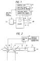
- the air-fuel ratio control apparatus (see Fig. 1) comprises an oxygen sensor 14 provided in an exhaust outlet 12 of an engine 11 and for detecting an oxygen concentration in exhaust gas, and a control unit 15 for correcting and controlling the air-fuel ratio of the engine 11 depending on the oxygen concentration in the exhaust gas detected by the oxygen sensor 14.
- the control unit 15 comprises an electrode plug 18 for detecting a flame resistance in a combustion chamber of the engine 11.
- the control unit 15 further comprises air-fuel ratio calculation means 6 for calculating an air fuel ratio from a minimum value of the flame resistance detected by the electrode plug 18, and air-fuel ratio correction means 7 for correcting the air-fuel ratio detected by the oxygen sensor 14, using the air-fuel ratio calculated by the air-fuel ratio calculation means 6.
- the control unit 15 corrects and controls the air-fuel ratio of the engine 11 based on the air-fuel ratio corrected by the air-fuel ratio correction means 7.
- the air-fuel ratio calculation means calculates a reference air-fuel ratio from the minimum value of the flame resistance detected by the electrode plug.
- the reference air-fuel ratio calculated by the air-fuel ratio calculation means and the air-fuel ratio detected by the oxygen sensor are compared with each other by the air-fuel ratio correction means. In accordance with the difference between them, the air-fuel ratio detected by the oxygen sensor is corrected. Then, the control unit controls the air-fuel ratio of the engine based on the air-fuel ratio corrected by the air-fuel ratio correction means.
- the reference air-fuel ratio obtained from a flame resistance is not substantially influenced by aged deterioration of the control apparatus. Therefore, even if the oxygen sensor is used for a long period and the air-fuel ratio detected by the oxygen sensor is changed, the air-fuel ratio detected by the oxygen sensor can be corrected based on the reference air-fuel ratio measured by the electrode plug, thereby properly controlling the air-fuel ratio of the engine.
- Figs. 2 to 8 show an embodiment of the invention.
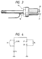
- Fig. 2 is a schematic diagram showing the structure of the air-fuel ratio control apparatus.
- a ternary catalyst 13 for purifying exhaust gas is disposed in an exhaust outlet 12.
- an oxygen sensor 14 for detecting the oxygen concentration in the exhaust gas is attached to a control unit 15.
- the control unit 15 electrically controls a fuel injection valve 16 mounted on an intake path of the engine 11, using a microcomputer. More specifically, the control unit 15 controls an injection amount of a fuel, based on an air-fuel ratio detected by the oxygen sensor 14 and vehicle running conditions (speed, throttle opening degree, engine speed, crank angle, water temperature, brake signal, air flow meter, etc.).
- the oxygen sensor 14 has a known structure in which the electrical output is changed depending on the oxygen concentration in the exhaust gas flowing through the exhaust outlet 12.
- the structure and material of the oxygen sensor are not restricted.
- a known wide range oxygen sensor (universal exhaust gas oxygen sensor) is used which detects an oxygen concentration in a wide range extending from the richer side to the leaner side with respect to the theoretical air-fuel ratio as the center.
- the air-fuel ratio detected by the oxygen sensor 14 is corrected using an output of an electrode plug 18 which detects the flame resistance in a combustion chamber 17 of the engine 11.
- the electrode plug 18 used in this embodiment is united with a spark plug 19 to form one body so as to measure the flame resistance between an outer electrode 20 of the spark plug 19 and a voltage applying electrode 21 of the electrode plug 18.
- Fig. 5 shows a relationship between the minimum value of the flame resistance Ri and the air-fuel ratio. As shown in Fig. 5, even if the explosion is performed constantly in the combustion chamber 17, the minimum value of the flame resistance Ri varies depending on the mixing condition of the fuel or other conditions (see arrows in Fig. 5). By calculating the average value, however, the flame resistance Ri can be plotted as a curve A corresponding to the actual air-fuel ratio.
- the air-fuel ratio is obtained from the average value of the minimum values of the flame resistance Ri of each combustion cycle and the curve shown in Fig. 5 (herein, the obtained air-fuel ratio is referred to as "reference air-fuel ratio"), and the reference air-fuel ratio is compared with the air-fuel ratio detected by the oxygen sensor 14 to obtain a difference. From the difference, a correction value for correcting the air-fuel ratio detected by the oxygen sensor 14 is calculated.
- Step S2 Thereafter, it is judged whether or not a prescribed number of data have been stored. That is, for example, it is judged whether or not the minimum values of the flame resistance Ri for several tens explosion strokes or more have been stored (step S3). If the judgment is NO, it is judged whether the running conditions of the engine 11 suitable for the air-fuel ratio checking on the basis of the flame resistance Ri remain to continue or not (step S4). If the judgment is YES, the process returns to step S2. If the judgment in step S4 is NO, the stored data of the minimum values of the flame resistance Ri are reset (step S5) and the process is returned.
- step S3 If the judgment in step S3 is YES, the stored minimum values of the flame resistance Ri for the prescribed number of explosion strokes are averaged, and a reference air-fuel ratio is calculated from the averaged value and data corresponding to the graph A shown in Fig. 5 and stored in a ROM (not shown) of the control unit 15 (step S6). Then, the reference air-fuel ratio calculated in step S6, and the air-fuel ratio detected by the oxygen sensor 14 (if desired, this may be also averaged) are compared with each other. From this difference, a correction coefficient ⁇ for correcting the air-fuel ratio detected by the oxygen sensor 14 is obtained (alternatively, a correction coefficient for the lean side, and a correction coefficient for the rich side may be separately obtained) (step S7). The calculated correction coefficient ⁇ is stored in the not-shown RAM of the control unit 15 (step S8), and then the process is returned.
- the control for correcting the air-fuel ratio detected by the oxygen sensor 14 using the above correction coefficient ⁇ , and the control of the air-fuel ratio of the engine 11 using the corrected air-fuel ratio are performed independently of the above-described control.
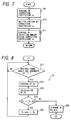
- An example of the controls will be briefly described with reference to a flowchart shown in Fig. 7.
- step S9 When the engine 11 is started (START), the correction coefficient ⁇ stored in the control unit 15 is firstly read out (step S9). Then, the air-fuel ratio detected by the oxygen sensor 14 is multiplied by the correction coefficient ⁇ (step S10). Using the vehicle running conditions and the corrected air-fuel ratio, the fuel injection valve 16 is controlled by a known control technique (step S11).
- the air-fuel ratio calculation means of the present invention for calculating the reference air-fuel ratio from the minimum value of the flame resistance is implemented by steps S1 to S6 mentioned above.
- the air-fuel ratio correction means for correcting the air-fuel ratio detected by the oxygen sensor using the reference air-fuel ratio is implemented by steps S7 to S10 mentioned above.
- step S1 in which it is judged whether or not the running conditions of the engine are stable, will be described in more detail.
- the minimum value of the flame resistance [Ri]min is dominantly affected by the air-fuel ratio, it is also affected by swirl (number of rotation), fill factor of charging (load), ignition timing advance and the like through the influence of the flame temperature (see collection of papers of Mechanical Society vol. 33, No. 252, Page 1278-1287). Accordingly, when the minimum value of the flame resistance [Ri]min is measured, it is necessary to take a step in which it is confirmed in advance whether or not the running conditions meet predetermined conditions. Of course, the step may be judged as yes if any one of a plurality of predetermined conditions as described above (running conditions) is met.
- the curve of [Ri]min versus air-fuel ratio (A/F) as shown in Fig. 5 under the respective conditions may be obtained in advance by a bench test, or it may be obtained through learning during usage of the engine mounted with an A/F sensor while the sensor is new and does not deteriorate.
- step S2 will be described in more detail with reference to the flow chart shown in Fig. 8.
- the flame resistance is measured for every crank angle of 1°.
- step S21 it is judged whether or not the crank angle measured by a crank angle sensor has advanced by 1°. If the judgement is NO, the process is returned to step S21. If the judgement in step S21 is YES, the voltage Vr appearing across the series resistor 22 is read (step S22), and the flame resistance Ri is calculated from the equation (I) described before (step S23). Next, it is judged whether or not the flame resistance Ri calculated this time is smaller than Ri min (step S24). Since Ri min is cleared up at the initial stage of one cycle of combustion, the read value at the first time is smaller than Ri min.
- step S24 If the judgement in step S24 is YES, the flame resistance Ri calculated this time is made Ri min (step S25). That is, when the flame resistance Ri is lowering, Ri min is sequentially changed to smaller value. If the judgement in step S24 is NO, that is, when the flame resistance begins to rise, the value of Ri min at the previous time is stored as the minimum value of the flame resistance Ri in this cycle (step S26).
- the reference air-fuel ratio obtained from a flame resistance is not influenced by aged deterioration.
- the correction coefficient is updated using the reference air-fuel ratio which is not influenced by aged deterioration, every time when any one of the predetermined running conditions of the engine 11 is met and become stable. Therefore, even if the oxygen sensor 14 is used for a long period and the air-fuel ratio detected by the oxygen sensor is changed, an accurate air-fuel ratio can always be available from the updated correction coefficient and the output detected by the oxygen sensor 14.
- the air-fuel ratio control apparatus of the embodiment can properly control the air-fuel ratio of the engine 11 based on an accurate air-fuel ratio, even when the oxygen sensor 14 is used for a long period.
- the structure having only a single oxygen sensor 14 can cope with the aged deterioration of the sensor. Therefore, as compared with the prior art technique in which two oxygen sensors are used for coping with the aged deterioration, the production cost of the air-fuel ratio control apparatus can be reduced.
- the flame resistance value is calculated for every advance of 1° of the crank angle so as to obtain the minimum value.
- the flame resistance value may be always calculated.
- the minimum value of the flame resistance is analogically calculated using a well-known circuit as "peak-held circuit". In that circuit, a capacitor is charged through a diode by a charging voltage proportional to the instant flame-resistance. In this way, the minimum value of the flame resistance can be obtained by any other appropriate technique.
- the wide range oxygen sensor (UEGO sensor) is used as the oxygen sensor.
- UEGO sensor wide range oxygen sensor
- any other types of oxygen sensors including a ⁇ point sensor which detects the air-fuel ratio in the vicinity of the theoretical air-fuel ratio by the rapid change in its output, can be used.
- control apparatus may be constructed so that, when the difference between the air-fuel ratio detected by the oxygen sensor and the reference air-fuel ratio measured by the electrode plug reaches a prescribed value, the user is informed that the oxygen sensor is required to be exchanged.
- the electrode plug and the spark plug are formed into one unit, but alternatively, they can be separately provided in the combustion chamber.
- the flame resistance may be measured using a spark discharge gap of the spark plug.
- the reference air-fuel ratio is once calculated from the minimum value of the flame resistance. Since the minimum value of the flame resistance corresponds to the reference air-fuel ratio, the air-fuel ratio detected by the oxygen sensor may be corrected using the minimum value of the flame resistance.
- the present invention can be applied to a control apparatus for a multi-cylindered engine.
- the flame resistance value may be measured for each cylinder, or the flame resistance value for a representative one or some of the cylinders may be measured.
- ( ⁇ M )0 is given by, for example, equation (5), and k3 are determined in advance by a bench test within a required range.
- (Ri min3)0 is obtained and stored through learning under an initial state of the sensor which has not been deteriorated.
- (Ri min3)0' is obtained every time from the output of an electrode plug by a digital calculation or analogic method so that ( ⁇ M )0', that is, the reference value of ⁇ M as an actual value of ⁇ M can be obtained.
- the difference between ( ⁇ M )0' and ( ⁇ M )0' is an output error according to deterioration of the sensor, which is used as the correction value for the sensor output. Also, it may be designed that when the difference becomes a predetermined value, it is judged that the sensor should be replaced.
- the output value ( ⁇ MS )0' of the sensor can be euqal to the value of ( ⁇ M )0 if the feedback control has been conducted by using directly the raw output value ( ⁇ MS )0', and ( ⁇ MS )0' can be calcaulated by using the value of ( ⁇ M )0 and a correction value ⁇ MS for the raw output value ( ⁇ MS )0 ' if any feedback control has been conducted by using that corrected value [( ⁇ MS )0' + ⁇ MS ] of the raw output value ( ⁇ MS )0' which has been corrected by the correction value ⁇ MS above.
Landscapes
- Engineering & Computer Science (AREA)
- Chemical & Material Sciences (AREA)
- Combustion & Propulsion (AREA)
- Mechanical Engineering (AREA)
- General Engineering & Computer Science (AREA)
- Analytical Chemistry (AREA)
- Electrical Control Of Air Or Fuel Supplied To Internal-Combustion Engine (AREA)
- Combined Controls Of Internal Combustion Engines (AREA)
Priority Applications (1)
| Application Number | Priority Date | Filing Date | Title |
|---|---|---|---|
| EP95104728A EP0671555A1 (de) | 1992-02-13 | 1993-02-10 | Verfahren zum Erfassen der Verschlechterung eines Luft-Kraftstoff-Verhältnis-Sensors |
Applications Claiming Priority (2)
| Application Number | Priority Date | Filing Date | Title |
|---|---|---|---|
| JP26947/92 | 1992-02-13 | ||
| JP2694792 | 1992-02-13 |
Related Child Applications (1)
| Application Number | Title | Priority Date | Filing Date |
|---|---|---|---|
| EP95104728.1 Division-Into | 1993-02-10 |
Publications (2)
| Publication Number | Publication Date |
|---|---|
| EP0555831A1 true EP0555831A1 (de) | 1993-08-18 |
| EP0555831B1 EP0555831B1 (de) | 1996-05-08 |
Family
ID=12207354
Family Applications (2)
| Application Number | Title | Priority Date | Filing Date |
|---|---|---|---|
| EP93102067A Expired - Lifetime EP0555831B1 (de) | 1992-02-13 | 1993-02-10 | Luft-Kraftstoff-Verhältnis-Regeleinrichtung und -Verfahren |
| EP95104728A Withdrawn EP0671555A1 (de) | 1992-02-13 | 1993-02-10 | Verfahren zum Erfassen der Verschlechterung eines Luft-Kraftstoff-Verhältnis-Sensors |
Family Applications After (1)
| Application Number | Title | Priority Date | Filing Date |
|---|---|---|---|
| EP95104728A Withdrawn EP0671555A1 (de) | 1992-02-13 | 1993-02-10 | Verfahren zum Erfassen der Verschlechterung eines Luft-Kraftstoff-Verhältnis-Sensors |
Country Status (2)
| Country | Link |
|---|---|
| US (1) | US5247910A (de) |
| EP (2) | EP0555831B1 (de) |
Cited By (2)
| Publication number | Priority date | Publication date | Assignee | Title |
|---|---|---|---|---|
| WO1999050548A1 (de) * | 1998-03-27 | 1999-10-07 | Bayerische Motoren Werke Aktiengesellschaft | Vorrichtung zur messung des ionenstroms im zylinder einer brennkraftmaschine |
| GB2453014A (en) * | 2007-07-13 | 2009-03-25 | Ford Global Tech Llc | Monitoring of exhaust gas oxygen sensor performance |
Families Citing this family (21)
| Publication number | Priority date | Publication date | Assignee | Title |
|---|---|---|---|---|
| DE4139561A1 (de) * | 1991-11-30 | 1993-06-03 | Bosch Gmbh Robert | Verfahren und vorrichtung zum ueberwachen des alterungszustandes einer sauerstoffsonde |
| DE4402938A1 (de) * | 1994-02-01 | 1995-08-03 | Fev Motorentech Gmbh & Co Kg | Verfahren zur Steuerung eines Kolbenverbrennungsmotors unter Einhaltung der Laufgrenze |
| DE19743060A1 (de) * | 1997-09-30 | 1999-04-01 | Bosch Gmbh Robert | Verfahren zum Betrieb einer Brennkraftmaschine und Kraftstoffeinspritzsystem zur Durchführung des Verfahrens |
| DE102004010344A1 (de) * | 2003-03-04 | 2004-10-14 | Denso Corp., Kariya | Sekundärluftzufuhrsteuerungsvorrichtung für eine Brennkraftmaschine |
| US7628137B1 (en) | 2008-01-07 | 2009-12-08 | Mcalister Roy E | Multifuel storage, metering and ignition system |
| US8074625B2 (en) | 2008-01-07 | 2011-12-13 | Mcalister Technologies, Llc | Fuel injector actuator assemblies and associated methods of use and manufacture |
| US8387599B2 (en) | 2008-01-07 | 2013-03-05 | Mcalister Technologies, Llc | Methods and systems for reducing the formation of oxides of nitrogen during combustion in engines |
| US8635985B2 (en) | 2008-01-07 | 2014-01-28 | Mcalister Technologies, Llc | Integrated fuel injectors and igniters and associated methods of use and manufacture |
| CA2772044C (en) | 2009-08-27 | 2013-04-16 | Mcalister Technologies, Llc | Shaping a fuel charge in a combustion chamber with multiple drivers and/or ionization control |
| KR101364416B1 (ko) | 2009-12-07 | 2014-02-17 | 맥알리스터 테크놀로지즈 엘엘씨 | 대형 엔진 적용에 적합한 일체식 연료 인젝터 점화기 및 연관된 이용 및 제조방법 |
| KR20120086375A (ko) * | 2009-12-07 | 2012-08-02 | 맥알리스터 테크놀로지즈 엘엘씨 | 연료 인젝터 및 점화기를 위한 적응 제어 시스템 |
| EP2534347B1 (de) | 2010-02-13 | 2016-05-04 | McAlister, Roy Edward | Verfahren und systeme zur adaptiven kühlung von verbrennungskammern in motoren |
| US20110297753A1 (en) | 2010-12-06 | 2011-12-08 | Mcalister Roy E | Integrated fuel injector igniters configured to inject multiple fuels and/or coolants and associated methods of use and manufacture |
| US8521400B2 (en) * | 2010-06-22 | 2013-08-27 | Purpose Company Limited | Combustion apparatus and method for combustion control |
| US8919377B2 (en) | 2011-08-12 | 2014-12-30 | Mcalister Technologies, Llc | Acoustically actuated flow valve assembly including a plurality of reed valves |
| US8746197B2 (en) | 2012-11-02 | 2014-06-10 | Mcalister Technologies, Llc | Fuel injection systems with enhanced corona burst |
| US9169814B2 (en) | 2012-11-02 | 2015-10-27 | Mcalister Technologies, Llc | Systems, methods, and devices with enhanced lorentz thrust |
| US9169821B2 (en) | 2012-11-02 | 2015-10-27 | Mcalister Technologies, Llc | Fuel injection systems with enhanced corona burst |
| US9115325B2 (en) | 2012-11-12 | 2015-08-25 | Mcalister Technologies, Llc | Systems and methods for utilizing alcohol fuels |
| US9200561B2 (en) | 2012-11-12 | 2015-12-01 | Mcalister Technologies, Llc | Chemical fuel conditioning and activation |
| US9194337B2 (en) | 2013-03-14 | 2015-11-24 | Advanced Green Innovations, LLC | High pressure direct injected gaseous fuel system and retrofit kit incorporating the same |
Citations (2)
| Publication number | Priority date | Publication date | Assignee | Title |
|---|---|---|---|---|
| US4519366A (en) * | 1982-03-24 | 1985-05-28 | May Michael G | Method and apparatus for controlling the composition of the combustion charge in internal combustion engines |
| US5058552A (en) * | 1988-06-08 | 1991-10-22 | Mitsubishi Denki K.K. | Engine control apparatus |
Family Cites Families (7)
| Publication number | Priority date | Publication date | Assignee | Title |
|---|---|---|---|---|
| JPS5319887A (en) * | 1976-08-08 | 1978-02-23 | Nippon Soken | Deterioration detecting apparatus for oxygen concentration detector |
| JPS5486025A (en) * | 1977-12-21 | 1979-07-09 | Nissan Motor Co Ltd | Air fuel ratio controller |
| JPS59224436A (ja) * | 1983-06-03 | 1984-12-17 | Nippon Carbureter Co Ltd | エンジンの空燃比制御方法 |
| JPS6131640A (ja) * | 1984-07-23 | 1986-02-14 | Nippon Soken Inc | 空燃比制御装置 |
| US4930478A (en) * | 1988-05-13 | 1990-06-05 | Barrack Technology Limited | Method of operating an engine |
| JPH07119742B2 (ja) * | 1988-06-30 | 1995-12-20 | 本田技研工業株式会社 | 酸素濃度検出装置の劣化判定方法 |
| JPH0326844A (ja) * | 1989-06-21 | 1991-02-05 | Japan Electron Control Syst Co Ltd | 内燃機関の燃料供給制御装置における空燃比フィードバック補正装置 |
-
1993
- 1993-02-09 US US08/015,534 patent/US5247910A/en not_active Expired - Lifetime
- 1993-02-10 EP EP93102067A patent/EP0555831B1/de not_active Expired - Lifetime
- 1993-02-10 EP EP95104728A patent/EP0671555A1/de not_active Withdrawn
Patent Citations (2)
| Publication number | Priority date | Publication date | Assignee | Title |
|---|---|---|---|---|
| US4519366A (en) * | 1982-03-24 | 1985-05-28 | May Michael G | Method and apparatus for controlling the composition of the combustion charge in internal combustion engines |
| US5058552A (en) * | 1988-06-08 | 1991-10-22 | Mitsubishi Denki K.K. | Engine control apparatus |
Cited By (3)
| Publication number | Priority date | Publication date | Assignee | Title |
|---|---|---|---|---|
| WO1999050548A1 (de) * | 1998-03-27 | 1999-10-07 | Bayerische Motoren Werke Aktiengesellschaft | Vorrichtung zur messung des ionenstroms im zylinder einer brennkraftmaschine |
| GB2453014A (en) * | 2007-07-13 | 2009-03-25 | Ford Global Tech Llc | Monitoring of exhaust gas oxygen sensor performance |
| US7861515B2 (en) | 2007-07-13 | 2011-01-04 | Ford Global Technologies, Llc | Monitoring of exhaust gas oxygen sensor performance |
Also Published As
| Publication number | Publication date |
|---|---|
| US5247910A (en) | 1993-09-28 |
| EP0555831B1 (de) | 1996-05-08 |
| EP0671555A1 (de) | 1995-09-13 |
Similar Documents
| Publication | Publication Date | Title |
|---|---|---|
| US5247910A (en) | Air-fuel ratio control apparatus | |
| US7248960B2 (en) | Air-fuel ratio sensor monitor, air-fuel ratio detector, and air-fuel ratio control | |
| US5533332A (en) | Method and apparatus for self diagnosis of an internal combustion engine | |
| US5325664A (en) | System for determining deterioration of catalysts of internal combustion engines | |
| JP3074975B2 (ja) | 内燃機関の触媒劣化判定装置 | |
| US4982331A (en) | Fuel injector control apparatus | |
| US4989570A (en) | Fail detecting system for sensor monitoring concentration of a fuel in blended multi-fuel for internal combustion engine and fail-safe system in lambda-control | |
| US4887576A (en) | Method of determining acceptability of an exhaust concentration sensor | |
| US4777922A (en) | Method of abnormality detection of oxygen concentration sensor | |
| US5212947A (en) | Failure-detecting device for air-fuel ratio sensors of internal combustion engines | |
| US5014670A (en) | Spark ignition timing control system for internal combustion engine | |
| JPS6340268B2 (de) | ||
| US4889098A (en) | Air-fuel ratio detecting apparatus for an internal combustion engine equipped with a heater controller | |
| EP1471221B1 (de) | Feststellungsvorrichtung der Katalysatorverschlechterung einer Brennkraftmaschine | |
| US20050072410A1 (en) | Air-fuel ratio feedback control apparatus and method for internal combustion engine | |
| US5951618A (en) | Detector device for combustion state in internal combustion engine | |
| JPH065047B2 (ja) | 空燃比制御装置 | |
| US4944274A (en) | Air-fuel ratio control apparatus for internal combustion engines | |
| US5537978A (en) | Apparatus and method for determining characteristic of fuel supplied to vehicular internal combustion engine | |
| JPH0323735B2 (de) | ||
| JP3525545B2 (ja) | 空燃比センサの異常診断装置 | |
| US5834624A (en) | Air-fuel ratio detecting device and method therefor | |
| US4909223A (en) | Air-fuel ratio control apparatus for multicylinder engine | |
| JP4460077B2 (ja) | 内燃機関の制御方法および装置 | |
| JPH06229969A (ja) | 空燃比制御装置および酸素センサの劣化検出装置 |
Legal Events
| Date | Code | Title | Description |
|---|---|---|---|
| PUAI | Public reference made under article 153(3) epc to a published international application that has entered the european phase |
Free format text: ORIGINAL CODE: 0009012 |
|
| AK | Designated contracting states |
Kind code of ref document: A1 Designated state(s): DE FR GB IT NL |
|
| 17P | Request for examination filed |
Effective date: 19931124 |
|
| 17Q | First examination report despatched |
Effective date: 19941121 |
|
| RBV | Designated contracting states (corrected) | ||
| REG | Reference to a national code |
Ref country code: DE Ref legal event code: 8566 |
|
| GRAA | (expected) grant |
Free format text: ORIGINAL CODE: 0009210 |
|
| AK | Designated contracting states |
Kind code of ref document: B1 Designated state(s): GB |
|
| XX | Miscellaneous (additional remarks) |
Free format text: TEILANMELDUNG 95104728.1 EINGEREICHT AM 10/02/93. |
|
| XX | Miscellaneous (additional remarks) | ||
| PLBE | No opposition filed within time limit |
Free format text: ORIGINAL CODE: 0009261 |
|
| STAA | Information on the status of an ep patent application or granted ep patent |
Free format text: STATUS: NO OPPOSITION FILED WITHIN TIME LIMIT |
|
| 26N | No opposition filed | ||
| PGFP | Annual fee paid to national office [announced via postgrant information from national office to epo] |
Ref country code: GB Payment date: 19990211 Year of fee payment: 7 |
|
| PG25 | Lapsed in a contracting state [announced via postgrant information from national office to epo] |
Ref country code: GB Free format text: LAPSE BECAUSE OF NON-PAYMENT OF DUE FEES Effective date: 20000210 |
|
| GBPC | Gb: european patent ceased through non-payment of renewal fee |
Effective date: 20000210 |