EP0555839A2 - Gerät zum Speichern und Abgeben von pigmentierten Markierungsteilchen - Google Patents
Gerät zum Speichern und Abgeben von pigmentierten Markierungsteilchen Download PDFInfo
- Publication number
- EP0555839A2 EP0555839A2 EP93102097A EP93102097A EP0555839A2 EP 0555839 A2 EP0555839 A2 EP 0555839A2 EP 93102097 A EP93102097 A EP 93102097A EP 93102097 A EP93102097 A EP 93102097A EP 0555839 A2 EP0555839 A2 EP 0555839A2
- Authority
- EP
- European Patent Office
- Prior art keywords
- cartridge
- housing
- flexible sheet
- storing
- sheet member
- Prior art date
- Legal status (The legal status is an assumption and is not a legal conclusion. Google has not performed a legal analysis and makes no representation as to the accuracy of the status listed.)
- Granted
Links
- 239000002245 particle Substances 0.000 title claims abstract description 59
- 238000011109 contamination Methods 0.000 claims abstract description 16
- 238000007789 sealing Methods 0.000 claims abstract description 7
- 238000004804 winding Methods 0.000 claims description 16
- 230000000295 complement effect Effects 0.000 claims 1
- 230000033458 reproduction Effects 0.000 description 11
- 238000003780 insertion Methods 0.000 description 4
- 230000037431 insertion Effects 0.000 description 4
- 239000013618 particulate matter Substances 0.000 description 3
- 238000000034 method Methods 0.000 description 2
- 239000000853 adhesive Substances 0.000 description 1
- 238000004026 adhesive bonding Methods 0.000 description 1
- 230000001070 adhesive effect Effects 0.000 description 1
- POIUWJQBRNEFGX-XAMSXPGMSA-N cathelicidin Chemical compound C([C@@H](C(=O)N[C@@H](CCCNC(N)=N)C(=O)N[C@@H](CCCCN)C(=O)N[C@@H](CO)C(=O)N[C@@H](CCCCN)C(=O)N[C@@H](CCC(O)=O)C(=O)N[C@@H](CCCCN)C(=O)N[C@@H]([C@@H](C)CC)C(=O)NCC(=O)N[C@@H](CCCCN)C(=O)N[C@@H](CCC(O)=O)C(=O)N[C@@H](CC=1C=CC=CC=1)C(=O)N[C@@H](CCCCN)C(=O)N[C@@H](CCCNC(N)=N)C(=O)N[C@@H]([C@@H](C)CC)C(=O)N[C@@H](C(C)C)C(=O)N[C@@H](CCC(N)=O)C(=O)N[C@@H](CCCNC(N)=N)C(=O)N[C@@H]([C@@H](C)CC)C(=O)N[C@@H](CCCCN)C(=O)N[C@@H](CC(O)=O)C(=O)N[C@@H](CC=1C=CC=CC=1)C(=O)N[C@@H](CC(C)C)C(=O)N[C@@H](CCCNC(N)=N)C(=O)N[C@@H](CC(N)=O)C(=O)N[C@@H](CC(C)C)C(=O)N[C@@H](C(C)C)C(=O)N1[C@@H](CCC1)C(=O)N[C@@H](CCCNC(N)=N)C(=O)N[C@@H]([C@@H](C)O)C(=O)N[C@@H](CCC(O)=O)C(=O)N[C@@H](CO)C(O)=O)NC(=O)[C@H](CC=1C=CC=CC=1)NC(=O)[C@H](CC(O)=O)NC(=O)CNC(=O)[C@H](CC(C)C)NC(=O)[C@@H](N)CC(C)C)C1=CC=CC=C1 POIUWJQBRNEFGX-XAMSXPGMSA-N 0.000 description 1
- 230000008878 coupling Effects 0.000 description 1
- 238000010168 coupling process Methods 0.000 description 1
- 238000005859 coupling reaction Methods 0.000 description 1
- 239000000463 material Substances 0.000 description 1
- 238000012986 modification Methods 0.000 description 1
- 230000004048 modification Effects 0.000 description 1
- 230000002028 premature Effects 0.000 description 1
- 230000000750 progressive effect Effects 0.000 description 1
Images



Classifications
-
- G—PHYSICS
- G03—PHOTOGRAPHY; CINEMATOGRAPHY; ANALOGOUS TECHNIQUES USING WAVES OTHER THAN OPTICAL WAVES; ELECTROGRAPHY; HOLOGRAPHY
- G03G—ELECTROGRAPHY; ELECTROPHOTOGRAPHY; MAGNETOGRAPHY
- G03G15/00—Apparatus for electrographic processes using a charge pattern
- G03G15/06—Apparatus for electrographic processes using a charge pattern for developing
- G03G15/08—Apparatus for electrographic processes using a charge pattern for developing using a solid developer, e.g. powder developer
- G03G15/0822—Arrangements for preparing, mixing, supplying or dispensing developer
- G03G15/0865—Arrangements for supplying new developer
- G03G15/0867—Arrangements for supplying new developer cylindrical developer cartridges, e.g. toner bottles for the developer replenishing opening
- G03G15/087—Developer cartridges having a longitudinal rotational axis, around which at least one part is rotated when mounting or using the cartridge
- G03G15/0872—Developer cartridges having a longitudinal rotational axis, around which at least one part is rotated when mounting or using the cartridge the developer cartridges being generally horizontally mounted parallel to its longitudinal rotational axis
-
- G—PHYSICS
- G03—PHOTOGRAPHY; CINEMATOGRAPHY; ANALOGOUS TECHNIQUES USING WAVES OTHER THAN OPTICAL WAVES; ELECTROGRAPHY; HOLOGRAPHY
- G03G—ELECTROGRAPHY; ELECTROPHOTOGRAPHY; MAGNETOGRAPHY
- G03G15/00—Apparatus for electrographic processes using a charge pattern
- G03G15/06—Apparatus for electrographic processes using a charge pattern for developing
- G03G15/08—Apparatus for electrographic processes using a charge pattern for developing using a solid developer, e.g. powder developer
- G03G15/0822—Arrangements for preparing, mixing, supplying or dispensing developer
- G03G15/0877—Arrangements for metering and dispensing developer from a developer cartridge into the development unit
- G03G15/0881—Sealing of developer cartridges
- G03G15/0884—Sealing of developer cartridges by a sealing film to be ruptured or cut
-
- Y—GENERAL TAGGING OF NEW TECHNOLOGICAL DEVELOPMENTS; GENERAL TAGGING OF CROSS-SECTIONAL TECHNOLOGIES SPANNING OVER SEVERAL SECTIONS OF THE IPC; TECHNICAL SUBJECTS COVERED BY FORMER USPC CROSS-REFERENCE ART COLLECTIONS [XRACs] AND DIGESTS
- Y10—TECHNICAL SUBJECTS COVERED BY FORMER USPC
- Y10S—TECHNICAL SUBJECTS COVERED BY FORMER USPC CROSS-REFERENCE ART COLLECTIONS [XRACs] AND DIGESTS
- Y10S222/00—Dispensing
- Y10S222/01—Xerography
Definitions
- the present invention relates in general to apparatus for storing and dispensing particulate matter, and more particularly to a apparatus for storing and dispensing pigmented marking particles for a reproduction apparatus.
- a uniformly charged photoconductive member is exposed to a light image of information to be reproduced. Such exposure of the photoconductive member alters the uniform charge in an image-wise pattern forming a latent image charge pattern thereon.
- the charge pattern is then developed with pigmented marking particles from a development mechanism.
- the developed image is thereafter transferred to a receiver member and fixed to the receiver member to form the desired reproduction.
- the pigmented marking particles in the development mechanism are depleted and must be replenished.
- reproduction apparatus commonly have dispensers which periodically dump marking particles into the development mechanism. After some period of time, it is necessary to replenish the marking particles within the dispenser. Adding marking particles to the dispenser takes considerable care, since any spillage results in contamination, both to the immediate environment and to the surrounding area since the marking particles may easily become airborne. Further, the marking particles cling to the operator and his/her clothing, making replenishment a messy procedure.
- FIG. 477 An example of a marking particle replenishment package is shown in USA 4,732,277.
- Such replenishment package is in the form of an elongated cartridge defining a chamber for storing marking particles.
- a flexible sealing sleeve is removably secured to the cartridge to seal an elongated opening therein.
- the sleeve adhered to the cartridge by adhesive material, has a pull strip positioned within and along the length of the sleeve. When the strip is pulled, the sleeve is peeled from the opening turning itself inside out.
- the cartridge is inserted into the reproduction apparatus with the sealing sleeve in place, and then the sleeve is removed. While this considerably reduces the potential for contamination, the sleeve itself may have marking particles adhering thereto which can cause contamination when the sleeve is removed.
- FIG. 5 Another marking particle package is shown in USA 5,030,998.
- a seal member for a cartridge is attachable to a winding mechanism.
- the seal member is wound up by the winding mechanism whereby the cartridge is opened to enable the marking particles to be dispensed.
- the area of the seal member in contact with the marking particles is exposed such that airborne particles are free to escape and contaminate the environment.
- This invention is directed to an apparatus for storing and dispensing pigmented marking particles for a development mechanism of a reproduction apparatus in which contamination is substantially prevented.
- the storing and dispensing apparatus comprises a cartridge including a housing for storing pigmented marking particles, and an elongated opening in the housing through which such marking particles may be dispensed.
- a cover is removably secured to the cartridge housing to seal the housing opening to prevent contamination of the environment by escape of such marking particles through the opening.
- the cover in the preferred embodiment being a flexible sheet member, is selectively removed from sealing relation with the cartridge housing opening and held adjacent to the cartridge away from exposure to the environment when the cartridge is located relative to the development mechanism, whereby marking particles may readily be dispensed into the development mechanism through the housing opening and contamination of the environment is substantially prevented.
- Fig. 1 shows an apparatus, designated generally by the numeral 10, for storing and dispensing particulate matter according to this invention.
- the particulate matter is, for example, pigmented marking particles which may be used in a development mechanism 12 of a typical reproduction apparatus.
- the pigmented marking particles in the development mechanism 12 serve to develop a latent image charge pattern on a dielectric member (shown in phantom as web W in Fig. 1) to form a visible, transferrable image thereon.
- the pigmented marking particles in the development mechanism 12 are depleted.
- the storing and dispensing apparatus 10 serves, in the manner to be fully described hereinbelow, to enable the supply of pigmented marking particles in the development mechanism 12 to be replenished without contamination of the environment as was common with prior storing and dispensing apparatus.
- the storing and dispensing apparatus 10 includes a cartridge 14.
- the cartridge 14 is constructed of a tubular housing 16 closed at each end by caps 18, 20 to form a storage chamber for pigmented marking particles therein.
- the housing 16 has an elongated slot 16a defined through a wall thereof.
- the slot 16a provides an opening which enables the housing chamber to be initially loaded with pigmented marking particles, and at a desired time, to have the particles dispensed therefrom.
- a handle 22 is attached to the end cap 18 to facilitate handling of the cartridge 14.
- a removable cover 24 is provided for the slot 16a of the cartridge housing 16.
- the cover 24 includes a flexible sheet member 26 of a size substantially larger than the slot 16a.
- a substantially rigid rod 28 is attached, in any well known manner, to a longitudinal marginal edge 26a of the flexible sheet member 26.
- the development mechanism 12 has, attached thereto, a receiver 30 for the cartridge 14.
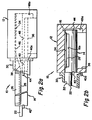
- the receiver 30 includes an orientation funnel 32 communicating with an internal chamber 34 (see Figs. 2a, 2b).
- the internal chamber 34 defines an opening 36 through which pigmented marking particles are dispensed into a suitable feeder (not shown) where the particles are fed in any well known manner to an applicator A to develop a latent image charge pattern on the dielectric member web W.
- the orientation funnel 32 further includes a first slot 38 and a second slot 40.
- the first slot 38 is configured to receive rod 28 in a manner which accommodates for breaking of the seal of the flexible sheet member 26 to the cartridge housing 16 in a manner to fully explained below.
- the rod 28 (and the accommodating slot 38) could be configured in any other suitable shape such as flat shim stock for example.
- the second slot 40 is configured to receive tabs 42 and 44, attached to the cartridge housing 16, to guide the cartridge 14 into the internal chamber 34 of the development mechanism 12 in proper orientation.
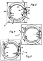
- the cartridge is manually oriented such that tab 44 on the cartridge housing 16 is aligned with the slot 40 of the orientation funnel 32. In such orientation, the rod 28 is aligned with slot 38 (see Figs. 2a, 3, 6a).
- the cartridge 14 is then manually inserted into the funnel.
- the slot 38 is configured to lift the rod 28 as it progressively enters the slot, and move the rod away from the housing 16 until the flexible sheet member 26 attached thereto is stripped from the cartridge housing 16 (i.e., the seal between the flexible sheet member and the cartridge housing is broken).
- the rod 28 is aligned with a slot 46 in the internal chamber 34 of the development mechanism 12, and the tab 44 is aligned with a slot 48 in such internal chamber.
- the cartridge 14 continues until the tab 42, which extends radially from the housing 16 farther than tab 44, engages the front wall of the development mechanism 12 (see Fig. 2b). Such engagement serves as a locating stop for the cartridge.
- the cartridge 14 is fully inserted into the development mechanism 12, and is properly oriented with respect thereto.
- slots 38 and 46 may have other suitable communicating configurations to accomplish the desired result of breaking the seal between the flexible sheet member 26 and the cartridge housing 16. That is, for example, the slots may comprise a communicating ramp sloping upwardly from the front of the orientation funnel 32 to the rear wall of the internal chamber 34 of the development mechanism 12. Such more gently sloping ramp configuration reduces the forces required to break the seal between the flexible sheet member 26 and the cartridge housing 16.
- tab 44 With the cartridge 14 fully inserted into the development mechanism 12, tab 44 is aligned with an annular slot 48a in the internal chamber, and the tab 42 is aligned with an annular slot 40a in the orientation funnel 32. Tab 44 (and its associated annular slot 48a) is longer in the longitudinal direction than tab 42 (and its associated annular slot 40a). In this manner, on insertion of the cartridge 14 into the development mechanism, tab 44 cannot enter the annular slot 40a and premature rotation of the cartridge is thereby prevented. As a result of the respective tab/slot alignments, the cartridge 14 is free to rotate in the internal chamber 34. The handle 22 for the cartridge 14 is then manually rotated (in a clockwise direction in the drawings).
- the flexible sheet member 26 Since the rod 28 is captured in the slot 46, on rotation of the cartridge, the flexible sheet member 26 is peeled back (see Fig. 4). The manual rotation of the cartridge 14 continues until the cartridge has reached the position shown in Fig. 5 where the tab 42 engages the end wall 40b (stop) of the annular slot 40a (substantially 180 o from the position shown in Fig. 3). At this point, the flexible sheet member 26 completely uncovers the opening 16a in the cartridge housing. Further, the opening 16a overlies the opening 36 in the internal chamber 34 of the development mechanism 12. Accordingly, the pigmented marking particles stored in the cartridge 14 are free to be dispensed into the development mechanism 12. Since the flexible sheet member 26 is spaced from the opening 34, and is shielded by its location between the cartridge housing 16 and the wall of the internal chamber 34, contamination of the flexible sheet member is substantially prevented.
- the cartridge can be removed from the development mechanism, by simply reversing the above described insertion procedure. That is, the handle 22 of the cartridge is manually rotated in the opposite direction (counter-clockwise) substantially 180 o to return the cartridge to the position shown in Fig. 3, from the position shown in Fig. 5. At such position, the tabs 42 and 44 align with the slots 48 (in the internal chamber 34 of the development mechanism 12) and 40 (in the orientation funnel 32). The cartridge 14 can then be readily removed from the internal chamber 34. It is of course clear that, on return rotation of the cartridge 14, the flexible sheet member 26 is returned to its position covering the housing opening 16a. In this manner, when the cartridge is removed from the development mechanism 12, repositioning of the flexible sheet member to cover the opening 16a assures that contamination will further be prevented.
- FIG. 7 an alternate embodiment, designated by the numeral 110, of the arrangement for removing the flexible sheet member 26 as the cover 24 for the housing opening 16a of the cartridge 14 is shown.
- a slot 46' extending the full length (in the longitudinal direction) of the internal chamber.
- a rotatable element 50 having a slot 52 adapted to receive the rod 28 of the cartridge 14 is located in the slot 46'.
- a handle 54 is connected to the element 50 for selectively rotating such element in the slot 46'.
- rotation of the element 50 may be manually induced, or may be effected by coupling any suitable power winding mechanism (not shown) to the handle 54 or directly to the element 50.
- any suitable power winding mechanism not shown
- the housing 16 of the cartridge 14 is rotated in the chamber 34 until the opening 16a overlies the opening 36 of the internal chamber 34.
- the opening 16a when overlying the opening 36, is fully uncovered, and the pigmented marking particles are dispensed from the cartridge 14 therethrough.
- Fig. 9 shows another alternate embodiment, designated by the numeral 210, of the storing and dispensing apparatus 10 according to this invention.
- This embodiment is similar to the embodiments of Figs. 7 and 8 except the rotatable element 50 and the handle 54 thereof is replaced by a handle 56 connected directly to the rod 28. With this arrangement, rotation of the handle 56 causes the rod 28 to rotate, and the flexible sheet 26 is wound up directly about the rod.
- the operation for uncovering the opening 16a of the cartridge housing 16 and rotating the cartridge to the marking particle dispensing position is the same as described immediately above relative to the operation of the embodiment 110 of Figs. 7 and 8.
- the cartridge 14 includes a housing assembly 60 attached to the end of the cartridge extending outwardly from the development mechanism 12 (when the cartridge is positioned within the development mechanism).
- the housing assembly 60 includes a winding shaft 62 rotatably supported within the housing assembly.
- a readily accessible crank 64 is attached to one end of the winding shaft 62.
- the housing assembly 60 has a guide slot 66 located between the cartridge housing 16 and the winding shaft 62.
- the flexible sheet member 26 includes a portion 68 extending from the far marginal edge thereof, directed through the guide slot 66, attached to the winding shaft 62.
- a shield 70 attached to the housing assembly 60, overlies a portion of the path of the flexible sheet member portion 68as it enters the guide slot 66.
- the crank 64 may be rotated (again, manually or by any suitable motive mechanism) to wind up the flexible sheet member 26 on the shaft 62 to uncover the opening 16a of the cartridge housing 16.
- the shield 70 prevents contamination of the environment by airborne marking particles when the flexible sheet member is wound on the winding shaft.
- the cartridge 14 can be rotated as described above to orient the housing opening 16a in alignment with the opening 36 of the internal chamber 34, and the pigmented marking particles within the cartridge can be similarly dispensed into the development mechanism 12.
Landscapes
- Physics & Mathematics (AREA)
- General Physics & Mathematics (AREA)
- Dry Development In Electrophotography (AREA)
- Packages (AREA)
- Electrophotography Configuration And Component (AREA)
- Photographic Developing Apparatuses (AREA)
Applications Claiming Priority (2)
| Application Number | Priority Date | Filing Date | Title |
|---|---|---|---|
| US835882 | 1992-02-14 | ||
| US07/835,882 US5261568A (en) | 1992-02-14 | 1992-02-14 | Apparatus for storing and dispensing pigmented marking particles |
Publications (3)
| Publication Number | Publication Date |
|---|---|
| EP0555839A2 true EP0555839A2 (de) | 1993-08-18 |
| EP0555839A3 EP0555839A3 (de) | 1994-03-30 |
| EP0555839B1 EP0555839B1 (de) | 1998-04-29 |
Family
ID=25270704
Family Applications (1)
| Application Number | Title | Priority Date | Filing Date |
|---|---|---|---|
| EP93102097A Expired - Lifetime EP0555839B1 (de) | 1992-02-14 | 1993-02-11 | Gerät zum Speichern und Abgeben von pigmentierten Markierungsteilchen |
Country Status (4)
| Country | Link |
|---|---|
| US (1) | US5261568A (de) |
| EP (1) | EP0555839B1 (de) |
| JP (1) | JPH05341651A (de) |
| DE (1) | DE69318197T2 (de) |
Families Citing this family (12)
| Publication number | Priority date | Publication date | Assignee | Title |
|---|---|---|---|---|
| JPH05319539A (ja) * | 1992-05-20 | 1993-12-03 | Brother Ind Ltd | 粉体搬送装置 |
| GB2268726B (en) * | 1992-07-17 | 1996-09-18 | Xerox Corp | Dispensing cartridge |
| TW281736B (de) * | 1992-08-25 | 1996-07-21 | Mitsuta Industry Co Ltd | |
| JP2887046B2 (ja) * | 1993-06-25 | 1999-04-26 | キヤノン株式会社 | トナー補給装置とそれに使用されるトナーカートリッジ |
| AU123163S (en) | 1994-03-02 | 1995-04-06 | Canon Kk | Toner cartridge for a copying machine |
| US5424816A (en) * | 1994-06-27 | 1995-06-13 | Xerox Corporation | Toner cartridge |
| US5742877A (en) * | 1995-03-07 | 1998-04-21 | Mita Industrial Co.,Ltd. | Toner cartridge sealing film retaining configuration |
| CA2174872C (en) * | 1995-04-27 | 2001-06-05 | John M. Weed | Toner supply insert |
| JP3790084B2 (ja) * | 2000-02-22 | 2006-06-28 | 理想科学工業株式会社 | インクボトル装着装置 |
| JP2002172843A (ja) * | 2000-09-27 | 2002-06-18 | Riso Kagaku Corp | インクボトル装着装置及び該装置に用いるインクボトル |
| US6388699B1 (en) | 2001-05-02 | 2002-05-14 | Hewlett-Packard Company | Shutter system for printer cartridge |
| JP2017181874A (ja) * | 2016-03-31 | 2017-10-05 | ブラザー工業株式会社 | 現像剤カートリッジ |
Family Cites Families (28)
| Publication number | Priority date | Publication date | Assignee | Title |
|---|---|---|---|---|
| JPS57211176A (en) * | 1981-06-23 | 1982-12-24 | Hitachi Metals Ltd | Toner cartridge |
| DE3247965C2 (de) * | 1982-12-21 | 1987-04-02 | Berolina Chemischer Bürobedarf Wolff & Wilcke Betriebs-KG, 1000 Berlin | Toner-Nachfüllbehälter |
| US4740808A (en) * | 1983-01-08 | 1988-04-26 | Canon Kabushiki Kaisha | Developer container and a developing apparatus usable with the same |
| US4478512A (en) * | 1983-05-11 | 1984-10-23 | Xerox Corporation | Toner cartridge for use in an electrophotographic printing machine |
| JPS6087371A (ja) * | 1983-10-20 | 1985-05-17 | Canon Inc | 現像器 |
| JPS60104971A (ja) * | 1983-11-12 | 1985-06-10 | Fuji Xerox Co Ltd | トナ−補給装置 |
| US4523834A (en) * | 1984-01-09 | 1985-06-18 | Pitney Bowes Inc. | Dry toner replenishing apparatus |
| US4878603B1 (en) * | 1984-01-09 | 1994-11-08 | Ricoh Kk | Toner replenishing device |
| JPS60254066A (ja) * | 1984-05-30 | 1985-12-14 | Konishiroku Photo Ind Co Ltd | 現像剤容器 |
| JPS6151177A (ja) * | 1984-08-20 | 1986-03-13 | Ricoh Co Ltd | トナ−収納容器 |
| US4827307A (en) * | 1984-12-18 | 1989-05-02 | Xerox Corporation | Toner cartridge for use in an electrophotographic printing machine |
| JPS6266284A (ja) * | 1985-09-18 | 1987-03-25 | Minolta Camera Co Ltd | トナ−カ−トリツジ装置 |
| JPS6281676A (ja) * | 1985-10-07 | 1987-04-15 | Nec Corp | カ−トリツジ型現像剤補給装置 |
| US4969557A (en) * | 1985-11-26 | 1990-11-13 | Ricoh Co., Ltd. | Toner cartridge |
| US4688926A (en) * | 1986-01-15 | 1987-08-25 | Xerox Corporation | Toner supply cartridge and dispensing system for reproduction and printing machines |
| US4778086A (en) * | 1986-02-27 | 1988-10-18 | Mita Industrial Co., Ltd. | Toner replenishing device |
| JPH0447732Y2 (de) * | 1986-09-18 | 1992-11-11 | ||
| US4732277A (en) * | 1987-01-20 | 1988-03-22 | Xerox Corporation | Toner cartridge with removable sleeve closure |
| JPH01108581A (ja) * | 1987-10-21 | 1989-04-25 | Mita Ind Co Ltd | トナー供給装置 |
| US4869401A (en) * | 1988-03-11 | 1989-09-26 | Imagitek | Toner cartridge |
| US4930684A (en) * | 1988-08-02 | 1990-06-05 | Data Products Corporation | Closure strip and method for remanufacturing a toner cartridge and toner cartridge |
| US4937628A (en) * | 1989-04-07 | 1990-06-26 | Xerox Corporation | Apparatus for storing and dispensing particulate material |
| US5030998A (en) * | 1989-05-31 | 1991-07-09 | Mita Industrial Co., Ltd. | Toner cartridge having easily removable toner supply opening seal member |
| US5185631A (en) * | 1989-07-18 | 1993-02-09 | Mita Industrial Co., Ltd. | Apparatus for uniformly supplying powder with reduced remnant powder |
| JPH0725806Y2 (ja) * | 1989-10-19 | 1995-06-07 | 沖電気工業株式会社 | トナーカートリッジ |
| JP2578228B2 (ja) * | 1989-12-26 | 1997-02-05 | 沖電気工業株式会社 | トナー現像装置とそのトナーカートリッジ着脱方法 |
| US4951094A (en) * | 1990-01-12 | 1990-08-21 | Xerox Corporation | Dispensing cartridge for a zerographic reproduction machine |
| US5142335A (en) * | 1990-11-26 | 1992-08-25 | Mita Industrial Co., Ltd. | Electrostatic latent image-developing device and toner cartridge used therefor |
-
1992
- 1992-02-14 US US07/835,882 patent/US5261568A/en not_active Expired - Lifetime
-
1993
- 1993-02-11 DE DE69318197T patent/DE69318197T2/de not_active Expired - Fee Related
- 1993-02-11 EP EP93102097A patent/EP0555839B1/de not_active Expired - Lifetime
- 1993-02-15 JP JP5025665A patent/JPH05341651A/ja active Pending
Also Published As
| Publication number | Publication date |
|---|---|
| JPH05341651A (ja) | 1993-12-24 |
| DE69318197D1 (de) | 1998-06-04 |
| DE69318197T2 (de) | 1998-10-22 |
| US5261568A (en) | 1993-11-16 |
| EP0555839B1 (de) | 1998-04-29 |
| EP0555839A3 (de) | 1994-03-30 |
Similar Documents
| Publication | Publication Date | Title |
|---|---|---|
| US5261568A (en) | Apparatus for storing and dispensing pigmented marking particles | |
| US4732277A (en) | Toner cartridge with removable sleeve closure | |
| US5075727A (en) | Developing device for image forming apparatus | |
| EP0856780A1 (de) | Entwicklernachfüllvorrichtung und Bilderzeugungsgerät mit der Vorrichtung | |
| EP0736819A1 (de) | Tonernachfüllvorrichtung | |
| JP3285573B2 (ja) | 現像剤カートリッジおよび画像形成装置 | |
| JPH05197288A (ja) | 現像装置 | |
| US5206619A (en) | Toner cartridge | |
| US5020697A (en) | Image recording apparatus having toner reservoir | |
| US5263517A (en) | Toner pack for use with the developing device and method of filling up toner from the toner pack to the developing device | |
| US6178305B1 (en) | Toner cartridge installation structure for electrophotographic machine | |
| JPH03153271A (ja) | 電子写真装置の画像形成ユニット | |
| JP2952260B2 (ja) | 容器装置 | |
| JP3141370B2 (ja) | 現像剤パック構造 | |
| JPH1020647A (ja) | プロセスカートリッジ、トナーカートリッジ、トナーホッパー及び画像形成装置 | |
| JPH1165246A (ja) | 画像形成装置 | |
| JPS6134566A (ja) | トナ−カ−トリツジ | |
| US4340292A (en) | Photographic apparatus for using roll films | |
| JP3178778B2 (ja) | トナーカートリッジ | |
| JP3280760B2 (ja) | 現像剤補給装置及び現像剤収納容器 | |
| JPH0862964A (ja) | 現像剤補給装置及び現像剤収納容器 | |
| JPS58107560A (ja) | 現像装置 | |
| JPH0633481Y2 (ja) | トナー供給装置 | |
| JPH08220861A (ja) | 現像剤収納容器 | |
| JPH04126255U (ja) | 現像剤供給装置 |
Legal Events
| Date | Code | Title | Description |
|---|---|---|---|
| PUAI | Public reference made under article 153(3) epc to a published international application that has entered the european phase |
Free format text: ORIGINAL CODE: 0009012 |
|
| AK | Designated contracting states |
Kind code of ref document: A2 Designated state(s): DE FR GB |
|
| PUAL | Search report despatched |
Free format text: ORIGINAL CODE: 0009013 |
|
| AK | Designated contracting states |
Kind code of ref document: A3 Designated state(s): DE FR GB |
|
| 17P | Request for examination filed |
Effective date: 19940901 |
|
| 17Q | First examination report despatched |
Effective date: 19960124 |
|
| GRAG | Despatch of communication of intention to grant |
Free format text: ORIGINAL CODE: EPIDOS AGRA |
|
| GRAG | Despatch of communication of intention to grant |
Free format text: ORIGINAL CODE: EPIDOS AGRA |
|
| GRAH | Despatch of communication of intention to grant a patent |
Free format text: ORIGINAL CODE: EPIDOS IGRA |
|
| GRAH | Despatch of communication of intention to grant a patent |
Free format text: ORIGINAL CODE: EPIDOS IGRA |
|
| GRAA | (expected) grant |
Free format text: ORIGINAL CODE: 0009210 |
|
| AK | Designated contracting states |
Kind code of ref document: B1 Designated state(s): DE FR GB |
|
| REF | Corresponds to: |
Ref document number: 69318197 Country of ref document: DE Date of ref document: 19980604 |
|
| ET | Fr: translation filed | ||
| PGFP | Annual fee paid to national office [announced via postgrant information from national office to epo] |
Ref country code: GB Payment date: 19990108 Year of fee payment: 7 |
|
| PGFP | Annual fee paid to national office [announced via postgrant information from national office to epo] |
Ref country code: FR Payment date: 19990204 Year of fee payment: 7 |
|
| PGFP | Annual fee paid to national office [announced via postgrant information from national office to epo] |
Ref country code: DE Payment date: 19990226 Year of fee payment: 7 |
|
| PLBE | No opposition filed within time limit |
Free format text: ORIGINAL CODE: 0009261 |
|
| STAA | Information on the status of an ep patent application or granted ep patent |
Free format text: STATUS: NO OPPOSITION FILED WITHIN TIME LIMIT |
|
| 26N | No opposition filed | ||
| PG25 | Lapsed in a contracting state [announced via postgrant information from national office to epo] |
Ref country code: GB Free format text: LAPSE BECAUSE OF NON-PAYMENT OF DUE FEES Effective date: 20000211 |
|
| GBPC | Gb: european patent ceased through non-payment of renewal fee |
Effective date: 20000211 |
|
| PG25 | Lapsed in a contracting state [announced via postgrant information from national office to epo] |
Ref country code: FR Free format text: LAPSE BECAUSE OF NON-PAYMENT OF DUE FEES Effective date: 20001031 |
|
| PG25 | Lapsed in a contracting state [announced via postgrant information from national office to epo] |
Ref country code: DE Free format text: LAPSE BECAUSE OF NON-PAYMENT OF DUE FEES Effective date: 20001201 |
|
| REG | Reference to a national code |
Ref country code: FR Ref legal event code: ST |