EP0555963A1 - Stecker mit einteiligem Massestreifen - Google Patents
Stecker mit einteiligem Massestreifen Download PDFInfo
- Publication number
- EP0555963A1 EP0555963A1 EP93300402A EP93300402A EP0555963A1 EP 0555963 A1 EP0555963 A1 EP 0555963A1 EP 93300402 A EP93300402 A EP 93300402A EP 93300402 A EP93300402 A EP 93300402A EP 0555963 A1 EP0555963 A1 EP 0555963A1
- Authority
- EP
- European Patent Office
- Prior art keywords
- row
- root section
- ground bus
- bus
- connector
- Prior art date
- Legal status (The legal status is an assumption and is not a legal conclusion. Google has not performed a legal analysis and makes no representation as to the accuracy of the status listed.)
- Granted
Links
Images


Classifications
-
- H—ELECTRICITY
- H01—ELECTRIC ELEMENTS
- H01R—ELECTRICALLY-CONDUCTIVE CONNECTIONS; STRUCTURAL ASSOCIATIONS OF A PLURALITY OF MUTUALLY-INSULATED ELECTRICAL CONNECTING ELEMENTS; COUPLING DEVICES; CURRENT COLLECTORS
- H01R13/00—Details of coupling devices of the kinds covered by groups H01R12/70 or H01R24/00 - H01R33/00
- H01R13/648—Protective earth or shield arrangements on coupling devices, e.g. anti-static shielding
- H01R13/658—High frequency shielding arrangements, e.g. against EMI [Electro-Magnetic Interference] or EMP [Electro-Magnetic Pulse]
- H01R13/6581—Shield structure
- H01R13/6585—Shielding material individually surrounding or interposed between mutually spaced contacts
-
- H—ELECTRICITY
- H01—ELECTRIC ELEMENTS
- H01R—ELECTRICALLY-CONDUCTIVE CONNECTIONS; STRUCTURAL ASSOCIATIONS OF A PLURALITY OF MUTUALLY-INSULATED ELECTRICAL CONNECTING ELEMENTS; COUPLING DEVICES; CURRENT COLLECTORS
- H01R12/00—Structural associations of a plurality of mutually-insulated electrical connecting elements, specially adapted for printed circuits, e.g. printed circuit boards [PCB], flat or ribbon cables, or like generally planar structures, e.g. terminal strips, terminal blocks; Coupling devices specially adapted for printed circuits, flat or ribbon cables, or like generally planar structures; Terminals specially adapted for contact with, or insertion into, printed circuits, flat or ribbon cables, or like generally planar structures
Definitions
- the present invention relates to printed circuit board electrical connectors of the type having a ground bus adjacent a row of signal terminals or between two parallel rows of such terminals.
- Known controlled characteristic impedance electrical connectors for interconnecting printed circuit boards employ a ground bus which parallels one or more rows of signal contacts. Where relatively high speed, error free data transmission is required, special care must be taken when designing the components of these connectors to assure proper spacing and to minimize the effects of discontinuities.
- a known connector is disclosed in US-A-4,762,500, which discloses a blade-like male ground bus and a mating female receptacle ground bus are disclosed there where the receptacle ground bus is constructed from two mating halves. The two mating halves include flat opposing contact sections for mating electrical contact with the blade type male ground bus, and solder tails which extend into plated through holes in a printed circuit board and are soldered in place.
- the electrical connector of the above construction has the advantage of properly spacing the signal contacts and reducing discontinuities.
- the connector having the above construction has the following disadvantages.
- the two separate pieces of the receptacle ground bus are not easily assembled into the connector housing.
- the present invention overcomes the above-mentioned problems.
- the instant invention is a receptacle ground bus of unitary construction that will maintain the controlled characteristic impedance of the connector while providing ease of installation.
- an important advantage of the one-piece ground bus of the present invention over the known art two-piece ground bus is that the one-piece ground bus is more easily assembled and is automatically maintained in proper position within the slots in the connector housing prior to assembling and soldering to the printed circuit board. Additionally, the characteristic impedance of the connector is maintained while utilizing a less expensive one-piece ground bus structure.
- a controlled impedance electrical connector in which a plurality of signal contacts are arranged in at least one row.
- a ground bus extending substantially the length of the row of signal contacts is adjacent thereto and separated therefrom by a dielectric wall.
- the ground bus has a root section of approximately rectangular cross section, a plurality of spaced beams extending from one side of the root section, and each of which beams terminate in a first contact.
- a plurality of spaced members extend from an opposite side of the root section, each member following an arcuate path for substantially 180 degrees and then extending substantially parallel to the root section thereby forming a shank. Each member continues to extend from the shank to form a second beam which terminates in a second contact.
- a plurality of leads extend from the opposite side of the root section for making electrical contact with circuits on a substrate.
- a plug connector 8 composed of an insulating connector housing 10 having a main body portion 12, side shrouds 14, and a side 16 for mounting against a surface of a printed circuit board.
- Two parallel rows of cavities 18 are formed along the length of the housing 10 for receiving male signal contacts 20, each of which has a contacting portion 22 for electrically contacting a receptacle contact and a post or solder tail portion 24 extending from the side 16 for inserting into a plated through hole in the printed circuit board.
- the housing 10 includes several openings 26 for receiving posts or solder tails 28 of a ground bus bar 30, the tails also extending from the side 16 for inserting into holes in the printed circuit board.
- the plug connector 8 is arranged to mate with a receptacle connector 40, shown in Figure 2, having an insulating connector housing 42.
- a plurality of signal receptacle contacts 44 are arranged in two parallel rows of cavities 46 which correspond to and are in alignment with the cavities 18 of the plug connector 8.
- the receptacle connector 40 includes a receptacle bus bar 48 composed of one or more sections each having a plurality of solder tails 54.
- the sections of bus bar 48 are arranged in slots 56 disposed in the connector housing 42 so that the solder tails 54 extend out of one side 60 of the housing for insertion into plated through holes 58 disposed in a printed circuit board 59.
- each of the signal receptacle contacts 44 includes a post or solder tail 45 that extends out of the side 60 for insertion into holes 62 and 64 disposed in the printed circuit board 59.
- a post or solder tail 45 that extends out of the side 60 for insertion into holes 62 and 64 disposed in the printed circuit board 59.
- FIG 3 shows in Figure 3, in cross section, the connectors 8 and 40 in mating engagement with the solder tails 24,28,45, and 54 inserted into position within their respective plated through holes in the two printed circuit boards.
- the solder tails are soldered in place within the holes, however, the solder has been omitted from Figure 3 for clarity.
- the plug and receptacle connectors 8 and 40 please refer to the '500 patent referenced above.
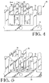
- FIG 4 There is shown in Figure 4 the receptacle bus bar 48 including a carrier strip 70 which is removed just prior to assembly into the housing 42 by blanking along the phantom lines 72.
- a flat pattern of the bus bar as initially blanked and prior to forming is shown in Figure 5 including a root section 74 having a substantially rectangular cross section.
- Four solder tails 54 extend from the side 82 in the same direction as and adjacent the members 80 as shown.
- the members 80 are bent outwardly along an arcuate path for substantially 180 degrees, thereby forming a radius 83, so that the members 80 each have a shank portion 84 that is substantially parallel to the root section 74, as best seen in Figures 4 and 7.
- a second beam 86 extends from and in generally the same direction as the shank 84 and terminates in a contact 88 for each member 80.
- the first beams 76 each terminate in a contact 79 as shown in Figures 6 and 7. While the first and second beams 76 and 86 are not directly opposed but rather are staggered, as best seen in Figure 4, their respective contacts 79 and 88 converge slightly toward an imaginary plane between the two rows of beams. This convergence is chosen so that when the male bus bar 30 is mated to the receptacle bus bar 48, as best seen in Figure 3, the normal force at the point of contact with the contacts 79 and 88 is within the desired range.
- the bus bar 48 is made of phosphorous bronze having a stock thickness of 0.006 inch.
- the root section 74 is about 0.100 inch long and the first beam 76 also is about 0.100 inch long, as viewed in Figure 7.
- the shank portion 84 is about 0.115 inch long and the second beam 86 is about 0.085 inch long.
- the reason that the first beam 76 is long than the second beam 86 is because the first beam is more stiff due to the root section 74 being adjacent the base of the first beam while the base of the second beam is adjacent the shank which has substantially the same width as the beam. This extra length is chosen to compensate for the extra stiffness and thereby substantially equalize the displacement and force of the two contacts 79 and 88 as the male bus 30 is inserted therebetween.
- the contact force in the present example is about 80 grams.
- the root section 74 and shank portion 84 are spaced apart a distance that assures a line to line contact or a slight interference fit with the walls of the slots 56.
- Such line to line contact has the advantage of maintaining the ground bus receptacle 48 in proper position prior to mating with the ground bus 30.
- An important additional advantage is that the characteristic impedance of the connector is more easily controlled because, as set forth in the above mentioned '500 patent, the signal contacts 44 and the ground bus 48 are urged into contact with a common dielectric wall 100,102 as best seen in Figure 3.
- a U-shaped channel 104 is formed in the solder tails 54 along their longitudinal length, as shown in Figure 6.
- the channel 104 which may be V-shaped or some other suitable shape, stiffens the solder tails to help maintain their mutual alignment prior to insertion into the holes 58 in the substrate 59.
- the beams 76 and 86 are staggered so that each space between adjacent first beams 76 is opposed by a second beam 86 and each space between adjacent second beams 86 is opposed by a first beam 76. This is done to facilitate plating of the first and second contacts 79 and 88. As will be appreciated by those skilled in the art, it is difficult to adequately plate opposing contacts that are very close together.
- each member 80 and an adjacent solder tail 54 may be switched yielding opposed beams 76 and 86 and consequently opposed contacts 79 and 88 without departing from the teachings of the present invention.
- the member 80 in the present example, is bent through an arcuate path forming the radius 83, the arcuate path need not follow a radius. It may simply be a pair of right angle bends or a V-shaped bend terminating in a shallow bend on each leg of the V, or some other suitable shape.
- the one-piece ground bus is more easily assembled and is automatically maintained in proper position within the slots in the connector housing prior to assembling and soldering to the printed circuit board. Additionally, the characteristic impedance of the connector is maintained while utilizing a less expensive one-piece ground bus structure.
Landscapes
- Coupling Device And Connection With Printed Circuit (AREA)
- Details Of Connecting Devices For Male And Female Coupling (AREA)
Applications Claiming Priority (2)
| Application Number | Priority Date | Filing Date | Title |
|---|---|---|---|
| US07/835,787 US5161987A (en) | 1992-02-14 | 1992-02-14 | Connector with one piece ground bus |
| US835787 | 1992-02-14 |
Publications (2)
| Publication Number | Publication Date |
|---|---|
| EP0555963A1 true EP0555963A1 (de) | 1993-08-18 |
| EP0555963B1 EP0555963B1 (de) | 1996-08-21 |
Family
ID=25270462
Family Applications (1)
| Application Number | Title | Priority Date | Filing Date |
|---|---|---|---|
| EP93300402A Expired - Lifetime EP0555963B1 (de) | 1992-02-14 | 1993-01-21 | Stecker mit einteiligem Massestreifen |
Country Status (4)
| Country | Link |
|---|---|
| US (1) | US5161987A (de) |
| EP (1) | EP0555963B1 (de) |
| JP (1) | JPH0613134A (de) |
| DE (1) | DE69304094T2 (de) |
Cited By (1)
| Publication number | Priority date | Publication date | Assignee | Title |
|---|---|---|---|---|
| EP0870348A4 (de) * | 1995-12-29 | 1999-12-29 | Molex Inc | Elektrischer verbinderm mit vebesserter erdung |
Families Citing this family (49)
| Publication number | Priority date | Publication date | Assignee | Title |
|---|---|---|---|---|
| US5413491A (en) * | 1993-10-13 | 1995-05-09 | Burndy Corporation | Small form factor connectors with center ground plate |
| JP3112791B2 (ja) * | 1994-01-31 | 2000-11-27 | 富士通株式会社 | コネクタ |
| US5766023A (en) * | 1995-08-04 | 1998-06-16 | Framatome Connectors Usa Inc. | Electrical connector with high speed and high density contact strip |
| JP3631312B2 (ja) * | 1995-12-22 | 2005-03-23 | 富士通コンポーネント株式会社 | 高速信号用コネクタ |
| JP3099111B2 (ja) * | 1996-05-31 | 2000-10-16 | モレックス インコーポレーテッド | リセプタクルコンタクトおよびリセプタクルコンタクトストリップ並びにリセプタクルコンタクトの製造方法 |
| FR2752098B1 (fr) * | 1996-08-02 | 1998-08-28 | Framatome Connectors Int | Ensemble de connecteur |
| FR2752097B1 (fr) * | 1996-08-02 | 1998-08-28 | Framatome Connectors Int | Ensemble de connecteur et element de contact de puissance |
| US5902147A (en) | 1997-03-07 | 1999-05-11 | Circuit Assembly Corp. | Multi-conductor cable connector with integral grounding bus |
| US5971793A (en) * | 1997-06-12 | 1999-10-26 | Circuit Assembly Corp. | Multi-conductor cable connector |
| NO982678L (no) * | 1997-06-26 | 1998-12-28 | Siemens Ag | Pluggkoblingsstykke |
| US5882227A (en) * | 1997-09-17 | 1999-03-16 | Intercon Systems, Inc. | Controlled impedance connector block |
| TW359422U (en) * | 1998-01-24 | 1999-05-21 | Hon Hai Prec Ind Co Ltd | Cable connecting apparatus |
| US5967832A (en) * | 1998-02-23 | 1999-10-19 | 3M Innovative Properties Company | High speed connector assembly |
| US6095821A (en) * | 1998-07-22 | 2000-08-01 | Molex Incorporated | Card edge connector with improved reference terminals |
| US6015299A (en) * | 1998-07-22 | 2000-01-18 | Molex Incorporated | Card edge connector with symmetrical board contacts |
| US6350134B1 (en) * | 2000-07-25 | 2002-02-26 | Tyco Electronics Corporation | Electrical connector having triad contact groups arranged in an alternating inverted sequence |
| US6848944B2 (en) * | 2001-11-12 | 2005-02-01 | Fci Americas Technology, Inc. | Connector for high-speed communications |
| US6558200B1 (en) * | 2002-01-07 | 2003-05-06 | Hon Hai Precision Ind. Co., Ltd. | Card edge connector with commoning contacts and individual contacts and method making the same |
| JP3848300B2 (ja) * | 2003-05-28 | 2006-11-22 | 株式会社アドバンテスト | コネクタ |
| US7281950B2 (en) | 2004-09-29 | 2007-10-16 | Fci Americas Technology, Inc. | High speed connectors that minimize signal skew and crosstalk |
| US7500871B2 (en) * | 2006-08-21 | 2009-03-10 | Fci Americas Technology, Inc. | Electrical connector system with jogged contact tails |
| US7497736B2 (en) | 2006-12-19 | 2009-03-03 | Fci Americas Technology, Inc. | Shieldless, high-speed, low-cross-talk electrical connector |
| US7811100B2 (en) | 2007-07-13 | 2010-10-12 | Fci Americas Technology, Inc. | Electrical connector system having a continuous ground at the mating interface thereof |
| US8251745B2 (en) * | 2007-11-07 | 2012-08-28 | Fci Americas Technology Llc | Electrical connector system with orthogonal contact tails |
| US8764464B2 (en) | 2008-02-29 | 2014-07-01 | Fci Americas Technology Llc | Cross talk reduction for high speed electrical connectors |
| CN102282731B (zh) | 2008-11-14 | 2015-10-21 | 莫列斯公司 | 共振修正连接器 |
| CN102318143B (zh) | 2008-12-12 | 2015-03-11 | 莫列斯公司 | 谐振调整连接器 |
| US9277649B2 (en) | 2009-02-26 | 2016-03-01 | Fci Americas Technology Llc | Cross talk reduction for high-speed electrical connectors |
| US8366485B2 (en) | 2009-03-19 | 2013-02-05 | Fci Americas Technology Llc | Electrical connector having ribbed ground plate |
| US8267721B2 (en) | 2009-10-28 | 2012-09-18 | Fci Americas Technology Llc | Electrical connector having ground plates and ground coupling bar |
| US8616919B2 (en) | 2009-11-13 | 2013-12-31 | Fci Americas Technology Llc | Attachment system for electrical connector |
| JP5623841B2 (ja) * | 2010-09-14 | 2014-11-12 | 日本航空電子工業株式会社 | 電気コネクタ |
| EP2624034A1 (de) | 2012-01-31 | 2013-08-07 | Fci | Abbaubare optische Kupplungsvorrichtung |
| USD718253S1 (en) | 2012-04-13 | 2014-11-25 | Fci Americas Technology Llc | Electrical cable connector |
| US9257778B2 (en) | 2012-04-13 | 2016-02-09 | Fci Americas Technology | High speed electrical connector |
| USD727852S1 (en) | 2012-04-13 | 2015-04-28 | Fci Americas Technology Llc | Ground shield for a right angle electrical connector |
| US8944831B2 (en) | 2012-04-13 | 2015-02-03 | Fci Americas Technology Llc | Electrical connector having ribbed ground plate with engagement members |
| USD727268S1 (en) | 2012-04-13 | 2015-04-21 | Fci Americas Technology Llc | Vertical electrical connector |
| USD751507S1 (en) | 2012-07-11 | 2016-03-15 | Fci Americas Technology Llc | Electrical connector |
| US9543703B2 (en) | 2012-07-11 | 2017-01-10 | Fci Americas Technology Llc | Electrical connector with reduced stack height |
| USD745852S1 (en) | 2013-01-25 | 2015-12-22 | Fci Americas Technology Llc | Electrical connector |
| USD720698S1 (en) | 2013-03-15 | 2015-01-06 | Fci Americas Technology Llc | Electrical cable connector |
| TWI681599B (zh) * | 2014-04-17 | 2020-01-01 | 法商內數位Ce專利控股公司 | 至少一電子配件之電氣接地配件及其電子板和電子裝置 |
| DE112015001539T5 (de) * | 2014-06-23 | 2016-12-22 | Iriso Electronics Co., Ltd. | Verbindungsstruktur eines Verbinders und Verbinder |
| WO2016042625A1 (ja) * | 2014-09-17 | 2016-03-24 | 山一電機株式会社 | プラグ、ソケット、および、それらを備える基板接続用コネクタ |
| EP3101739B1 (de) * | 2015-06-05 | 2022-05-11 | ODU GmbH & Co. KG | Elektrischer verbinder mit stecker und steckdose |
| JP6128702B2 (ja) * | 2015-06-23 | 2017-05-17 | イリソ電子工業株式会社 | コネクタの接続構造及びコネクタ |
| JP6583474B2 (ja) * | 2018-04-27 | 2019-10-02 | 山一電機株式会社 | プラグ、ソケット、および、それらを備える基板接続用コネクタ |
| US11322869B2 (en) * | 2020-05-19 | 2022-05-03 | TE Connectivity Services Gmbh | Electrical connector having a ground bus |
Citations (5)
| Publication number | Priority date | Publication date | Assignee | Title |
|---|---|---|---|---|
| US4710133A (en) * | 1986-06-19 | 1987-12-01 | Trw Inc. | Electrical connectors |
| US4737115A (en) * | 1986-12-19 | 1988-04-12 | North American Specialties Corp. | Solderable lead |
| US4762500A (en) * | 1986-12-04 | 1988-08-09 | Amp Incorporated | Impedance matched electrical connector |
| US4842554A (en) * | 1988-06-03 | 1989-06-27 | Amp Incorporated | One-piece shield for a circular din |
| EP0355947A1 (de) * | 1988-08-18 | 1990-02-28 | The Whitaker Corporation | Elektrische Anschlüsse für ein flaches Starkstromkabel |
Family Cites Families (2)
| Publication number | Priority date | Publication date | Assignee | Title |
|---|---|---|---|---|
| US4824384A (en) * | 1987-03-09 | 1989-04-25 | Amp Incorporated | Electrical cable connector and method of use |
| US4747787A (en) * | 1987-03-09 | 1988-05-31 | Amp Incorporated | Ribbon cable connector |
-
1992
- 1992-02-14 US US07/835,787 patent/US5161987A/en not_active Expired - Lifetime
-
1993
- 1993-01-21 EP EP93300402A patent/EP0555963B1/de not_active Expired - Lifetime
- 1993-01-21 DE DE69304094T patent/DE69304094T2/de not_active Expired - Lifetime
- 1993-02-10 JP JP5044410A patent/JPH0613134A/ja active Pending
Patent Citations (5)
| Publication number | Priority date | Publication date | Assignee | Title |
|---|---|---|---|---|
| US4710133A (en) * | 1986-06-19 | 1987-12-01 | Trw Inc. | Electrical connectors |
| US4762500A (en) * | 1986-12-04 | 1988-08-09 | Amp Incorporated | Impedance matched electrical connector |
| US4737115A (en) * | 1986-12-19 | 1988-04-12 | North American Specialties Corp. | Solderable lead |
| US4842554A (en) * | 1988-06-03 | 1989-06-27 | Amp Incorporated | One-piece shield for a circular din |
| EP0355947A1 (de) * | 1988-08-18 | 1990-02-28 | The Whitaker Corporation | Elektrische Anschlüsse für ein flaches Starkstromkabel |
Cited By (1)
| Publication number | Priority date | Publication date | Assignee | Title |
|---|---|---|---|---|
| EP0870348A4 (de) * | 1995-12-29 | 1999-12-29 | Molex Inc | Elektrischer verbinderm mit vebesserter erdung |
Also Published As
| Publication number | Publication date |
|---|---|
| DE69304094T2 (de) | 1997-03-20 |
| US5161987A (en) | 1992-11-10 |
| JPH0613134A (ja) | 1994-01-21 |
| DE69304094D1 (de) | 1996-09-26 |
| EP0555963B1 (de) | 1996-08-21 |
Similar Documents
| Publication | Publication Date | Title |
|---|---|---|
| EP0555963B1 (de) | Stecker mit einteiligem Massestreifen | |
| EP0436943B1 (de) | Verbesserter Leiterplattenrandverbinder | |
| US5026292A (en) | Card edge connector | |
| US4975084A (en) | Electrical connector system | |
| US5582519A (en) | Make-first-break-last ground connections | |
| US5112233A (en) | Electrical connector having contact retention means | |
| US6293827B1 (en) | Differential signal electrical connector | |
| US6250935B1 (en) | Electrical connector | |
| US5085601A (en) | Reduced insertion force electrical connector | |
| EP1190469B1 (de) | Modularer elektrischer verbinder und verbindungssystem | |
| US4428636A (en) | Multi-contact connectors for closely spaced conductors | |
| EP0951102B1 (de) | Leistungsverbinder | |
| US6343951B1 (en) | Electrical connector | |
| EP0746060A2 (de) | Abgeschirmter Rückwandsteckverbinder | |
| US20060063432A1 (en) | Shielded electrical connector assembly | |
| EP0717468B1 (de) | Zuerst Polkontakte zuletzt Erdkontakt unterbrechender Steckverbinder | |
| CA2280174A1 (en) | High speed, high density electrical connector | |
| EP0365179B1 (de) | Elektrisches Verbindersystem | |
| US5536179A (en) | Electrical connector with ground bus insert | |
| GB2296829A (en) | Printed circuit board connector | |
| US7229298B2 (en) | Electrical connector having an improved grounding path | |
| EP0996993B1 (de) | Verriegelte und abgeschirmte elektrische verbinder | |
| US5219295A (en) | Electrical connector with guide member | |
| EP0455367A2 (de) | Rechtwinklig abgebogener impedanzangepasster Steckverbinder | |
| JPH0748384B2 (ja) | プリント基板用の表面実装電気コネクタ |
Legal Events
| Date | Code | Title | Description |
|---|---|---|---|
| PUAI | Public reference made under article 153(3) epc to a published international application that has entered the european phase |
Free format text: ORIGINAL CODE: 0009012 |
|
| AK | Designated contracting states |
Kind code of ref document: A1 Designated state(s): DE FR GB IT NL |
|
| 17P | Request for examination filed |
Effective date: 19940215 |
|
| 17Q | First examination report despatched |
Effective date: 19950821 |
|
| GRAH | Despatch of communication of intention to grant a patent |
Free format text: ORIGINAL CODE: EPIDOS IGRA |
|
| GRAH | Despatch of communication of intention to grant a patent |
Free format text: ORIGINAL CODE: EPIDOS IGRA |
|
| GRAA | (expected) grant |
Free format text: ORIGINAL CODE: 0009210 |
|
| AK | Designated contracting states |
Kind code of ref document: B1 Designated state(s): DE FR GB IT NL |
|
| ITF | It: translation for a ep patent filed | ||
| REF | Corresponds to: |
Ref document number: 69304094 Country of ref document: DE Date of ref document: 19960926 |
|
| ET | Fr: translation filed | ||
| PLBE | No opposition filed within time limit |
Free format text: ORIGINAL CODE: 0009261 |
|
| 26N | No opposition filed | ||
| PGFP | Annual fee paid to national office [announced via postgrant information from national office to epo] |
Ref country code: NL Payment date: 19981222 Year of fee payment: 7 |
|
| PG25 | Lapsed in a contracting state [announced via postgrant information from national office to epo] |
Ref country code: NL Free format text: LAPSE BECAUSE OF NON-PAYMENT OF DUE FEES Effective date: 20000801 |
|
| NLV4 | Nl: lapsed or anulled due to non-payment of the annual fee |
Effective date: 20000801 |
|
| REG | Reference to a national code |
Ref country code: GB Ref legal event code: IF02 |
|
| PGFP | Annual fee paid to national office [announced via postgrant information from national office to epo] |
Ref country code: FR Payment date: 20120130 Year of fee payment: 20 |
|
| PGFP | Annual fee paid to national office [announced via postgrant information from national office to epo] |
Ref country code: DE Payment date: 20120127 Year of fee payment: 20 |
|
| PGFP | Annual fee paid to national office [announced via postgrant information from national office to epo] |
Ref country code: IT Payment date: 20120124 Year of fee payment: 20 Ref country code: GB Payment date: 20120126 Year of fee payment: 20 |
|
| REG | Reference to a national code |
Ref country code: DE Ref legal event code: R071 Ref document number: 69304094 Country of ref document: DE |
|
| REG | Reference to a national code |
Ref country code: GB Ref legal event code: PE20 Expiry date: 20130120 |
|
| PG25 | Lapsed in a contracting state [announced via postgrant information from national office to epo] |
Ref country code: GB Free format text: LAPSE BECAUSE OF EXPIRATION OF PROTECTION Effective date: 20130120 Ref country code: DE Free format text: LAPSE BECAUSE OF EXPIRATION OF PROTECTION Effective date: 20130122 |