EP0557184B1 - Verfahren zum Anbringen eines Farbbandes in einem Kassettengehäuse und Farbbandkassette dazu anwendbar - Google Patents
Verfahren zum Anbringen eines Farbbandes in einem Kassettengehäuse und Farbbandkassette dazu anwendbar Download PDFInfo
- Publication number
- EP0557184B1 EP0557184B1 EP93400389A EP93400389A EP0557184B1 EP 0557184 B1 EP0557184 B1 EP 0557184B1 EP 93400389 A EP93400389 A EP 93400389A EP 93400389 A EP93400389 A EP 93400389A EP 0557184 B1 EP0557184 B1 EP 0557184B1
- Authority
- EP
- European Patent Office
- Prior art keywords
- supporting member
- hole
- core
- cores
- ink ribbon
- Prior art date
- Legal status (The legal status is an assumption and is not a legal conclusion. Google has not performed a legal analysis and makes no representation as to the accuracy of the status listed.)
- Expired - Lifetime
Links
- 238000000034 method Methods 0.000 title claims description 14
- 239000011347 resin Substances 0.000 description 1
- 229920005989 resin Polymers 0.000 description 1
Images


Classifications
-
- B—PERFORMING OPERATIONS; TRANSPORTING
- B41—PRINTING; LINING MACHINES; TYPEWRITERS; STAMPS
- B41J—TYPEWRITERS; SELECTIVE PRINTING MECHANISMS, i.e. MECHANISMS PRINTING OTHERWISE THAN FROM A FORME; CORRECTION OF TYPOGRAPHICAL ERRORS
- B41J32/00—Ink-ribbon cartridges
Definitions
- the present invention generally relates to a method for setting an ink ribbon into a cassette body and an ink ribbon cassette to which the method is applicable, and more particularly to a method for enabling to easily set an ink ribbon into a cassette body, and to an ink ribbon cassette in which an ink ribbon can be easily replaced.
- an ink ribbon is wound to a supply ribbon core and an end of the ink ribbon is fixed on a take-up ribbon core.
- Both the supply ribbon core and the take-up ribbon core are rotatably mounted in a cassette body. While a printing operation is being performed, the supply ribbon core and the take-up ribbon core are rotated in a predetermined direction so that the ink ribbon moves from the supply ribbon core to the take-up ribbon core. The ink ribbon is thus wound to the take-up ribbon core.
- the supply ribbon core and the take-up ribbon core to which a used ink ribbon has been wound are removed from the cassette body, and a new supply ribbon core, having a new ink ribbon wound thereon, and a new take-up ribbon core are set therein.
- the supply ribbon core and the take-up ribbon core are separately removed from the cassette body and separately set therein.
- the ink ribbon may no longer be used in the printer.
- the supply core and the take-up core may be removed from the setting positions.
- a general object of the present invention is to provide a novel and useful ink ribbon cassette in which the disadvantages of the aforementioned prior art are eliminated.
- a more specific object of the present invention is to provide a method for setting an ink ribbon into a cassette body by which method the ink ribbon can be easily set into the cassette body.
- the above objects of the present invention are achieved by a method for setting an ink ribbon wound to a first core and a second core into a cassette body having a bottom plate on which a setting hole is formed, the setting hole being divided into a first hole part for rotatably supporting the first core, a second hole part for rotatably supporting the second core, and a third hole part connecting the first and second hole parts which are at a predetermined distance from each other, the method comprising the steps of: (a) setting an assembly into the setting hole formed on the bottom plate of the cassette body, the assembly being formed of the first and second cores on which the ink ribbon is wound and a supporting member detachably supporting the first and second cores, a distance between the first and second cores supported by the supporting member corresponding to the distance between the first and second hole parts formed on the bottom plate of the cassette body; (b) detaching the supporting member from the first and second cores; and (c) drawing the supporting member from the cassette body through the setting hole, so that the first and second cores remain
- the first and second cores to which the ink ribbon is wound are set in the cassette body using the supporting member supporting the first and second cores a predetermined distance from each other.
- the first and second cores can be easily set into the cassette body.
- Another object of the present invention is to provide an ink ribbon cassette in which an ink ribbon can be easily replaced.
- an ink ribbon cassette comprising: a cassette body having a bottom plate on which a setting hole is formed, the setting hole being divided into a first hole part, a second hole part, and a third hole part connecting the first and second hole parts which are at a predetermined distance from each other; a first core detachably set rotatably in the first hole part of the setting hole formed on the bottom plate of the cassette body; a second core detachably set rotatably in the second hole part of the setting hole; and an ink ribbon wound on the first and second cores, wherein an assembly formed of the first and second cores and a supporting member detachably supporting the first and second cores can be set into the setting hole formed on the bottom plate of the cassette body, and once the supporting member is detached from the first and second cores the supporting member can then be drawn from the cassette body through the setting hole.
- the first and second cores on which the ink ribbon is wound can be replaced using the supporting member supporting the first and second cores at a predetermined distance from each other.
- the first and second cores can be easily replaced.
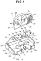
- FIG.1 is a perspective view illustrating an ink ribbon cassette according to an embodiment of the present invention.
- FIG.2 is a perspective view illustrating a supporting member for a supply ribbon core and a take-up ribbon core.
- FIGS.3 and 4 are cross sectional views illustrating operations of the supporting member.
- FIG.5 is a cross sectional view illustrating a state where the supporting member rotatably supports the supply ribbon core and the take-up core.
- FIGS.1 through FIG.5 A description will now be given, with reference to FIGS.1 through FIG.5, of an embodiment of the present invention.
- FIG.1 An ink ribbon cassette according to the embodiment of the present invention is formed as shown in FIG.1.
- the ink ribbon cassette has a cassette body 10 and an ink ribbon roll assembly 30.
- the ink ribbon roll assembly 30 can be mounted in the cassette body 10 and can be removed therefrom. That is, the ink ribbon roll assembly 30 mounted in the cassette body 10 can be replaced.
- the ink ribbon roll assembly 30 comprises a supply ribbon core 31, a take-up ribbon core 32 and an ink ribbon 33.
- the ink ribbon 33 is wound to the supply ribbon core 31 and an end of the ink ribbon 33 is fixed on the take-up core 32.
- the supply core 31 and the take-up core 32 are short.
- a supporting member 40 is engaged with the ink roll assembly 30.
- the supporting member 40 is made of resin having an elastic property, and is shaped as shown in FIG.2. That is, the supporting member 40 is formed of a plate doubled up in a V-shape and has a pinching part 43 and supporting parts 41 and 42.
- the supporting parts 41 and 42 are formed at ends of the pinching part 43 so as to be parallel to each other.
- the pinching part 43 extends in a direction perpendicular to each of the supporting parts 41 and 42.
- the supporting parts 41 and 42 are respectively provided with core engaging parts 41a and 42a.
- the width of the plate corresponding to each of the core engaging parts 41a and 42a is less than the width of the plate corresponding to other portions of the supporting parts 41 and 42.
- stopper steps 45 are formed at the bases of the core engaging parts 41a and 42a.
- the width of the plate corresponding to each of the core engaging parts 41a and 42a is less than the inside diameter of the supply ribbon core 31 and less than that of the take-up ribbon core 32, and the width of the plate corresponding to the other positions of the supporting parts 41 and 42 is greater than the inside diameter of the supply ribbon core 31 and than that of the take-up ribbon core 32.
- Flanges 41b and 42b project, at the ends of the core engaging parts 41a and 42a, from the surface of the core engaging parts 41a and 42a to the outside.
- the pinching part 43 is provided with a projection 46 at the center thereof.
- the supporting member 40 When the pinching part 43 of the supporting member 40 is pinched by fingers, the supporting member 40 is folded. In this folded state, the core engaging parts 41a and 42a are respectively inserted into the supply ribbon core 31 and into the take-up ribbon core 32 until the bottom surfaces of the supply ribbon core 31 and the take-up ribbon core 32 are brought into contact with the stopper steps 45 of the supporting parts 41 and 42, as shown in FIG.3. In this state, the flanges 41b and 42b provided at the ends of the engaging parts 41a and 42a are respectively out of the supply ribbon core 31 and the take-up ribbon core 32.
- the supporting member 40 expands due to the repulsion force of the supporting member 40 which has been folded, so as to become the V-shape.
- the flanges 41b and 42b are respectively engaged with rims of the supply ribbon core 31 and the take-up ribbon core 32, as shown in FIG.4.
- the supply ribbon core 31 and the take-up ribbon core 32 are respectively sandwiched between the flanges 41b and 42b and the stopper steps 45. That is, the supporting member 40 is engaged with the ink ribbon roll assembly 30, so that the distance between the supply ribbon core 31 and the take-up ribbon core 32 is maintained at a predetermined distance due to the support from the supporting parts 41 and 42 of the supporting member 40.
- the cassette body 10 has a bottom plate 10a, a lid 10b and walls 10c-10e provided on edges of the bottom plate 10a so as to surround the bottom plate 10a.
- the walls include a rear wall 10c, side walls 10d and a front wall 10e.
- An edge of the lid 10b is connected to the rear wall 10c so that the lid 10b can open and close.
- the cassette body 10 is made by a plastic mold forming process.
- First core receiving holes 11a and 12a are formed on the bottom plate 10a. The distance between the core-receiving holes 11a and 12a corresponds to the distance between the supporting parts 41a and 42a of the supporting member 40.
- Second core-receiving holes 11b and 12b are formed on the lid 10b so as to respectively face the first core-receiving holes 11a and 12a in a state where the lid 10a is closed.
- the supply ribbon core 31 and the take-up ribbon core 32 are respectively engaged with the first and second core-receiving holes 11a and 11b and 12a and 12b so as to be rotatable.
- a longitudinal hole 20 is formed on the bottom plate 10a so as to connect the first receiving holes 11a and 12a.
- the longitudinal hole 20 has a corresponding area sufficient for the pinching part 43 of the supporting member 40 to pass through the hole 20.
- a notch 21 is formed at the center of an edge of the longitudinal hole 20 so that the shape of the longitudinal hole 20 is asymmetrical with respect to a center line L thereof.
- the notch 21 can be engaged with the projection 46 formed on the pinching part 43 of the supporting member 40.
- Windows are formed on the front wall 10e at the center of the wall 10e and at both sides thereof.
- One of the windows formed at the sides of the front wall 10e is used as a ribbon end detecting window 16 through which a ribbon end-mark formed on the ink ribbon may be detected.
- Guide poles 13 project from the bottom plate 10a so as to provide one guide pole 13 across each of the ends of the window at the center of the front wall 10e.
- a C-shaped guide plate 14 projects from the lid 10b so as to correspond to the window at the center of the front wall 10e.
- Guide plates 15 project from the lid 10b so as to provided one guide plate 15 accross each of the windows at the sides of the front wall 10e.
- the front edge of the bottom plate 10a is provided with a click 17.
- a hole 18 is formed at the center of the C-shaped guide plate 14. In a state where the lid 10b is closed, the click 17 is engaged in the hole 18 so that the lid 10b is locked.
- the ribbon roll assembly 30 is set in the cassette body 10 as follows.
- the supporting member 40 has been engaged with the ribbon roll assembly 30. In this state, the supporting member 40 is inserted into the first core-receiving holes 11a and 12a and the longitudinal hole 20 which holes are formed on the bottom plate 10a of the cassette body 10. At this time, if the projection 46 formed on the pinching part 43 of the supporting member 40 faces the rear wall 10c, the supporting member 40 is not insertable into the holes 11a, 11b and 20. Only when the projection 46 is engaged with the notch 21 (the projection 46 faces the front wall 10e), the supporting member 40 can be inserted into the holes 11a, 12a and 20. Then, the supporting member 40 is out of the bottom plate 10a, as shown in FIG.5.
- the ink ribbon 33 is made more slack so as to loosely extend along the ribbon running path and be guided by the guide poles 13.
- the pinching part 43 protruding outside of the longitudinal hole 20 formed on the bottom plate 10a is strongly pinched by the fingers so that the supporting member 40 is folded as shown in FIG.3.
- the supporting member 40 is pulled, the supporting parts 41a and 42a of the supporting member 40 are detached from the supply ribbon core 31 and the take-up ribbon core, and the supporting member 40 is drawn from the cassette body 10 through the first core-receiving holes 11a and 12a and the longitudinal hole 20.
- the supply ribbon core 31 and the take-up ribbon core 32 are respectively engaged in the first bore-receiving holes 11a and 12a. Then, the lid 10b is closed and the click 17 is engaged with the hole 18 so that the lid 10b is locked. Thereafter, the ink ribbon assembly 30 is completely set in the cassette body 10.
- the distance between the supply ribbon core 31 and the take-up ribbon core 32 is maintained constant during the setting of the ribbon roll assembly 30 into the cassette body 10.
- the ribbon roll assembly 30 can be easily set into the cassette 10 using only one hand.
- the projection 46 formed on the supporting member 40 is not engaged in the notch 21 formed in the longitudinal hole 20, it is not possible to set the ribbon roll assembly 30 into the cassette body 10.
- the ribbon roll assembly 30 is prevented from being set in an incorrect direction.
Landscapes
- Impression-Transfer Materials And Handling Thereof (AREA)
Claims (13)
- Verfahren zum Einsetzen eines Farbbandes (33), das auf einen ersten Kern (31) und einen zweiten Kern (32) aufgewickelt ist, in einen Kassettenkörper (10), der eine Bodenplatte (10a) hat, an der ein Einsetzloch (11a, 12a, 20) ausgebildet ist, wobei das Einsetzloch (11a, 12a, 20) in einen ersten Lochteil (11a) zum drehbaren Unterstützen des ersten Kerns (31), einen zweiten Lochteil (12a) zum drehbaren Unterstützen des zweiten Kerns (32) und einen dritten Lochteil (20) aufgeteilt ist, der die ersten und zweiten Lochteile (11a) (12a) verbindet, die in einem vorbestimmten Abstand voneinander sind, wobei das Verfahren die Schritte enthält:(a) Einsetzen einer Anordnung (30, 40) in das Einsetzloch (11a, 12a, 20), das an der Bodenplatte (10a) des Kassettenkörpers (10) ausgebildet ist, wobei die Anordnung (30, 40) aus den ersten und zweiten Kernen (31, 32), auf die das Farbband (33) aufgewickelt ist, und einem Halteelement (40) ausgebildet ist, das die ersten und zweiten Kerne (31) (32) lösbar hält, wobei ein Abstand zwischen den ersten und zweiten Kernen (31) (32), die von dem Halteelement (40) gehalten werden, dem Abstand zwischen den ersten und zweiten Lochteilen (11a) (12a) entspricht, die in der Bodenplatte (10a) des Kassettenkörpers (10) ausgebildet sind,(b) Lösen des Halteelements (40) von den ersten und zweiten Kernen (31) (32), und(c) Wegziehen des Halteelements (40) vom Kassettenkörper (10) durch das Einsetzloch (11a, 12a, 20), so daß die ersten und zweiten Kerne (31) (32) in dem Kassettenkörper (10) in einem Zustand verbleiben, in dem die ersten und zweiten Kerne (31) (32) jeweils in die ersten und zweiten Lochteile (11a) (12a) eingesetzt sind, die in der Bodenplatte (10a) des Kassettenkörpers (10) ausgebildet sind.
- Verfahren nach Anspruch 1, ferner enthaltend den Schritt:(a') Ausbilden der Anordnung (30, 40) derart, daß das Halteelement (40) die ersten und zweiten Kerne (31) (32) lösbar hält, wobei der Schritt (a') vor dem Schritt (a) ausgeführt wird.
- Farbbandkassette dadurch gekennzeichnet, daß vorgesehen sind:
ein Kassettenkörper (10) mit einer Bodenplatte (10a), an der ein Einsetzloch (11a, 12a, 20) ausgebildet ist, wobei das Einsetzloch (11a, 12a, 20) in einen ersten Lochteil (11a), einen zweiten Lochteil (12a) und einen dritten Lochteil (20) geteilt ist, der die ersten und zweiten Lochteile (11a) (12a) verbindet, die in einem vorgegebenen Abstand voneinander sind;
ein erster Kern (31), der lösbar und drehbar in den ersten Lochteil (11a) des an der Bodenplatte (10a) des Kassettenkörpers (10) ausgebildeten Einsetzlochs (11a, 12a, 20) eingesetzt ist;
ein zweiter Kern (32), der lösbar und drehbar in den zweiten Lochteil (12a) des Einsetzlochs (11a, 12a, 20) eingesetzt ist; und
ein Farbband (33), das auf die ersten und zweiten Kerne (31) (32) aufgewickelt ist,
wobei eine Anordnung (30, 40), die aus den ersten und zweiten Kernen (31) (32) und einem Halteelement (40) gebildet ist, das die ersten und zweiten Kerne (31) (32) lösbar hält, in das Einsetzloch (11a, 12a, 20) eingesetzt werden kann, das an der Bodenplatte (10a) des Kassettenkörpers (10) ausgebildet ist, und das Halteelement (40) von den ersten und zweiten Kernen (31) (32) gelöst wird und durch das Einsetzloch (11a, 12a, 20) vom Kassettenkörper (10) weg gezogen werden kann. - Farbbandkassette nach Anspruch 3, dadurch gekennzeichnet, daß eine Form des dritten Lochteils (20) des Einsetzlochs (11a, 12a, 20) asymmetrisch bezüglich einer Linie (L) parallel zu einer Richtung ist, in der die ersten und zweiten Kerne (31) (32) in dem Kassettenkörper (10) angeordnet sind.
- Farbbandkassette nach Anspruch 4, dadurch gekennzeichnet, daß eine Kerbe (21) an einer Kante des dritten Lochteils (20) des Einsetzlochs (11a, 12a, 20) ausgebildet ist.
- Anordnung (40), enthaltend:
einen ersten Kern (31),
einen zweiten Kern (32),
ein Farbband (33), das auf die ersten und zweiten Kerne (31) (32) aufgewickelt ist, und
ein Halteelement (40) zum lösbaren Halten der ersten und zweiten Kerne (31) (32), die in einem vorgegebenen Abstand voneinander sind,
wobei die Anordnung (30, 40) in ein Einsetzloch (11a, 12a, 20) eingesetzt werden kann, das an der Bodenplatte (10a) einer Farbbandkassette ausgebildet ist, wobei das Einsetzloch (11a, 12a, 20) in einen ersten Lochteil (11a) zum drehbaren Halten des ersten Kerns (31), einen zweiten Lochteil (12a) zum drehbaren Halten des zweiten Kerns (32) und einen dritten Lochteil (20) geteilt ist, der die ersten und zweiten Lochteile (11a) (12a) in einem Abstand hält, der dem Abstand zwischen den ersten und zweiten Kernen (31) (32) entspricht, die von dem Halteelement (40) gehalten werden, wobei das Halteelement (40) von den ersten und zweiten Kernen (31) (32) lösbar ist und in der Lage ist, durch das Einsetzloch (11a, 12a, 20) von der Farbbandkassette weg gezogen zu werden. - Anordnung nach Anspruch 6, dadurch gekennzeichnet, daß das Halteelement (40) aus einer Platte besteht, die in einer V-Form (Fig. 2) geformt ist, das Halteelement (40) einen Zusammendrückteil (43) und Halteteile (41) (42) hat, die an Enden des Zusammendrückteils (43) ausgebildet sind, und wobei die Halteteile (41) (42) eingesetzt werden in die und losgelöst werden von den Kerne(n) (31) (32) in einem Zustand, in dem das Halteelement (40) mittels Zusammendrückens des Zusammendrückteils (43) gefaltet ist (Fig. 3) und die Halteteile (41) (42) mit den ersten und zweiten Kernen (31) (32) in einem Zustand in Eingriff sind, in dem das Halteelement (40) sich ausgedehnt hat, so daß es aufgrund einer Repulsionskraft des Halteelements (40) die V-Form (Fig. 4) annimmt.
- Anordnung nach Anspruch 6, dadurch gekennzeichnet, daß eine Form des Halteelements (40) asymmetrisch zu einer Ebene ist, die eine Linie parallel zu einer Richtung enthält, in der die ersten und zweiten Kerne (31) (32) anzuordnen sind, wobei die Ebene parallel zu einer Richtung ist, in der das Halteelement (40) die ersten und zweiten Kerne (31) (32) hält, und wobei die Anordnung (30, 40) in das Einsetzloch (11a, 12a, 20) eingesetzt werden kann, das eine Form entsprechend der Form des Halteelements (40) hat.
- Anordnung nach Anspruch 8, dadurch gekennzeichnet, daß das Halteelement (40) einen Vorsprung (46) hat, der an einer Oberfläche davon ausgebildet ist.
- Halteelement (40) zum Halten eines ersten Kerns und eines zweiten Kerns, auf die ein Farbband aufgewickelt ist, dadurch gekennzeichnet, daß das Halteelement (40) enthält:
einen ersten Teil (41) zum lösbaren Halten des ersten Kerns (31),
einen zweiten Teil (42) zum lösbaren Halten des zweiten Kerns (32), und
einen dritten Teil (43), der den ersten Teil (41) und den zweiten Teil (42) verbindet, die in einem vorgegebenen Abstand voneinander sind,
wobei eine Anordnung (30, 40), die aus dem Halteelement (40) und den ersten und zweiten Kernen (31) (32) gebildet ist, in ein Einsetzloch (11a, 12a, 20) eingesetzt werden kann, das an einer Bodenplatte (10a) einer Farbbandkassette ausgebildet ist, wobei das Einsetzloch (11a, 12a, 20) in einen ersten Lochteil (11a) zum drehbaren Halten des ersten Kerns (31), einen zweiten Lochteil (12a) zum drehbaren Halten des zweiten Kerns (32) und einen dritten Lochteil (20) geteilt ist, der die ersten und zweiten Lochteile (11a) (12a) in einem Abstand verbindet, der dem Abstand zwischen den ersten und zweiten Teilen (41) (42) des Halteelements (40) entspricht, wobei das Halteelement (40) von den ersten und zweiten Kernen (31) (32) lösbar ist und in der Lage ist, von der Farbbandkassette durch das Einsetzloch (11a, 12a, 20) wegziehbar zu sein. - Halteelement nach Anspruch 10, dadurch gekennzeichnet, daß das Halteelement (40) aus einer Platte besteht, die in einer V-Form gebildet ist (Fig. 2), und wobei erste und zweite Teile (41) (42) eingesetzt werden können in die und losgelöst werden können von den ersten und zweiten Kerne(n) (31) (32) in einem Zustand, in dem das Halteelement (40) durch Zusammendrücken des dritten Teils (43) gefaltet ist (Fig. 3), und die Halteteile (41) (42) mit den ersten und zweiten Kernen (31) (32) in einem Zustand in Eingriff sind, in dem das Halteelement (40) ausgedehnt ist, so daß es durch die Repulsionskraft des Halteelements (40) die V-Form (Fig. 4) annimmt.
- Halteelement nach Anspruch 10, dadurch gekennzeichnet, daß eine Form des Halteelements (40) asymmetrisch zu einer Ebene ist, die eine Linie parallel zu einer Richtung enthält, in der die ersten und zweiten Kerne (31) (32) anzuordnen sind, wobei die Ebene parallel zu einer Richtung ist, in der das Halteelement (40) die ersten und zweiten Kerne (31) (32) hält, und wobei die Anordnung (30, 40) in das Einsetzloch (11a, 12a, 20) eingesetzt werden kann, das eine Form entsprechend der Form des Halteelements (40) hat.
- Halteelement nach Anspruch 12, dadurch gekennzeichnet, daß der dritte Teil (43) einen Vorsprung (46) hat, der an einer Oberfläche davon ausgebildet ist.
Applications Claiming Priority (2)
| Application Number | Priority Date | Filing Date | Title |
|---|---|---|---|
| JP30563/92 | 1992-02-18 | ||
| JP4030563A JP2901798B2 (ja) | 1992-02-18 | 1992-02-18 | インクリボンカセット及びそのインクリボン交換方法 |
Publications (3)
| Publication Number | Publication Date |
|---|---|
| EP0557184A2 EP0557184A2 (de) | 1993-08-25 |
| EP0557184A3 EP0557184A3 (de) | 1994-02-02 |
| EP0557184B1 true EP0557184B1 (de) | 1996-05-29 |
Family
ID=12307290
Family Applications (1)
| Application Number | Title | Priority Date | Filing Date |
|---|---|---|---|
| EP93400389A Expired - Lifetime EP0557184B1 (de) | 1992-02-18 | 1993-02-17 | Verfahren zum Anbringen eines Farbbandes in einem Kassettengehäuse und Farbbandkassette dazu anwendbar |
Country Status (5)
| Country | Link |
|---|---|
| US (1) | US5248208A (de) |
| EP (1) | EP0557184B1 (de) |
| JP (1) | JP2901798B2 (de) |
| KR (1) | KR960015765B1 (de) |
| DE (1) | DE69302840T2 (de) |
Families Citing this family (12)
| Publication number | Priority date | Publication date | Assignee | Title |
|---|---|---|---|---|
| KR940004617A (ko) * | 1992-08-28 | 1994-03-15 | 최준식 | 테이프릴용 아답터 |
| JP2968411B2 (ja) * | 1993-04-07 | 1999-10-25 | アルプス電気株式会社 | インクリボン交換用アタッチメント |
| FR2713552B1 (fr) * | 1993-12-15 | 1996-02-09 | Sagem | Sabot de chargement de ruban encreur pour imprimante à impression par transfert thermique. |
| GB9401544D0 (en) * | 1994-01-27 | 1994-03-23 | Ici Plc | Thermal transfer ribbon cassette system |
| US5487615A (en) * | 1994-10-28 | 1996-01-30 | Sercomp Corporation | Ribbon drive assembly for ribbon cartridge |
| US9539834B2 (en) * | 2012-03-05 | 2017-01-10 | Yuyama Mfg. Co., Ltd. | Medicine packaging device, ink ribbon running control method, ink ribbon roll and ink ribbon cassette |
| CN103009833B (zh) * | 2012-12-10 | 2015-09-09 | 佛山市顺德区高宝实业发展有限公司 | 平台机入带模式生产色带架工艺 |
| CN103332027B (zh) * | 2013-06-28 | 2015-05-06 | 上海宜达胜电脑用品有限公司 | 一种具有可脱卸式色带内盒的打印机色带盒 |
| CN103317867B (zh) * | 2013-06-28 | 2015-07-15 | 上海宜达胜电脑用品有限公司 | 一种针式打印机的组装式色带盒 |
| CN103332028B (zh) * | 2013-06-28 | 2016-04-13 | 上海宜达胜电脑用品有限公司 | 一种针式打印机的可多次使用的色带盒 |
| CN103386826B (zh) * | 2013-06-28 | 2016-04-13 | 上海宜达胜电脑用品有限公司 | 一种针式打印机的色带盒的连接卡扣 |
| NL2013903B1 (nl) * | 2014-12-02 | 2016-10-11 | Stomydo B V | Houder voor een stoma-verband. |
Family Cites Families (12)
| Publication number | Priority date | Publication date | Assignee | Title |
|---|---|---|---|---|
| US3151724A (en) * | 1962-02-13 | 1964-10-06 | Royal Mcbee Corp | Typewriter ribbon package |
| US3520495A (en) * | 1966-10-29 | 1970-07-14 | Tadashi Sotani | Tape cartridge and driving mechanism for the tape |
| US3581864A (en) * | 1968-12-23 | 1971-06-01 | Walter D Landgraf | Ribbon lock for typewriter spools |
| US3977511A (en) * | 1975-04-02 | 1976-08-31 | Triumph Werke Nurnberg A.G. | Ribbon loading device |
| GB1535396A (en) * | 1976-05-21 | 1978-12-13 | Grafton & Son Walter | Support means for cassettes or cartridges for inked or filmed ribbons |
| US4367963A (en) * | 1980-07-21 | 1983-01-11 | Wordex | Refillable typewriter ribbon cartridge |
| IT8353197U1 (it) * | 1983-04-13 | 1984-10-13 | Olivetti & Co Spa | Cartuccia per un nastro di scrittura di macchine per scrivere. |
| DE3741361A1 (de) * | 1987-12-07 | 1989-06-15 | Triumph Adler Ag | Traeger eines farbbandes fuer schreib- und aehnliche maschinen |
| DE3741362A1 (de) * | 1987-12-07 | 1989-06-15 | Triumph Adler Ag | Traeger eines farbbandes mit vorrats- und aufwickelspule fuer schreib- und aehnliche maschinen |
| JP2570399B2 (ja) * | 1988-08-11 | 1997-01-08 | 富士通株式会社 | インクリボンの装填方法 |
| US4974977A (en) * | 1989-01-19 | 1990-12-04 | Banctec, Inc. | Print ribbon cartridge with vacuum buffer chambers |
| JP2786897B2 (ja) * | 1989-08-28 | 1998-08-13 | アルプス電気株式会社 | リボンカセット |
-
1992
- 1992-02-18 JP JP4030563A patent/JP2901798B2/ja not_active Expired - Fee Related
-
1993
- 1993-02-12 US US08/017,260 patent/US5248208A/en not_active Expired - Fee Related
- 1993-02-16 KR KR1019930002103A patent/KR960015765B1/ko not_active Expired - Fee Related
- 1993-02-17 EP EP93400389A patent/EP0557184B1/de not_active Expired - Lifetime
- 1993-02-17 DE DE69302840T patent/DE69302840T2/de not_active Expired - Fee Related
Also Published As
| Publication number | Publication date |
|---|---|
| DE69302840T2 (de) | 1996-10-02 |
| DE69302840D1 (de) | 1996-07-04 |
| JPH05221106A (ja) | 1993-08-31 |
| KR960015765B1 (ko) | 1996-11-21 |
| KR930017724A (ko) | 1993-09-20 |
| JP2901798B2 (ja) | 1999-06-07 |
| EP0557184A2 (de) | 1993-08-25 |
| US5248208A (en) | 1993-09-28 |
| EP0557184A3 (de) | 1994-02-02 |
Similar Documents
| Publication | Publication Date | Title |
|---|---|---|
| EP0557184B1 (de) | Verfahren zum Anbringen eines Farbbandes in einem Kassettengehäuse und Farbbandkassette dazu anwendbar | |
| CN106232372B (zh) | 具有强化介质及色带装卸特征的介质处理设备 | |
| EP1808302A2 (de) | Bandkassette | |
| EP2628601B1 (de) | Rollband und Drucker | |
| JP7073846B2 (ja) | 印刷カートリッジ、テープガイドおよび印刷装置 | |
| EP1147909A2 (de) | Drucker zum Unterbringen von aufgewickeltem Papier unterschiedlicher Breiten | |
| RU2218278C2 (ru) | Кассета для красящей ленты, которая может использоваться в построчном термопереносном печатающем устройстве | |
| JP3441485B2 (ja) | テープカセット | |
| EP0654358B1 (de) | Transferdrucker | |
| JP6398932B2 (ja) | リボンカセット | |
| US3481445A (en) | Cartridge ribbon supply | |
| US4990006A (en) | Holder of a ribbon for typewriters or similar machines | |
| EP1172223B1 (de) | Tintenkassette, Farbbandcontainer und Verfahren zum Montieren eines Farbbandes in eine Tintenkassette | |
| JP4710162B2 (ja) | プリンタ | |
| JPS6083879A (ja) | 印字装置 | |
| JP2581407B2 (ja) | インクリボンカセットおよびその装着構造 | |
| JPH08310713A (ja) | 塗布具 | |
| EP0595265A2 (de) | Gerät und Verfahren zum Laden eines Farbstoffträgers in einen Wärmedrucker | |
| JP2538541Y2 (ja) | アーム部材付きサブカセット | |
| JPS61195879A (ja) | インクリボンカセツト | |
| JP2551671Y2 (ja) | 記録紙収納ボックス用仕切板の取付構造 | |
| JPH11291594A (ja) | インクリボンセット治具およびこれを用いたインクリボン交換ユニット | |
| JPH01255577A (ja) | インクリボンカセット | |
| KR0128048Y1 (ko) | 도트-임팩트 헤드를 케리지에 고정할 수 있는 장치 | |
| JPS60236780A (ja) | インクドナ−フイルムカセツト構成体 |
Legal Events
| Date | Code | Title | Description |
|---|---|---|---|
| PUAI | Public reference made under article 153(3) epc to a published international application that has entered the european phase |
Free format text: ORIGINAL CODE: 0009012 |
|
| AK | Designated contracting states |
Kind code of ref document: A2 Designated state(s): DE FR GB |
|
| PUAL | Search report despatched |
Free format text: ORIGINAL CODE: 0009013 |
|
| AK | Designated contracting states |
Kind code of ref document: A3 Designated state(s): DE FR GB |
|
| 17P | Request for examination filed |
Effective date: 19940218 |
|
| 17Q | First examination report despatched |
Effective date: 19950517 |
|
| GRAH | Despatch of communication of intention to grant a patent |
Free format text: ORIGINAL CODE: EPIDOS IGRA |
|
| GRAA | (expected) grant |
Free format text: ORIGINAL CODE: 0009210 |
|
| AK | Designated contracting states |
Kind code of ref document: B1 Designated state(s): DE FR GB |
|
| REF | Corresponds to: |
Ref document number: 69302840 Country of ref document: DE Date of ref document: 19960704 |
|
| ET | Fr: translation filed | ||
| PLBE | No opposition filed within time limit |
Free format text: ORIGINAL CODE: 0009261 |
|
| STAA | Information on the status of an ep patent application or granted ep patent |
Free format text: STATUS: NO OPPOSITION FILED WITHIN TIME LIMIT |
|
| 26N | No opposition filed | ||
| PGFP | Annual fee paid to national office [announced via postgrant information from national office to epo] |
Ref country code: GB Payment date: 19980209 Year of fee payment: 6 |
|
| PGFP | Annual fee paid to national office [announced via postgrant information from national office to epo] |
Ref country code: FR Payment date: 19980210 Year of fee payment: 6 |
|
| PGFP | Annual fee paid to national office [announced via postgrant information from national office to epo] |
Ref country code: DE Payment date: 19980220 Year of fee payment: 6 |
|
| PG25 | Lapsed in a contracting state [announced via postgrant information from national office to epo] |
Ref country code: GB Free format text: LAPSE BECAUSE OF NON-PAYMENT OF DUE FEES Effective date: 19990217 |
|
| GBPC | Gb: european patent ceased through non-payment of renewal fee |
Effective date: 19990217 |
|
| PG25 | Lapsed in a contracting state [announced via postgrant information from national office to epo] |
Ref country code: FR Free format text: LAPSE BECAUSE OF NON-PAYMENT OF DUE FEES Effective date: 19991029 |
|
| PG25 | Lapsed in a contracting state [announced via postgrant information from national office to epo] |
Ref country code: DE Free format text: LAPSE BECAUSE OF NON-PAYMENT OF DUE FEES Effective date: 19991201 |
|
| REG | Reference to a national code |
Ref country code: FR Ref legal event code: ST |