EP0557724B1 - Templet en forme d'auge transformable pour métiers à jet d'air - Google Patents
Templet en forme d'auge transformable pour métiers à jet d'air Download PDFInfo
- Publication number
- EP0557724B1 EP0557724B1 EP93101035A EP93101035A EP0557724B1 EP 0557724 B1 EP0557724 B1 EP 0557724B1 EP 93101035 A EP93101035 A EP 93101035A EP 93101035 A EP93101035 A EP 93101035A EP 0557724 B1 EP0557724 B1 EP 0557724B1
- Authority
- EP
- European Patent Office
- Prior art keywords
- expander
- cloth
- fabric
- shell
- expander table
- Prior art date
- Legal status (The legal status is an assumption and is not a legal conclusion. Google has not performed a legal analysis and makes no representation as to the accuracy of the status listed.)
- Expired - Lifetime
Links
Images


Classifications
-
- D—TEXTILES; PAPER
- D03—WEAVING
- D03J—AUXILIARY WEAVING APPARATUS; WEAVERS' TOOLS; SHUTTLES
- D03J1/00—Auxiliary apparatus combined with or associated with looms
- D03J1/22—Temples
- D03J1/223—Temples acting on the full width of cloth
Definitions
- the invention relates to a convertible spreader table for air jet weaving machines with a trough-shaped cross-section, with a projection in the area of the front fabric deflection essentially pointing towards the center of the weft insertion channel of a reed, the upper side of which forms a support surface for the fabric and with one at both the fabric inlet and the fabric outlet of the Spreader arranged spreader element.
- a device for wide-stretching of the fabric on weaving machines which comprises a carrier arranged parallel to the weft insertion direction, on which as passive wide-stretching elements at least one fabric support extending over the width of the weave and an exchangeable deflection element for the fabric each Enlargement of the loop around an interchangeable active wide-span element.
- the active broad clamping element is designed as a wide clamping roller.
- the wide-tension roller which is wrapped in the fabric and is inevitably set in rotation, is positioned between the passive wide-tension element and the fabric support.
- European patent application 0 412 294 discloses an air-jet weaving machine with a spreader table, the spreader table trough-shaped surrounding a spreader acting on the edge area of the fabric and in the area of the front fabric deflection provided with a projection pointing to the center of the weft insertion channel in the reed, the upper side of which forms an extension of the support surface of the spreader table.
- a spreader element is integrated, which preferably extends over the entire weaving width.
- This spreader table combines a variety of features, ranging from an excellent centering of the binding point to a multi-acting fabric spreading. Nevertheless, this spreader table is not universal, ie it can be used for any type of fabric to be manufactured on air jet weaving machines. For types of fabric where it is advantageous to use a so-called bar spreader with which a far more favorable wrap angle can be achieved, the weaving machine must be converted.
- a half-shell designed as a fabric deflecting element can be used and can be connected to the spreader table in a positive or non-positive manner in that the front spreading element and the free end of the half-shell a fabric slit can be formed, the clear width of which can be changed as a function of the diameter of a spreader bar carried by the fabric.
- the trough-shaped table 1 shown in FIG. 1 is releasably connected to a component 2 of the weaving machine, not shown, via its support 1a.
- the spreader table 1 extends in a known manner over the entire weaving width of the weaving machine.
- a fabric overlay 3 of the spreader table 1 designed as a projection is directed at the binding point 4, in which weft threads 5 and warp threads 6 are interwoven.
- the finished fabric is designated 7.
- a spreader element 8 is integrated in the area of the rear fabric deflection, that is to say in the outlet area of the spreader table 1.
- a needle roller also not shown here, see, inter alia, EP 0 142 294 or as shown, for example, in US Pat. No. 3,885,600, is usually accommodated in the trough-shaped part of the spreader table 1 so that it can rotate.
- This needle roller is partially wrapped around by the fabric web from the fabric inlet to the fabric outlet in the trough-shaped section of the spreader table 1.
- this roller causes the fabric web to be kept wide mainly in its edge regions.
- the structure of the spreader table described so far corresponds to that described in detail in EP 0 412 294.
- FIG. 1 further shows, fixed or releasable means 11 are provided almost centrally in the base of the spreader trough, which fix the half-shell-shaped deflection element 12.
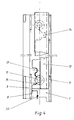
- the locking means 11 are spaced apart from one another over the length of the spreader table 1, as can be seen from FIG. Front and rear recesses 13, 14 in the section of the half-shell 12 which contacts the trough base of the spreader table 1 correspond to the locking means 11.
- the rear recesses 14 are intended for the half-shell 12 to be rotated by manual rotation and simultaneous axial displacement can be brought into the position "inserting or removing the spreader bar 15".
- first and second anti-rotation devices 19 in the form of resilient pins are arranged in the component 2 over the length of the spreader. These pins ensure that they engage in notches 21 or bores 20 in the half-shell and secure the half-shell against rotation and axial displacement.
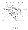
- Figure 2 shows a so-called intermediate position of the half-shell 12 in the spreader table 1.
- the half-shell 12 is rotated here so far in the direction of reducing the clear width of the fabric gap 16 that the locking means 11 are no longer in engagement with the rear recesses 14.
- the half-shell 12 can now be displaced axially within the spreader table 1, see arrow direction 22 in FIG. 4, until the front recesses 13 can be brought into engagement with the detents 11.
- the spreader table 1 is in the operating function tissue spreading and tissue clamping.
- the front recesses 13 of the half-shell 12 are now in a positive connection with the locking means 11, here for example with a centering piece 23 which is received by a countersunk screw 24 penetrating the base of the trough-shaped spreader table 1.
- the recesses 13, 14 are dimensioned such that the cylindrical section of the centering piece 23 can be accommodated with sufficient play.
- the spring-elastic anti-rotation device 19 is inserted into the bore 20 of the half-shell 12 and secures it against rotation. Between the inlet-side spreading element 8 of the spreading table 1 and the free end 12a of the half-shell 12 deflecting the fabric 7, there is now a fabric gap 16, the clear width of which is smaller than the diameter D of the spreading bar 15.
Landscapes
- Engineering & Computer Science (AREA)
- Textile Engineering (AREA)
- Looms (AREA)
- Auxiliary Weaving Apparatuses, Weavers' Tools, And Shuttles (AREA)
Claims (8)
- Templet transformable (1) en forme d'auge pour métiers à tisser à jets d'air, comprenant une saillie qui est orientée, dans la région du renvoi antérieur du tissu, vers le centre du canal d'insertion de trame d'un ros, et dont la face supérieure forme le prolongement de la surface d'appui du tissu dans le templet ; et un élément (8, 9) élargisseur du tissu (7), disposé tant à l'entrée du templet (1) qu'à la sortie dudit templet (1), caractérisé par le fait que, entre l'élément élargisseur (9) situé côté sortie et l'élément élargisseur (8) intégré dans le templet (1) dans la région du renvoi antérieur du tissu, un élément (12) de renvoi du tissu, de réalisation en demi-coquille, peut être engagé dans la partie en forme d'auge du templet (1) et peut être relié audit templet (1), par concordance de formes ou mécaniquement, de manière que puisse être formée, entre l'élément élargisseur (8) situé côté entrée et l'extrémité libre (12a) de l'élément de renvoi (12) du type demi-coquille, une fente (16) de passage du tissu, dont la largeur intérieure peut être modifiée en fonction du diamètre (D) d'une barre élargisseuse (15) supportée par le tissu (7).
- Templet selon la revendication 1, caractérisé par le fait que l'élément de renvoi (12) est agencé d'un seul tenant sur toute la longueur dudit templet (1).
- Templet selon les revendications 1 et 2, caractérisé par le fait que l'élément élargisseur antérieur (8) et l'extrémité libre (12a) de l'élément de renvoi (12) du type demi-coquille s'étendent parallèlement l'un à l'autre, et guident conjointement la barre élargisseuse (15) en contrecarrant la traction du tissu (7).
- Templet selon la revendication 1, caractérisé par le fait que l'élément de renvoi (12) du type demi-coquille présente, au voisinage de la liaison avec ledit templet (1), des évidements (13, 14) au moins antérieurs et postérieurs.
- Templet selon la revendication 4, caractérisé par le fait que les évidements (13, 14) sont ménagés à distance sur la longueur de la demi-coquille.
- Templet selon les revendications 4 et 5, caractérisé par le fait que les évidements (13, 14) sont en liaison avec des moyens (11) exerçant un effet d'arrêt et disposés rigidement dans ledit templet (1).
- Templet selon les revendications 4 et 5, caractérisé par le fait que les évidements (13, 14) sont en liaison avec des moyens (11) exerçant un effet d'arrêt et montés réglables dans ledit templet (1).
- Templet selon les revendications 1, 6 et 7, caractérisé par le fait que la liaison, entre ledit templet (1) et l'élément de renvoi (12), est réalisée à la manière d'une fermeture à baïonnette.
Applications Claiming Priority (2)
| Application Number | Priority Date | Filing Date | Title |
|---|---|---|---|
| DE4205514 | 1992-02-24 | ||
| DE4205514A DE4205514C2 (de) | 1992-02-24 | 1992-02-24 | Umrüstbarer muldenförmiger Breithaltertisch für Luftdüsenwebmaschinen |
Publications (2)
| Publication Number | Publication Date |
|---|---|
| EP0557724A1 EP0557724A1 (fr) | 1993-09-01 |
| EP0557724B1 true EP0557724B1 (fr) | 1995-12-20 |
Family
ID=6452382
Family Applications (1)
| Application Number | Title | Priority Date | Filing Date |
|---|---|---|---|
| EP93101035A Expired - Lifetime EP0557724B1 (fr) | 1992-02-24 | 1993-01-23 | Templet en forme d'auge transformable pour métiers à jet d'air |
Country Status (4)
| Country | Link |
|---|---|
| US (1) | US5305803A (fr) |
| EP (1) | EP0557724B1 (fr) |
| JP (1) | JP2857004B2 (fr) |
| DE (2) | DE4205514C2 (fr) |
Families Citing this family (3)
| Publication number | Priority date | Publication date | Assignee | Title |
|---|---|---|---|---|
| DE19713357A1 (de) * | 1996-12-23 | 1998-06-25 | Cramer Anton Gmbh Co Kg | Stabbreithalter für eine Webmaschine |
| IT1308631B1 (it) * | 1999-02-24 | 2002-01-09 | Vamatex Nuova Spa | Sostegno tessuto regolabile per telai di tessitura. |
| DE10211149A1 (de) * | 2002-03-14 | 2003-10-02 | Dornier Gmbh Lindauer | Breithalteeinrichtung |
Family Cites Families (10)
| Publication number | Priority date | Publication date | Assignee | Title |
|---|---|---|---|---|
| DE495300C (de) * | 1927-05-19 | 1930-04-05 | Axel Engelbrekt Norrman | Breithalter fuer Webstuehle |
| GB944231A (en) * | 1959-01-10 | 1963-12-11 | Wool Ind Res Association | Improvements relating to temples for weaving looms |
| CH457316A (de) * | 1966-05-27 | 1968-05-31 | Sulzer Ag | Webmaschine |
| NL7001832A (fr) * | 1969-02-11 | 1970-08-13 | ||
| CS160326B1 (fr) * | 1972-06-12 | 1975-03-28 | ||
| US3885600A (en) * | 1973-07-17 | 1975-05-27 | Jack G Altmann | Method and temple apparatus for guiding fabric lengths through textile weaving machines |
| NL7907123A (nl) * | 1979-09-25 | 1981-03-27 | Rueti Te Strake Bv | Breedhouder voor een weefmachine. |
| EP0292429A1 (fr) * | 1987-05-19 | 1988-11-23 | GebràDer Sulzer Aktiengesellschaft | Métier à tisser avec un dispositif pour l'étirage en largeur d'un tissu |
| DE3821725A1 (de) * | 1988-04-07 | 1989-10-26 | Dornier Gmbh Lindauer | Luftwebmaschine |
| DE3926525A1 (de) * | 1989-08-10 | 1991-02-14 | Dornier Gmbh Lindauer | Luftwebmaschine mit einem webblatt und im webblatt angeordnetem schusseintragskanal |
-
1992
- 1992-02-24 DE DE4205514A patent/DE4205514C2/de not_active Expired - Fee Related
-
1993
- 1993-01-23 DE DE59301185T patent/DE59301185D1/de not_active Expired - Fee Related
- 1993-01-23 EP EP93101035A patent/EP0557724B1/fr not_active Expired - Lifetime
- 1993-02-18 JP JP5028858A patent/JP2857004B2/ja not_active Expired - Lifetime
- 1993-02-22 US US08/047,555 patent/US5305803A/en not_active Expired - Fee Related
Also Published As
| Publication number | Publication date |
|---|---|
| DE59301185D1 (de) | 1996-02-01 |
| DE4205514C2 (de) | 1996-01-11 |
| DE4205514A1 (de) | 1993-08-26 |
| JPH05339852A (ja) | 1993-12-21 |
| US5305803A (en) | 1994-04-26 |
| JP2857004B2 (ja) | 1999-02-10 |
| EP0557724A1 (fr) | 1993-09-01 |
Similar Documents
| Publication | Publication Date | Title |
|---|---|---|
| DE2946180C3 (de) | Bandgewebe, Verfahren zu seiner Herstellung und Bandwebmaschine zur Durchführung des Verfahrens | |
| DE3781707T2 (de) | Verfahren und vorrichtung zum klemmen, festhalten und vorfuehren von schussfaeden bei greiferwebmaschinen. | |
| CH637707A5 (de) | Webblatt fuer eine duesenwebmaschine. | |
| DE3149900C2 (de) | Gewebtes Reißverschlußband und Vorrichtung zur Herstellung desselben | |
| EP0557724B1 (fr) | Templet en forme d'auge transformable pour métiers à jet d'air | |
| EP0716171B1 (fr) | Dispositif de tension et de détection de la trame pour métiers à tisser à jet d'air | |
| EP0707103B1 (fr) | Dispositif de tension de la chaíne pour metier à tisser | |
| DE69302210T2 (de) | Nehmergreifer für Webmaschinen | |
| EP0292429A1 (fr) | Métier à tisser avec un dispositif pour l'étirage en largeur d'un tissu | |
| EP0412294B1 (fr) | Machine à tisser pneumatique avec un dispositif d'élargissement sur le templet | |
| DE3421638C2 (de) | Webblatt mit integriertem Eintragkanal für eine schützenlose Webmaschine mit pneumatischem Schußfadeneintrag | |
| EP0822998A1 (fr) | Metier a tisser mecanique | |
| DD159184A1 (de) | Fassung zur halterung der wirknadeln an kettenwirkmaschinen | |
| EP0457718B1 (fr) | Pince de griffe pour métiers à tisser | |
| EP0786547A1 (fr) | Procédé et dispositif de rentrage d'un fil de trame | |
| EP0358748B1 (fr) | Guide-etoffe | |
| WO1988002038A1 (fr) | Tissu tricote en chaine et metier a tricoter a fil de trame pour produire le tissu tricote en chaine | |
| WO1999027171A1 (fr) | Buse de soufflage auxiliaire destinee a un metier a tisser a buse d'air | |
| EP0888470B1 (fr) | Templet pour metier a tisser | |
| DE102022200452B3 (de) | Schusseintragsvorrichtung für eine luftdüsenwebmaschine, düsenaufsatz sowie luftdüsenwebmaschine | |
| DE3034120A1 (de) | Eintragskanal fuer eine duesenwebmaschine | |
| CH659089A5 (de) | Webmaschine. | |
| CH674214A5 (fr) | ||
| DE60030609T2 (de) | Verstellbare Gewebestütze für Webmaschinen | |
| DE29720595U1 (de) | Hilfsblasdüse, insbesondere für eine Luftdüsenwebmaschine |
Legal Events
| Date | Code | Title | Description |
|---|---|---|---|
| PUAI | Public reference made under article 153(3) epc to a published international application that has entered the european phase |
Free format text: ORIGINAL CODE: 0009012 |
|
| AK | Designated contracting states |
Kind code of ref document: A1 Designated state(s): BE CH DE FR GB IT LI |
|
| 17P | Request for examination filed |
Effective date: 19931217 |
|
| 17Q | First examination report despatched |
Effective date: 19950524 |
|
| GRAA | (expected) grant |
Free format text: ORIGINAL CODE: 0009210 |
|
| AK | Designated contracting states |
Kind code of ref document: B1 Designated state(s): BE CH DE FR GB IT LI |
|
| REF | Corresponds to: |
Ref document number: 59301185 Country of ref document: DE Date of ref document: 19960201 |
|
| ITF | It: translation for a ep patent filed | ||
| REG | Reference to a national code |
Ref country code: CH Ref legal event code: NV Representative=s name: DIPL.-ING. ETH H. R. WERFFELI PATENTANWALT |
|
| ET | Fr: translation filed | ||
| GBT | Gb: translation of ep patent filed (gb section 77(6)(a)/1977) |
Effective date: 19960326 |
|
| PLBE | No opposition filed within time limit |
Free format text: ORIGINAL CODE: 0009261 |
|
| STAA | Information on the status of an ep patent application or granted ep patent |
Free format text: STATUS: NO OPPOSITION FILED WITHIN TIME LIMIT |
|
| 26N | No opposition filed | ||
| PGFP | Annual fee paid to national office [announced via postgrant information from national office to epo] |
Ref country code: CH Payment date: 19981221 Year of fee payment: 7 |
|
| PGFP | Annual fee paid to national office [announced via postgrant information from national office to epo] |
Ref country code: DE Payment date: 19981231 Year of fee payment: 7 |
|
| PGFP | Annual fee paid to national office [announced via postgrant information from national office to epo] |
Ref country code: BE Payment date: 19990111 Year of fee payment: 7 |
|
| PGFP | Annual fee paid to national office [announced via postgrant information from national office to epo] |
Ref country code: FR Payment date: 19990128 Year of fee payment: 7 |
|
| PGFP | Annual fee paid to national office [announced via postgrant information from national office to epo] |
Ref country code: GB Payment date: 19991221 Year of fee payment: 8 |
|
| PG25 | Lapsed in a contracting state [announced via postgrant information from national office to epo] |
Ref country code: LI Free format text: LAPSE BECAUSE OF NON-PAYMENT OF DUE FEES Effective date: 20000131 Ref country code: CH Free format text: LAPSE BECAUSE OF NON-PAYMENT OF DUE FEES Effective date: 20000131 Ref country code: BE Free format text: LAPSE BECAUSE OF NON-PAYMENT OF DUE FEES Effective date: 20000131 |
|
| BERE | Be: lapsed |
Owner name: LINDAUER DORNIER G.M.B.H. Effective date: 20000131 |
|
| REG | Reference to a national code |
Ref country code: CH Ref legal event code: PL |
|
| PG25 | Lapsed in a contracting state [announced via postgrant information from national office to epo] |
Ref country code: FR Free format text: LAPSE BECAUSE OF NON-PAYMENT OF DUE FEES Effective date: 20000929 |
|
| PG25 | Lapsed in a contracting state [announced via postgrant information from national office to epo] |
Ref country code: DE Free format text: LAPSE BECAUSE OF NON-PAYMENT OF DUE FEES Effective date: 20001101 |
|
| REG | Reference to a national code |
Ref country code: FR Ref legal event code: ST |
|
| PG25 | Lapsed in a contracting state [announced via postgrant information from national office to epo] |
Ref country code: GB Free format text: LAPSE BECAUSE OF NON-PAYMENT OF DUE FEES Effective date: 20010123 |
|
| GBPC | Gb: european patent ceased through non-payment of renewal fee |
Effective date: 20010123 |
|
| PG25 | Lapsed in a contracting state [announced via postgrant information from national office to epo] |
Ref country code: IT Free format text: LAPSE BECAUSE OF NON-PAYMENT OF DUE FEES;WARNING: LAPSES OF ITALIAN PATENTS WITH EFFECTIVE DATE BEFORE 2007 MAY HAVE OCCURRED AT ANY TIME BEFORE 2007. THE CORRECT EFFECTIVE DATE MAY BE DIFFERENT FROM THE ONE RECORDED. Effective date: 20050123 |