EP0557797A1 - Tête de lecture et d'écriture pour lecteur de disque magnétooptique - Google Patents
Tête de lecture et d'écriture pour lecteur de disque magnétooptique Download PDFInfo
- Publication number
- EP0557797A1 EP0557797A1 EP93102064A EP93102064A EP0557797A1 EP 0557797 A1 EP0557797 A1 EP 0557797A1 EP 93102064 A EP93102064 A EP 93102064A EP 93102064 A EP93102064 A EP 93102064A EP 0557797 A1 EP0557797 A1 EP 0557797A1
- Authority
- EP
- European Patent Office
- Prior art keywords
- head
- optical
- read
- disc
- heads
- Prior art date
- Legal status (The legal status is an assumption and is not a legal conclusion. Google has not performed a legal analysis and makes no representation as to the accuracy of the status listed.)
- Withdrawn
Links
- 230000003287 optical effect Effects 0.000 claims abstract description 42
- 239000010409 thin film Substances 0.000 description 3
- 230000007423 decrease Effects 0.000 description 2
- 230000001419 dependent effect Effects 0.000 description 2
- 238000010586 diagram Methods 0.000 description 2
- 238000000034 method Methods 0.000 description 2
- 229910052714 tellurium Inorganic materials 0.000 description 2
- PORWMNRCUJJQNO-UHFFFAOYSA-N tellurium atom Chemical compound [Te] PORWMNRCUJJQNO-UHFFFAOYSA-N 0.000 description 2
- GYHNNYVSQQEPJS-UHFFFAOYSA-N Gallium Chemical compound [Ga] GYHNNYVSQQEPJS-UHFFFAOYSA-N 0.000 description 1
- 230000005374 Kerr effect Effects 0.000 description 1
- 229910052771 Terbium Inorganic materials 0.000 description 1
- 238000005299 abrasion Methods 0.000 description 1
- 229910000808 amorphous metal alloy Inorganic materials 0.000 description 1
- 229910052797 bismuth Inorganic materials 0.000 description 1
- JCXGWMGPZLAOME-UHFFFAOYSA-N bismuth atom Chemical compound [Bi] JCXGWMGPZLAOME-UHFFFAOYSA-N 0.000 description 1
- 238000010276 construction Methods 0.000 description 1
- 230000003247 decreasing effect Effects 0.000 description 1
- 230000004907 flux Effects 0.000 description 1
- 229910052733 gallium Inorganic materials 0.000 description 1
- 230000001678 irradiating effect Effects 0.000 description 1
- 239000000463 material Substances 0.000 description 1
- 238000012986 modification Methods 0.000 description 1
- 230000004048 modification Effects 0.000 description 1
- 239000012860 organic pigment Substances 0.000 description 1
- 229910052761 rare earth metal Inorganic materials 0.000 description 1
- 150000002910 rare earth metals Chemical class 0.000 description 1
- 238000002310 reflectometry Methods 0.000 description 1
- 230000004044 response Effects 0.000 description 1
- OQRNKLRIQBVZHK-UHFFFAOYSA-N selanylideneantimony Chemical compound [Sb]=[Se] OQRNKLRIQBVZHK-UHFFFAOYSA-N 0.000 description 1
- 239000004065 semiconductor Substances 0.000 description 1
- GZCRRIHWUXGPOV-UHFFFAOYSA-N terbium atom Chemical compound [Tb] GZCRRIHWUXGPOV-UHFFFAOYSA-N 0.000 description 1
Images




Classifications
-
- G—PHYSICS
- G11—INFORMATION STORAGE
- G11B—INFORMATION STORAGE BASED ON RELATIVE MOVEMENT BETWEEN RECORD CARRIER AND TRANSDUCER
- G11B11/00—Recording on or reproducing from the same record carrier wherein for these two operations the methods are covered by different main groups of groups G11B3/00 - G11B7/00 or by different subgroups of group G11B9/00; Record carriers therefor
- G11B11/10—Recording on or reproducing from the same record carrier wherein for these two operations the methods are covered by different main groups of groups G11B3/00 - G11B7/00 or by different subgroups of group G11B9/00; Record carriers therefor using recording by magnetic means or other means for magnetisation or demagnetisation of a record carrier, e.g. light induced spin magnetisation; Demagnetisation by thermal or stress means in the presence or not of an orienting magnetic field
- G11B11/105—Recording on or reproducing from the same record carrier wherein for these two operations the methods are covered by different main groups of groups G11B3/00 - G11B7/00 or by different subgroups of group G11B9/00; Record carriers therefor using recording by magnetic means or other means for magnetisation or demagnetisation of a record carrier, e.g. light induced spin magnetisation; Demagnetisation by thermal or stress means in the presence or not of an orienting magnetic field using a beam of light or a magnetic field for recording by change of magnetisation and a beam of light for reproducing, i.e. magneto-optical, e.g. light-induced thermomagnetic recording, spin magnetisation recording, Kerr or Faraday effect reproducing
- G11B11/1055—Disposition or mounting of transducers relative to record carriers
- G11B11/10556—Disposition or mounting of transducers relative to record carriers with provision for moving or switching or masking the transducers in or out of their operative position
- G11B11/10573—Control of relative positioning of the magnetic and optical transducers, e.g. to move simultaneously
Definitions
- the present invention relates to a read-write head of a magneto-optical disc player, and more particularly to an improved head capable of quickly searching an area on an optical disc.
- optical discs such as a CD including a read only CD and a writable CD-R disc which is used as a ROM. Further, as a writable optical disc having a high recording density, a write once disc and a magneto-optical disc are provided. Information is recorded on the disc and reproduced with a laser beam. These discs are different from the CD in the material of the recording surface.
- the write once disc has a tellurium or bismuth recording surface on which the lasers burn pits for recording.
- the lasers are focused on a recording surface coated with a selenium antimony (Sb2Se3) thin film, or an oxide tellurium (TeOx) thin film, or a thin film of organic pigment, changing the reflectivity of the light.
- Sb2Se3 selenium antimony
- TeOx oxide tellurium
- the magneto-optical disc uses as the recording surface, an amorphous alloy made of rare earth metals such as gallium, terbium, and others.
- the recording surface of the disc is initially magnetized to form a magnetic field in a direction perpendicular to the surface.
- the laser heats a predetermined area of the disc to elevate the temperature above Curie temperature, which is about 150°C, thereby reversing the direction of the magnetic field.
- the laser is irradiated on the recording surface so that polarized wave front slightly rotates as a result of the Kerr effect. Thus only the polarized wave deflected by the rotation is read by a photodetector, thereby enabling to read the information.
- a conventional read-write head for recording information on a magneto-optical disc 1 and reading the information therefrom has a magneto-optical pickup 2 disposed under the disc 1 and a magnetic head 3 disposed above the disc.
- the pickup 2 and the magnetic head 3 are connected with each other by way of a connecting member 4.
- the connecting member 4 maintains the relative position between the pickup 2 and the magnetic head 3 constant, so that an area on the disc subjected to a magnetic field of the magnetic head 3 coincides with an area subjected to a laser beam 5 from the pickup 2.
- the read-write head In order to record information on the disc 1, the read-write head is radially moved to an appropriate position of the disc 1.
- the laser beam 5 from the pickup 2 heats the surface of the disc 1 to Curie temperature.
- a magnetic field caused by the magnetic head dependent on the information which is to be recorded reverses the direction of the magnetic field on the disc.
- the information can be written in an area which is already written by modulating the direction of the magnetic field.
- the read-write head Since the magnetic head 3 and the pickup 2 are held together by the connecting member 4, the read-write head is relatively heavy. Hence the head cannot be quickly moved in a radial direction of the disc, which prevents a rapid search of an area on the disc.
- the pickup 2 and the magnetic head 3 may be displaced from each other due to a deformation of the connecting member 4.
- the connecting member 4 since the connecting member 4 must have a large length in the radial direction of the disc, the player cannot be made much compact.
- An object of the present invention is to provide a read-write head for a disc player which may be reduced in weight, thereby enabling quick search of a determined area on a disc.
- read-write head of a magneto-optical disc player comprising an optical head having an optical pickup, and a magnetic head having an electromagnet.
- Each of the optical head and the magnetic head has driving means so as to be moved in a radial direction of the disc, and detecting means for detecting the radial position of the head.
- a control means is provided to control the driving means in accordance with the position of each of the optical head and the magnetic head detected by the detecting means.
- the detecting means detects the radial positions of the optical head and the magnetic head.
- the control means operates the driving means to move the heads to oppose each other.
- a read-write head comprises a magnetic head 16 and an optical head 17, positioned over and under a magneto-optical disc 14, respectively.
- the magnetic head 16 has a linear motor 7 which is slidably mounted on a guide rail 6 extending in a radial direction of the disc 14, and an electromagnet 18 mounted on the underside of the linear motor 7.
- a position sensor 8 On the upper side of the motor 7 is provided a position sensor 8 which detects the position of the magnetic head 16.
- the position sensor 8 detects a position on a linear scale 9 provided in parallel to the guide rail 6 by detecting a change in magnetic field thereof.
- the optical head 17 has a linear motor 11 slidably mounted on a guide rail 10 extending in the radial direction of the disc 14.
- An optical pickup 19 which applies a semiconductor laser beam 15 to the disc 14 is mounted on the linear motor 11.
- a linear scale 13 and a position sensor 12, which are similar to those of the magnetic head 16, are provided to detect the position of the optical head 17.
- a system for controlling the read-write head has a control unit 20 to which the output signal of the position sensors 8 and 12 are applied.
- the control unit 20 applies control signals to the linear motors 7 and 11 through drivers 7A and 11A, respectively, to operate them.
- the system further has a signal level sensor 19A which detects a level of a signal reproduced by the pickup 19 and applies a level signal to the control unit 20.
- the control unit 20 further operates the linear motors 7 and 11 in response to the level signal.
- the linear motors 7 and 11 are driven to move the magnetic head 16 and the optical head 17.
- the heads 16 and 17 stops when the position sensors 8 and 12 detect positions corresponding to a PCA (Power Calibration Area) which is the innermost of the disc.
- PCA Power Calibration Area
- the optical pickup 19 generates the laser beam 15 to raise the temperature of the PCA to the Curie temperature.
- the magnetic flux caused by the electromagnet 13 reverses the direction of the magnetic field on the recording surface of the disc 14, thereby recording a test signal in the PCA.
- the test signal is reproduced by irradiating a laser beam 15 so as to measure the level of the reproduced signal by the signal level sensor 19A.
- the magnetic head 16 is slightly moved to the right at a step 404.
- a test signal is again recorded and reproduced to detect the level thereof at a step 405. It is determined at a step 406 whether the level of the signal detected by the signal level sensor 19A increased. When the level increases, the program returns to the step 404, and the magnetic head 16 is further moved to the right.
- the magnetic head 16 is moved to the left at a step 407. Thereafter, the increase of the signal level is again checked at the steps 405 and 406 or at steps 408 and 409. In this manner, the magnetic head 16 is positioned at a location where the signal level becomes maximum, that is to say, where the electromagnet 18 most accurately opposes the optical pickup 19. Thus the optimum position of the magnetic head 16 is obtained.
- the position sensors 8 and 12 detect the positions of the magnetic head 16 and the optical head 17 on the scales 9 and 13, respectively, so that the relative position of the magnetic head 16 to the optical head 17 is obtained. The relative position is stored in a memory provided in the control unit 20.
- the optical head 17 is moved to a program area of the disc 14.
- the magnetic head 16 is also moved to the position where the relative position determined at the step 410 is maintained. Thereafter, the pickup 19 and the electromagnet 18 are actuated to write information on the disc 14.
- the recording operation is completed at a step 412.
- the electromagnet 18 is positioned to accurately oppose the optical pickup 19 without the connecting member. Therefore, it is possible to reduce the weight and size of the optical pickup head.
- Each of the position sensors 12 and 8 may be a photosensor adapted to detect the position based on modulation of light.
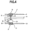
- the magnetic head 16 and the optical head 17 are provided with permanent magnets 21 and 22, respectively, instead of the position sensors 8 and 12.
- a magnetic force sensor 23 is mounted on one of the magnets 21 and 22 to detect magnetic force between the magnets 21 and 22.
- the optical pickup 19 reads information on the radial position of the disc 14, which is written in each area of the disc.
- the optical head 17 is moved to the PCA of the disc 14 in accordance with the position information stored in the PCA.
- the magnetic head 16 is moved to the same radial position as the optical head 17 by driving the linear motor 7 for a predetermined period.
- the optical head is fixed at a step 602.
- the magnetic head 16 is slightly moved to the right at a step 603. It is determined at a step 604 whether the output of the magnetic force sensor 23 increased. When the output increases, the program returns to the step 603, and the magnetic head 16 is further moved to the right.
- the magnetic head 16 when the magnetic force decreases, the magnetic head 16 is moved to the left at a step 605. Thereafter, the increase of the magnetic force is again checked at the step 604 or at a step 606.
- the magnetic head 16 is positioned at a location where the magnetic force between the magnets 21 and 22 becomes maximum, that is to say, where the electromagnet 18 most accurately opposes the optical pickup 19.
- the optimum relative position of the magnetic head 16 to the optical head 17 is determined at a step 607.
- the procedure for determining the relative position of the magnetic head 16 in accordance with the level of the reproduced signal is carried out at steps 608 to 615. These steps are identical to the steps 403 to 410 of Fig. 3 so that the explanation thereof is omitted. Namely, the relative position of the magnetic head 16 and the optical head is determined by the maximum level of the reproduced signal.
- the actual recording of information is performed while maintaining the relative positions of the heads constant, that is at relative positions determined at the step 615.
- the magnets 21 and 22 may be electromagnets.
- the electromagnets are de-energized when reproducing information, thereby decreasing the load exerted on the optical pickup 19.
- the present invention has been described relative to a magneto-optical disc player where information is recorded by magnetically modulating the magnetic field on the surface of the discs, the present invention may be applied to an optical disc player using an optical modulation system for recording.
- each of the upper and lower heads interposing the disc are moved to a desired position dependent on a position detected by the position sensor.
- the relative positions of the heads are not affected by deformation and abrasion of elements. Accordingly, information can be accurately recorded. Since the heads are not supported by an integral connecting member, each of the magnetic and optical heads can be independently and hence quickly moved, so that a determined area of the disc can be quickly searched. Moreover, a space taken up by the connecting member of the heads is no longer necessary so that the size of the disc player can be reduced.
Applications Claiming Priority (2)
| Application Number | Priority Date | Filing Date | Title |
|---|---|---|---|
| JP76021/92 | 1992-02-27 | ||
| JP07602192A JP3393655B2 (ja) | 1992-02-27 | 1992-02-27 | 光ディスクプレーヤ |
Publications (1)
| Publication Number | Publication Date |
|---|---|
| EP0557797A1 true EP0557797A1 (fr) | 1993-09-01 |
Family
ID=13593178
Family Applications (1)
| Application Number | Title | Priority Date | Filing Date |
|---|---|---|---|
| EP93102064A Withdrawn EP0557797A1 (fr) | 1992-02-27 | 1993-02-10 | Tête de lecture et d'écriture pour lecteur de disque magnétooptique |
Country Status (3)
| Country | Link |
|---|---|
| US (1) | US5371725A (fr) |
| EP (1) | EP0557797A1 (fr) |
| JP (1) | JP3393655B2 (fr) |
Families Citing this family (2)
| Publication number | Priority date | Publication date | Assignee | Title |
|---|---|---|---|---|
| DE19906983A1 (de) | 1999-02-19 | 2000-08-31 | Bayer Ag | Mischung aus Vinylcyclohexan basierenden Polymer/Copolymer und Stabilisatorsystem |
| US6970400B1 (en) * | 1999-09-27 | 2005-11-29 | Hitachi Maxell, Ltd. | Information recording medium with magnetic marks, recording and reproducing apparatus therefor, and head positioning method using detected magnetic leakage fields from the magnetic marks |
Citations (1)
| Publication number | Priority date | Publication date | Assignee | Title |
|---|---|---|---|---|
| EP0390259A1 (fr) * | 1989-03-28 | 1990-10-03 | Koninklijke Philips Electronics N.V. | Dispositif d'enregistrement et/ou de lecture d'un support d'information magnéto-optique |
Family Cites Families (9)
| Publication number | Priority date | Publication date | Assignee | Title |
|---|---|---|---|---|
| US4473750A (en) * | 1980-07-25 | 1984-09-25 | Hitachi, Ltd. | Three-dimensional shape measuring device |
| US4583212A (en) * | 1982-08-13 | 1986-04-15 | Ricoh Company, Ltd. | Record/playback head positioning device for optical disc apparatus |
| JPS59162668A (ja) * | 1983-03-08 | 1984-09-13 | Citizen Watch Co Ltd | リニアモ−タ内蔵キヤリツジ |
| US4868802A (en) * | 1986-07-28 | 1989-09-19 | Kabushiki Kaisha Toshiba | Magnetooptic recording and erasing head which performs biasing, tracking and focusing |
| JPH0739100Y2 (ja) * | 1988-04-04 | 1995-09-06 | 日立マクセル株式会社 | デイスクカートリツジ |
| US5239532A (en) * | 1989-03-28 | 1993-08-24 | U.S. Philips Corporation | Drive arrangement for the writing/reading heads of a magneto-optical disc apparatus |
| US5179544A (en) * | 1989-03-28 | 1993-01-12 | U.S. Philips Corporation | Control system for the magnetic head of a magneto-optical disc apparatus |
| JPH0340250A (ja) * | 1989-07-06 | 1991-02-21 | Matsushita Electric Ind Co Ltd | 光磁気ディスクおよび光磁気ディスク装置 |
| NL9001546A (nl) * | 1990-07-06 | 1992-02-03 | Philips Nv | Inrichting voor het inschrijven en/of uitlezen van een magneto-optische informatiedrager. |
-
1992
- 1992-02-27 JP JP07602192A patent/JP3393655B2/ja not_active Expired - Fee Related
- 1992-10-01 US US07/955,373 patent/US5371725A/en not_active Expired - Fee Related
-
1993
- 1993-02-10 EP EP93102064A patent/EP0557797A1/fr not_active Withdrawn
Patent Citations (1)
| Publication number | Priority date | Publication date | Assignee | Title |
|---|---|---|---|---|
| EP0390259A1 (fr) * | 1989-03-28 | 1990-10-03 | Koninklijke Philips Electronics N.V. | Dispositif d'enregistrement et/ou de lecture d'un support d'information magnéto-optique |
Non-Patent Citations (1)
| Title |
|---|
| PATENT ABSTRACTS OF JAPAN vol. 13, no. 322 (P-902)(3670) 20 July 1989 & JP-A-10 89 054 ( NEC HOME ELECTRON LTD ) 3 April 1989 * |
Also Published As
| Publication number | Publication date |
|---|---|
| JP3393655B2 (ja) | 2003-04-07 |
| US5371725A (en) | 1994-12-06 |
| JPH05242552A (ja) | 1993-09-21 |
Similar Documents
| Publication | Publication Date | Title |
|---|---|---|
| US5309419A (en) | M-O disk recording apparatus with light amount control based on multiple test performed on a test region at multiple disk rotational velocities | |
| EP0454038B1 (fr) | Méthode de contrôle pour faisceau d'enregistrement laser | |
| JPH0773529A (ja) | 光磁気記録方式および光磁気記録媒体 | |
| JPH056590A (ja) | 光磁気記録装置 | |
| US4868802A (en) | Magnetooptic recording and erasing head which performs biasing, tracking and focusing | |
| EP0488648B1 (fr) | Appareil d'enregistrement/reproduction d'informations optiques | |
| EP0569054B1 (fr) | Appareil d'enregistrement magnéto-optique | |
| US5371725A (en) | Position control system for a read-write head of a magneto-optical disc player having heads which move independently from each other | |
| US4982397A (en) | Apparatus for focusing a light beam onto an information memory medium having a data non-storage area | |
| US5465245A (en) | Optical pickup control system for an optical disc having recorded and non-recorded areas | |
| US5321686A (en) | Read-write head of an magneto-optical disc player with both heads magnetically coupled together | |
| US5361246A (en) | Optical information processing apparatus provided with means for detecting abnormality of focusing servo with a predetermined sensitivity | |
| JPH0757267A (ja) | 光ディスク装置 | |
| EP0339875B1 (fr) | Méthode et appareil pour l'initialisation d'une région entre les pistes d'un milieu d'enregistrement magnéto-optique | |
| US7362670B2 (en) | Optical disc drive | |
| JP2793294B2 (ja) | 情報記録再生装置 | |
| JP2856375B2 (ja) | 光磁気記録再生装置 | |
| EP1662500A1 (fr) | Procede et dispositif d'evaluation du traitement thermiqueapplique a un support d'enregistrement d'information magneto-optique | |
| JP3351472B2 (ja) | 光磁気ディスク記録再生装置 | |
| JPH07182668A (ja) | 光学的情報記録再生装置 | |
| JPH06302091A (ja) | 光学的記録装置 | |
| US20040196750A1 (en) | Method of braking control in rapid track seeking for an optical drive | |
| JPH09190669A (ja) | 情報再生装置及び光記録媒体の再生方法 | |
| JPH05266489A (ja) | 情報処理装置 | |
| JPS6355746A (ja) | 光磁気記録媒体の記録装置 |
Legal Events
| Date | Code | Title | Description |
|---|---|---|---|
| PUAI | Public reference made under article 153(3) epc to a published international application that has entered the european phase |
Free format text: ORIGINAL CODE: 0009012 |
|
| AK | Designated contracting states |
Kind code of ref document: A1 Designated state(s): DE FR GB |
|
| 17P | Request for examination filed |
Effective date: 19930728 |
|
| 17Q | First examination report despatched |
Effective date: 19950606 |
|
| GRAG | Despatch of communication of intention to grant |
Free format text: ORIGINAL CODE: EPIDOS AGRA |
|
| GRAG | Despatch of communication of intention to grant |
Free format text: ORIGINAL CODE: EPIDOS AGRA |
|
| GRAH | Despatch of communication of intention to grant a patent |
Free format text: ORIGINAL CODE: EPIDOS IGRA |
|
| GRAH | Despatch of communication of intention to grant a patent |
Free format text: ORIGINAL CODE: EPIDOS IGRA |
|
| STAA | Information on the status of an ep patent application or granted ep patent |
Free format text: STATUS: THE APPLICATION IS DEEMED TO BE WITHDRAWN |
|
| 18D | Application deemed to be withdrawn |
Effective date: 19990901 |