EP0557948A2 - Prädiktive Zwischenbildkodierungsvorrichtung mit Bewegungsausgleich - Google Patents
Prädiktive Zwischenbildkodierungsvorrichtung mit Bewegungsausgleich Download PDFInfo
- Publication number
- EP0557948A2 EP0557948A2 EP93102843A EP93102843A EP0557948A2 EP 0557948 A2 EP0557948 A2 EP 0557948A2 EP 93102843 A EP93102843 A EP 93102843A EP 93102843 A EP93102843 A EP 93102843A EP 0557948 A2 EP0557948 A2 EP 0557948A2
- Authority
- EP
- European Patent Office
- Prior art keywords
- picture
- motion
- storage circuit
- pictures
- predictive
- Prior art date
- Legal status (The legal status is an assumption and is not a legal conclusion. Google has not performed a legal analysis and makes no representation as to the accuracy of the status listed.)
- Granted
Links
Images







Classifications
-
- H—ELECTRICITY
- H04—ELECTRIC COMMUNICATION TECHNIQUE
- H04N—PICTORIAL COMMUNICATION, e.g. TELEVISION
- H04N5/00—Details of television systems
- H04N5/14—Picture signal circuitry for video frequency region
- H04N5/144—Movement detection
- H04N5/145—Movement estimation
-
- H—ELECTRICITY
- H04—ELECTRIC COMMUNICATION TECHNIQUE
- H04N—PICTORIAL COMMUNICATION, e.g. TELEVISION
- H04N19/00—Methods or arrangements for coding, decoding, compressing or decompressing digital video signals
- H04N19/42—Methods or arrangements for coding, decoding, compressing or decompressing digital video signals characterised by implementation details or hardware specially adapted for video compression or decompression, e.g. dedicated software implementation
- H04N19/43—Hardware specially adapted for motion estimation or compensation
- H04N19/433—Hardware specially adapted for motion estimation or compensation characterised by techniques for memory access
-
- H—ELECTRICITY
- H04—ELECTRIC COMMUNICATION TECHNIQUE
- H04N—PICTORIAL COMMUNICATION, e.g. TELEVISION
- H04N19/00—Methods or arrangements for coding, decoding, compressing or decompressing digital video signals
- H04N19/50—Methods or arrangements for coding, decoding, compressing or decompressing digital video signals using predictive coding
- H04N19/503—Methods or arrangements for coding, decoding, compressing or decompressing digital video signals using predictive coding involving temporal prediction
- H04N19/51—Motion estimation or motion compensation
-
- H—ELECTRICITY
- H04—ELECTRIC COMMUNICATION TECHNIQUE
- H04N—PICTORIAL COMMUNICATION, e.g. TELEVISION
- H04N19/00—Methods or arrangements for coding, decoding, compressing or decompressing digital video signals
- H04N19/50—Methods or arrangements for coding, decoding, compressing or decompressing digital video signals using predictive coding
- H04N19/503—Methods or arrangements for coding, decoding, compressing or decompressing digital video signals using predictive coding involving temporal prediction
- H04N19/51—Motion estimation or motion compensation
- H04N19/523—Motion estimation or motion compensation with sub-pixel accuracy
-
- H—ELECTRICITY
- H04—ELECTRIC COMMUNICATION TECHNIQUE
- H04N—PICTORIAL COMMUNICATION, e.g. TELEVISION
- H04N19/00—Methods or arrangements for coding, decoding, compressing or decompressing digital video signals
- H04N19/50—Methods or arrangements for coding, decoding, compressing or decompressing digital video signals using predictive coding
- H04N19/503—Methods or arrangements for coding, decoding, compressing or decompressing digital video signals using predictive coding involving temporal prediction
- H04N19/51—Motion estimation or motion compensation
- H04N19/533—Motion estimation using multistep search, e.g. two-dimensional [2D]-log search or one-at-a-time search [OTS]
-
- H—ELECTRICITY
- H04—ELECTRIC COMMUNICATION TECHNIQUE
- H04N—PICTORIAL COMMUNICATION, e.g. TELEVISION
- H04N19/00—Methods or arrangements for coding, decoding, compressing or decompressing digital video signals
- H04N19/50—Methods or arrangements for coding, decoding, compressing or decompressing digital video signals using predictive coding
- H04N19/503—Methods or arrangements for coding, decoding, compressing or decompressing digital video signals using predictive coding involving temporal prediction
- H04N19/51—Motion estimation or motion compensation
- H04N19/577—Motion compensation with bidirectional frame interpolation, i.e. using B-pictures
-
- H—ELECTRICITY
- H04—ELECTRIC COMMUNICATION TECHNIQUE
- H04N—PICTORIAL COMMUNICATION, e.g. TELEVISION
- H04N19/00—Methods or arrangements for coding, decoding, compressing or decompressing digital video signals
- H04N19/85—Methods or arrangements for coding, decoding, compressing or decompressing digital video signals using pre-processing or post-processing specially adapted for video compression
Definitions
- This invention relates to a coding apparatus for coding a motion picture, and more particularly to a video rate compressing and reproducing apparatus for storage media for use with a video mail system, a video tape recorder and so forth.
- High efficiency coding is applied to a video signal in order to store the video signal into a digital storage medium of a comparatively narrow band such as a compact disk (CD).
- a digital storage medium of a comparatively narrow band such as a compact disk (CD).
- MPEG Motion Picture Expert Group
- An investigation of the International Standardization Organization ISO-IEG JTC1/SC2/WG11 (hereinafter referred to as MPEG (Motion Picture Expert Group) as commonly called) is directed to coding systems for media of 1.5 Mbps.
- An outline of the investigated systems is described, for example, in Journal of Image electronics Society , Vol. 20, No. 4, pp.306-316. According to the document, it is forecast for hybrid coding including a combination of discrete cosine transform (DCT), quantization and variable length coding with motion compensated inter-frame prediction, to be adopted as an international standard.
- DCT discrete cosine transform
- While the basic scheme of the MPEG system is similar to that of the CCITT H.261 document which has been internationally standardized already for the object of an application to motion picture communications, it employs inter-frame prediction in which bidirectionally predictive coding (B-picture) into which backward prediction is included is incorporated in addition to intra-coding (I-picture) and predictive coding (P-picture). Further, enhancement of the coding efficiency is anticipated by raising the accuracy of motion vectors for use for motion compensation up to the accuracy of a half picture element. Since the amount of processing required for coding and the required memory capacity are increased remarkably comparing with those required for realization of an apparatus of the CCITT H261 standard in order to achieve the enhancement of the performance described above, much contrivance is required for realization of the coding apparatus.
- a chip set for image signal processing on the market is available from Graphics Communication Technologies (GCT). Functions of the individual chips of the chip set are described in Nikkei Electronics , July 25, 1990, pp.209-222. According to the description, the chip set provides individual processing functions such as motion vector detection, DCT, inverse DCT, quantization, inverse quantization, variable length coding and variable length decoding as chips for exclusive use so that a coding apparatus of the CCITT H.261 standard may be constituted from a combination of the processing functions.
- GCT Graphics Communication Technologies
- the function of reproducing a motion picture from a bit sequence obtained by coding is essentially required in addition to the real time coding function, and also the function of monitoring a picture being coded is required in order to supervise an influence of compression coding upon the picture quality.
- a motion picture coding apparatus for coding picture frames of an input motion picture signal as at least three kinds of inter-frame predictive pictures of an intra-coded picture, a predictive coded picture and a bidirectionally predictive coded picture, which comprises input picture re-arranging means for changing the order of the frames of the input motion pictures based on inter-frame prediction, a first storage circuit for storing therein decoded pictures decoded from intra-coded pictures and predictive coded pictures, first address generating means for controlling inputting and outputting of the first storage circuit, motion detecting means for detecting motion vectors between the decoded pictures stored in the first storage circuit and an output of the input picture re-arranging means, predictive signal generating means for generating an inter-frame predictive signal from the detected motion vectors and the decoded pictures stored in the first storage circuit and for producing and outputting a prediction difference signal representative of a difference of the inter-frame predictive signal from the output of the input picture rearranging means, quantizing means for quant
- the motion picture coding apparatus may further comprise a second storage circuit, an intra-coded picture or a predictive coded picture of the output of the input picture frame rearranging means being stored into the second storage circuit while the motion detecting means detects motion vectors between the input pictures stored in the second storage circuit and the output of the input picture re-arranging means, inputting and outputting of the second storage circuit being controlled by the first address generating means.
- the prediction signal generating means may simultaneously read out, from the first storage circuit, decoded data at the same address as the input picture data read out for last stage vector search from the second storage circuit by the motion detecting means and use the read out decoded data for generation of prediction.
- the motion picture coding apparatus may further comprise a third storage circuit for storing therein the output of the locally decoding means, second address generating means for controlling inputting and outputting of the third storage circuit, and an output port for outputting output data from the third storage circuit or the locally decoding means to the outside, the locally decoding means also generating a decoded picture of a bidirectionally predictive coded picture.
- a decoded picture of a bidirectionally predictive coded picture obtained from the locally decoding means may be outputted to the output port while a decoded picture of an intra-coded picture or a predictive coded picture is outputted to the output port after it is stored into the third storage circuit so as to arrange locally decoded pictures of the coded pictures back into those in order of reproduced frames and output them.
- the motion picture coding apparatus may further comprise variable length decoding means for decoding a variable length code word supplied from the outside by variable length coding, the second address generating means control reading out of predictive picture data from the third storage circuit using a motion vector decoded by the variable length decoding means while the locally decoding means produces a decoded picture from predictive picture data read out from the third storage circuit and the output of the variable length decoding means to realize a reproducing function.
- a decoded picture of a bidirectionally predictive coded picture obtained from the locally decoding means may be outputted to the output port while a decoded picture of an intra-coded picture or a predictive picture obtained from the locally decoding means is outputted, after it is stored into the third storage means, to the output so as to arrange the decoded pictures back to those in order of reproduced frames and output them.
- the order of frames of an input video signal is re-arranged prior to coding processing. This is because, in order to effect inter-frame prediction for object pictures for coding from the future, it is necessary to code/decode a frame, which is inputted later in time, precedently. If the input wherein the order of frames has been re-arranged is premised, then coding processing on the real time basis is possible by keeping the time required for coding of each frame within one frame period.
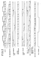
- FIG. 2 Such a procedure of processing as described above can be surveyed using FIG. 2.
- a frame train F i (..., F-1, F 0 ⁇ , F1, F2, ...) of input pictures is shown at an uppermost stage of FIG. 2.
- One of coding types of intra-coding (I-picture), predictive coding (P-picture) and bidirectionally predictive coding (B-picture) is allocated to each picture frame.
- the order of frames after the input order is re-arranged in accordance with the allocation is shown at a next lower stage.
- the order of re-arranged frames is (..., F 0 ⁇ , F ⁇ 2, F ⁇ 1 F3, F1, F2, F6, ...), and coding processing is applied in order of the frames.
- Reference characters FM and FM' denote frame memories having a capacity for two screens of the picture signal and are used for motion vector search and for storage of a locally decoded signal, respectively.
- the search memory (FM) is used to store therein input pictures corresponding to I- and/or P-pictures to detect motion vectors from a current input frame. For example, when the frame F ⁇ 2 or F ⁇ 1 is to be coded, since the frames F ⁇ 3 and F 0 ⁇ are stored in the search memory FM, they are used for motion vector search. Using the motion vectors thus obtained, locally decoded signals (F' ⁇ 3, F' 0 ⁇ ) stored in the memory FM' are read out to generate a predictive signal.
- an inter-frame predictive signal is generated using the locally decoded signal F' ⁇ 3 for forward prediction and using the locally decoded signal F' 0 ⁇ for backward prediction.
- the frame memories FM and FM' change over, in response to a signal TGL shown at a lowermost stage in FIG. 2, a top address to which the input signal and the locally decoded signal are to be stored, so that two I- and/or P-pictures coded last are stored there.
- a locally decoded signal may be used for detection of motion vectors in place of the input signal. In this instance, since motion vectors may be detected between contents of the frame memory FM' and a current input frame, the frame memory FM can be omitted.
- Coding processing in each frame period is performed for small blocks of N picture elements x N lines into which one picture is divided.
- N 16
- a standard image of, for example, 352 picture elements x 240 lines is divided into 330 blocks to code it.
- the present invention first adopts multistage search (the number of stages is hereinafter represented by K) for motion vector detection and then uses only subsampled signals for search at each stage to achieve reduction of the access frequency based on subsampling.
- the present invention employs the method wherein memory access for last stage search and access for predictive signal generation are performed simultaneously.
- a method of outputting a locally decoded signal to the outside in order to allow monitoring of a coded picture on the real time basis will be described. While the order in coding of the locally decoded signal is different from that of the input signal, the original order can be restored by storing two I- and/or P-pictures decoded last once into a memory. The change of order of frames to be displayed is necessary also as a reproducing function.
- a frame memory FM'' is prepared for both of reproduction and monitoring. A (locally) decoded signal is stored into FM'' as seen from FIG. 2, and it is placed back into the display order shown at a lower stage and then outputted.
- FIG. 2 an area for storing a B-picture therein is assured in the frame memory FM'' so that a B-picture may be stored once therein.
- any of I-, P-and B-pictures can be read out while changing it in the same scanning order.
- the B-picture area of frame memory FM'' can be omitted and only re-arrangement in order of frames is performed.
- the access frequency at the first stage is 0.25 * (N + n), and the search frequency (and generation of prediction) at the second stage is (N + 2)2. Accordingly, a total access is 1.25N2 + (4 + 0.25n)N + 4. Since this is an access frequency per block period, it can be seen that, if this is normalized with N2, then it is 1.25 + (4 + 0.25n) * (1/N) + 4/N2 times that of the original signal rate.
- a coding/decoding apparatus for storage media of a video rate and a coding processing technique wherein memories necessary for coding and decoding are disposed at substantially equal access frequencies are obtained. Consequently, development of a coding apparatus wherein various calculating functions are replaced with a VLSI of a higher performance to achieve reduction of the number of parts is allowed.
- the buffer memory size can be reduced comparing with the full search method, and this fact allows it suitable to obtain of a VLSI. Further, since only one address generating circuit must be provided, the number of address output pins for access to an external memory can be saved.
- interframe prediction since detection of a motion vector from an input signal can be realized only by addition of a memory chip (or by increase of the speed of the memory chip), a system suitable for an adopted system can be built up.
- Variable length coding and decoding processing, and generation of a monitoring address and generation of a reproduction address are functions which are used only upon coding and decoding, respectively. Accordingly, it becomes possible to adopt a processor form in development of a VLSI and change over functions of a single VLSI by replacement of a program. In this instance, since reproducing and monitoring functions can be realized by addition only of a memory chip when necessary, a system which is suitable for an apparatus configuration can be built up.
- the motion picture coding apparatus shown has a picture signal input port 17 and a bit sequence input/output port 18 and includes an input picture re-arranging circuit 1 for receiving input motion pictures and changing the order of frames of the input motion pictures based on inter-frame prediction, a storage circuit 2 for storing therein locally decoded pictures of coded I- and P-pictures, an address generating circuit 3, a motion detecting circuit 4, a predictive signal generating circuit 5, a quantizing circuit 6 for performing DCT and quantizing processing, a variable length coding circuit 7, and a local decoding circuit 8 for performing inverse quantization, inverse DCT and frame addition.
- the input frame re-arranging circuit 1 changes the order of frames of input motion pictures so that M-1 B-picture frames are placed between I- and/or P-picture frames.
- the input frame re-arranging circuit 1 includes a sequence control circuit 31 for allocating an I- or P-picture after every M-1 frames of input pictures and allocating B-pictures to frames between such adjacent I- and/or P-picture frames, and the sequence control circuit 31 outputs a signal of 3 bits after each frame period.
- the input frame re-arranging circuit 1 further includes a frame memory 32 into which data for M-1 frames can be stored, a pair of switches 33a and 33b, an OR gate 34, a toggle flip-flop 35 which reverses contents thereof in synchronism with a frame when the output of the OR gate 34 is "1", and a scan converting circuit 36 for converting a raster scan signal into a block scan signal.
- the output of the sequence control circuit 31 is, when represented in binary value, "100" for an I-picture, "010” for a P-picture and "001" for a B-picture with the MSB (most significant bit) thereof provided from the top terminal in FIG. 3.
- the thus re-arranged picture signal is subsequently converted into a block scan signal of 16 picture elements x 16 lines by the scan converting circuit 36 and outputted from the output port 38.
- the signal waveform TGL in FIG. 2 indicates an output waveform of the toggle flip-flop 35.
- the input motion picture signal after re-arranged by the input picture re-arranging circuit 1 in this manner is inputted to the motion detecting circuit 4, at which coding processing is subsequently performed for each block.
- the motion detecting circuit 4 at which coding processing is subsequently performed for each block.
- the motion detecting circuit 4 detects a motion vector from locally decoded signals stored in the storage circuit 2, and then, the predictive signal generating circuit 5 generates an optimum predictive signal based on the detected motion vector using data of the storage circuit 2. Then, the predictive signal thus generated is inputted to the locally decoding circuit 8, and a predictive difference signal of the predictive signal from the input signal is outputted from the predictive signal generating circuit 5 to the quantizing circuit 6.
- the configuration and operation of the address generating circuit 3, the motion detecting circuit 4 and the predictive signal generating circuit 5 will be hereinafter described in detail.
- the predictive difference signal is processed for discrete cosine transform and quantization into a conversion coefficient by the quantizing circuit and is then coded into a final bit sequence together with coded mode information of the motion vector and so forth not shown by the variable length coding circuit 7, whereafter it outputted to the outside by way of the output port 18. Meanwhile, inverse operation to that of the quantizing circuit 6 is performed for the output of the quantizing circuit 6 by the locally decoding circuit 8.
- the locally decoding circuit 8 thus generates a locally decoded signal of an I- or P-picture from the thus obtained signal from the quantizing circuit 6 and the predictive signal inputted thereto from the predictive signal generating circuit 5 and stores the thus generated locally decoded signal into the storage circuit 2.
- the quantizing circuit 6, the variable length coding circuit 7 and the locally decoding circuit 8 can be constructed using an LSI already on the market for commercial use such as, for example, a chip set supplied from the GCT described hereinabove.
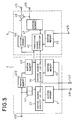
- the motion picture coding apparatus of the present embodiment is a modification to and has the same configuration as the motion picture coding apparatus of the preceding embodiment shown in FIG. 1 except that it additionally includes another a storage circuit 9 into which only an I- or P-picture of the output of the input picture re-arranging circuit 1 is stored.
- a picture signal stored in the storage circuit 9 is inputted to the motion detecting circuit 4.
- the same address as the address supplied from the address generating circuit 3 to the storage circuit 2 is used for accessing to the storage circuit 9.
- the motion detecting circuit 4 employs a motion vector search method which involves two-stage vector search in which it searches, at the first stage, within the range of 32 picture elements x 32 lines with the accuracy of two picture elements and then performs, at the second stage, motion vector search with the accuracy of one picture element and 0.5 picture elements, to detect motion vectors with the accuracy of 0.5 picture elements within the range of ⁇ 9 data in the horizontal and vertical directions with regard to forward and backward directions.
- a manner of search at the first stage is illustrated in FIG. 6(a), and a manner of search at the second stage is illustrated in FIG. 6(b).
- the motion detecting circuit 4 has an input port 410 from the input picture re-arranging circuit 1, a motion vector output port 417 to the address generating circuit 3, and an input port 418, to which, when the configuration of FIG. 1 is employed, an output of the storage circuit 2 is supplied, but when the configuration of FIG. 4 is employed, an output of the storage circuit 9 is supplied.
- the motion detecting circuit 4 includes a pair of buffer memories 41 and 43 for vector search for the first and second stages, respectively, a pair of vector search circuits 42 and 44 for the first and second stages, respectively, and three buffer memories 411, 412 and 413 for an input signal from the input port 410.
- the predictive signal generating circuit 5 has a pair of output ports 415 and 416 to the quantizing circuit 6 and the locally decoding circuit 8, respectively, and a data input port 419 from the storage circuit 2, and includes a buffer memory 45 for a locally decoded signal, a predictive signal generating unit 46 connected to the vector search circuit 44 and the buffer memory 413, a predictive signal storage buffer memory 47, a subtractor 48 for subtracting a predictive signal from an input picture signal to obtain a predictive difference signal, and a buffer memory 414 connected to the buffer memory 413.
- the first stage search 1/2 subsampling is performed in the directions of columns and rows from a search window of 32 picture elements x 32 columns, and 16 x 16 data are fetched into the search buffer 41 of FIG. 5. Meanwhile, also an input signal is subsampled for data (16 x 16) of one block in a grid-like pattern to obtain 8 x 8 data, which are stored into the buffer memory 411. The subsampling pattern then is indicated by round marks in FIG. 6(a).
- the vector search circuit 42 searches within the range of ⁇ 4 data (corresponding to ⁇ 8 data on the original picture signal) in each of the horizontal and vertical directions. The trial vector number then is 81 with 9 vectors ( ⁇ 4 data) in each of the horizontal and vertical directions.
- the data which must necessarily be stored newly into the buffer memory 41 then are those within the range of 8 x 16 data indicated by slanting lines in FIG. 6(a) (corresponding to 16 picture elements x 32 lines on the original picture signal).
- the first stage motion vector search circuit 42 accumulates absolute values of differences in units of picture elements for the individual trial vectors and detects its minimum value to obtain an optimum vector.
- Such calculating processing can be realized, for example, using an LSI ST3220 for motion vector detection manufactured by INMOS. An outline of operation of the LSI ST3220 is described in Video Information Magazine , June 1931, pp.83-89. According to the description, in order to detect an optimum vector from within 256 trial vectors within the range of -8 to +7 picture elements and -8 to +7 lines, 256 processor elements (PEs) of the same number as the trial vector number are caused to operate in parallel. In order to realize the vector search circuit 42 of the construction, search at the first stage can be realized if only 81 processor elements of the total of 256 processor elements are used for operation.
- PEs processor elements
- the second stage motion vector search circuit 44 includes a line memory 61 for realizing a delay for one line (18 picture elements), three adders 62a, 62b and 62c, three multipliers 64a, 64b and 64c for multiplication of 1/2, 1/2 and 1/4, respectively, and a pair of delay units 65a and 65b.
- An interpolating unit 60 is constituted from the components 61, 62a to 62c, 64a to 64c and 65a and 5b.
- the motion vector search circuit 44 further includes four vector circuits 63a, 63b, 63c and 63e and a minimum value detecting circuit 66, and has a pair of input ports 67 and 68 to which input block signals are supplied from the buffer memories 413 and 43, respectively, of FIG. 5 and search area data of the second stage are supplied, and an output port 69 for outputting detected motion vectors to the predictive signal generating circuit 5.
- Data of 18 x 18 picture elements fetched into the buffer memory 43 are read out in order of block scan to the input port 68.
- a train of data of integral number picture elements (o), horizontal direction 0.5 picture element interpolation (h), vertical direction 0.5 picture element interpolation (v) and horizontal/vertical 0.5 picture element interpolation (hv) corresponding to the arrangement of FIG. 6(b) is outputted from the interpolating unit 60.
- a processor element (PE) similar to the LSI ST3220 described hereinabove is connected to each interpolation signal by a number corresponding to trial vectors.
- the motion vector detecting circuit for the second stage can be constructed.
- An optimum motion vector (search range of ⁇ 1 data) with the accuracy of 0.5 picture elements is determined by the minimum value detecting circuit 66 and outputted to the predictive signal generating circuit 5 by way of the output port 69 in such a manner as described above.
- the predictive signal generating circuit 46 determines an optimum predictive method between the predictive signal and the input block signal to the buffer memory 414 to find out an inter-frame predictive signal and stores it into the predictive signal storing buffer memory 47.
- the inter-frame predictive signal stored in the buffer memory 47 is outputted to the locally decoding circuit 8 by way of the output port 416.
- the input signal delayed by interval of times required for vector search and predictive signal generation by the buffer memories 412, 413 and 414 is converted into a difference signal from the optimum inter-frame predictive signal stored in the buffer memory 47 by the subtractor 48 and is outputted to the quantizing circuit 6 by way of the output port 415.
- FIG. 8 shows operation timings of the circuits shown in FIG. 5.
- a block of 16 x 16 picture elements of each frame are successively processed by pipeline processing for a block period of three stages including search at the first stage, search at the second stage and generation of a predictive signal.
- pipeline processing for a block period of three stages including search at the first stage, search at the second stage and generation of a predictive signal.
- search at the first stage search at the second stage
- generation of a predictive signal For example, in the case of 352 x 240 motion pictures of 30 frames/second, real time processing is assured if the coding period of one block is within about 100 microseconds.
- Forward and backward vector detection is performed in a time division condition dividing one block period to one half.
- data necessary for forward prediction are fetched in the front half of a block period and data necessary for backward prediction are fetched in the rear half of the block period so that data necessary for vector detection and predictive signal generation may be prepared in the buffer memories 41, 43 and 45 of FIG. 5.
- the address generating circuit 3 is controlled for each of I-, P-and B-pictures by control signals x and y shown at lower stages of FIG. 8 so that data inputting and outputting timings to and from the storage circuit 2 and the storage circuit 9 are determined.
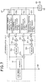
- the address generating circuit 3 has an input port 910 to which a motion vector detected by the first stage vector search circuit 42 is supplied, and an output port 911 for outputting an address to the storage circuit 2 and the storage circuit 9 therefrom.
- the address generating circuit 3 includes a block base address generating circuit 90 for a coded block, a block base address generating circuit 91a for writing into the storage circuit 9, a block base address generating circuit 91b for writing into the storage circuit 2, a pair of 92a and 92b, a delay unit 93 for outputting a block base address delayed by one block period, three block scan address generating circuits 94, 95 and 96, four selectors 97a, 97b, 97c and 97d, and a gate circuit 99.
- the address generating circuit 3 further includes a frame base address generating circuit 98 which outputs two base addresses of a picture signal alternately to two output terminals in response to the TGL signal of FIG. 2.
- Those addresses are outputted in a time division multiplexed condition in a time slot which depends upon a combination of the control signals x, y and z shown at the lower stage of FIG. 8 and I, P and B identification signals generated by the sequence control circuit 31 (FIG. 3).
- an output of the selector 97b is selected as the output of the selector 97c irrespective of the control signal x.
- the selector 97b selects a data read address for first stage vector search when the control signal y is at a high level, but selects a data read address for second stage vector search when the control signal y is at a low level.
- the selector 97c selects an output of the block scan address generating circuit 96 in the rear half of a block period while an I- or P-picture is coded.
- the selector 97a selects an output of the write block base address generating circuit 91a for the storage circuit 9 to the block scan address generating circuit 96 when the control signal z is at a high level, but selects an output of the write block base address generating circuit 91b for the storage circuit 2 to the block scan address generating circuit 96 when the control signal z is at a low level. In this manner, the period between P- and/or an I-pictures is used for writing of data into a search memory in the rear half of a block period.
- FIGS. 10(a) and 10(b) Memory access interleaves for each block period are collectively shown in FIGS. 10(a) and 10(b).
- FIG. 10(a) illustrates time slot allocation when the configuration of FIG. 1 is employed
- FIG. 10(b) illustrates time slot allocation when the configuration of FIG. 4 is employed.
- one cycle is required to write or read out data of one picture element.
- reference characters r1f and r1b denote read-out of data necessary for first stage vector search
- r2f and r2b denote read-out of data necessary for second stage vector search
- reference character w2 denotes writing of data into the storage circuit 2
- memory access of 256 cycles per block period corresponds to the signal rate of the input video signal. From FIGS. 10(a) and 10(b), it can be seen that, since the access frequency is lower than 1,024 cycles per block period with any of I-, P- and B-pictures, with the circuit configuration of the present embodiment, the access to the storage circuits 2 and 9 remains within four times that of the original signal.
- a low-pass filter is provided at a stage preceding to subsampling in order to achieve enhancement of the accuracy in vector search by subsampling.
- a low pass filter is applied to writing into the storage circuit 9 or the storage circuit 2 to which the motion vector detecting circuit refers so as to effect subsampling to 1/4.
- the storage circuit 2 and the storage circuit 9 are formed as separate memories, if a high speed memory chip is adopted, then contents of the storage circuit 2 and the storage circuit 9 can be mapped in separate address spaces in the single storage circuit.
- search at the first to the K-1th stages can be realized using contents of the buffer memory 41 if only the first stage vector search circuit 42 is modified.
- the memory access necessary for transmission of data to the buffer memory 41 and the capacity of the buffer memory 41 are reduced to one fourth that of the case wherein search in the same search range is performed with the accuracy of one picture element.
- the motion picture coding apparatus of the present embodiment performs coding processing on the real time basis and simultaneously outputs a locally decoded signal to a monitor screen to provide supervising means for a compressed coded picture.
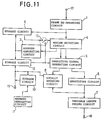
- the motion picture coding apparatus is a modification to and different from the motion picture coding apparatus of the second embodiment shown in FIG. 4 in that it additionally has a monitor/reproduction signal output port 19 and additionally includes a monitoring/reproducing storage circuit 10, an address generating circuit 11, and a switch 13.
- the motion vector detecting circuit 4 can selectively use, for vector search, an input signal stored in the storage circuit 9 and a locally decoded signal stored in the storage circuit 2.
- the locally decoding circuit 8 generates locally a decoded signal not only of an i- or P-pictures but also of a B-picture. While a locally decoded I- or P-picture is stored into the storage circuit 2 similarly as in the motion picture coding apparatus of the first and second embodiments described hereinabove, it is simultaneously stored also into the storage circuit 10.
- the locally decoded signal of an I-or P-picture written in the storage circuit 10 is outputted at a delayed timing shown at a lower stage of FIG. 2 so that the order of frames thereof is put back into that of the reproduced signal and the locally decoded signal of the order is outputted to the output port 19.
- the scanning order in a frame is that of block scanning of 16 x 16.
- read-out from the storage circuit 10 is performed in order of raster scanning.
- I- or P-picture since it is stored once into the storage circuit 10, such read-out can be realized by generation of a read address, but scan change for a B-picture must be assured newly in the storage circuit 10. Operation of the address generating circuit 11 necessary for such frame order change or intra-frame scan change will be hereinafter described.
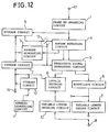
- FIG. 12 there is shown a motion picture coding apparatus according to a fourth preferred embodiment of the present invention.
- the present embodiment provides means for reproducing an already coded bit sequence to confirm a coded picture or for searching an editing point during edition.
- the motion picture coding apparatus of the present embodiment is a modification to and different from the motion picture coding apparatus of FIG. 1 in that it additionally includes a variable length decoding circuit 12.
- those functions of the motion picture coding apparatus of the present embodiment which are necessary for coding that is, the input picture re-arranging circuit 1, the motion detecting circuit 4, the predictive signal generating circuit 5, the quantizing circuit 6 and the variable length coding circuit 7, stop their operation.
- variable length decoding circuit 12 codes, by variable length coding, a coded bit sequence supplied from the outside to the bit sequence input/output port 18. Motion vectors reproduced by the variable length decoding circuit 12 are outputted to the address generating circuit 11. Signals read out from the variable length decoding circuit 12 and the storage circuit 10 by the address generating circuit 11 are inputted to the locally decoding circuit 8.
- the variable length decoding circuit 12 can be realized with such an LSI as in the chip set described on the pages of the prior art.
- the locally decoding circuit 8 reproduces a predictive signal from a decoded picture read out from the storage circuit 10 to obtain a reproduced signal by frame adding processing to a predictive error signal inputted from the variable length decoding circuit 12.
- the predictive signal for which motion vectors with the accuracy of 0.5 picture elements are used must necessarily be reproduced by calculation in the locally decoding circuit 8 from the range of 17 x 17 data for each of forward and backward directions.
- An I-or P-picture reproduced by the locally decoding circuit 8 is stored into the storage circuit 10 and is used for generation of an inter-frame predictive signal of a P-picture and a B-picture which is decoded later.
- the method of outputting a reproduced signal from the output port 19 is the same as that for a monitor output of the motion picture coding apparatus of the third embodiment described above.
- FIG. 13 Details of the address generating circuit 11 which is used commonly with the motion picture coding apparatus of the third and fourth embodiments of the present invention are shown in FIG. 13.
- the address generating circuit 11 has an address output port 133a, and an input port 133b to which, only upon when the construction of FIG. 12 is employed, an integral number portion of a motion vector decoded by the variable length decoding circuit 12 is inputted.
- the address generating circuit 11 includes a block base address generating circuit 130 for outputting a base address of a block to be decoded by the locally decoding circuit 8, a delay unit 131 for delaying the block base address, a pair of adders 132a and 132b, a read-out raster scan address generating circuit 134, a write block scan address generating circuit 135, a decoding block scan address generating circuit 136 for generating a block scan address of 17 x 17 data, four selectors 137a, 137b, 137c and 137d, a frame base address generating circuit 138, a gate circuit 139, and an address output port 133a.
- the frame base address generating circuit 138 outputs two base addresses for a picture signal alternately to two output terminals in response to the TGL signal of FIG. 2.
- the write block scan address generating circuit 135 generates a decoded signal write address using an address of an output of the block base counter 130, which is delayed by a reproduction processing delay amount (one block period) by the locally decoding circuit 8, as the starting point. Further, the read-out raster scan address generating circuit 134 generates an address of data to be read out from the storage circuit 10 to the output port 19.
- the decoding block scan address generating circuit 136 is used only when a reproduced signal is to be obtained from a bit sequence.
- the decoding block scan address generating circuit 136 generates an address to read out the range of 17 x 17 data necessary for reproduction of a predictive signal using an address, which is obtained by addition by the adder 132a of an integral number portion of a decoded motion vector inputted from the input port 133a to an output of the block base counter 130, as the starting point.
- the selector 137a selects, in response to a control signal x, an output of the read-out raster scan address generating circuit 134 in the former half of a block period but selects a write address generated by the block scan address generating circuit 135 in the latter half of the block period. Meanwhile, the selector 137b selects an output of the block scan address generating circuit 136 when a control signal z is at a high level, but selects an output of the selector 137a when the control signal z is at a low level. In this manner, outputs of the three kinds of address generating circuits are interleaved for a block period and outputted to the output of the selector 137b.
- an appropriate frame base address is selected by the selectors 137c and 137d under the control of the TGL signal and the gate circuit 139 and is converted into an actual address on a memory by the adder 132b.
- a base address "B-base" of a scan change region of a B-picture is selected by the selector 137c.
- a frame base address for forward prediction and another frame base address for backward prediction are switched in the former half and the latter half of a block period by the selector 137d and supplied to the adder 132b.
- Time slot allocation of an output address of the address generating circuit 11 within a block period is shown in FIG. 14.
- a time slot used upon reproduction is shown.
- three kinds of memory access are interleaved in the block period and outputted to the storage circuit 10.
- reference character ro denotes read-out of data to the output port 19
- reference characters rf and rb denote read-out of data to the locally decoding circuit 8 necessary upon reproduction
- reference character w denotes write of data into the storage circuit 10.
- motion vector detection can be realized within the memory access range to each storage circuit which is, to the utmost, four times or more the original picture signal rate.
Landscapes
- Engineering & Computer Science (AREA)
- Multimedia (AREA)
- Signal Processing (AREA)
- Compression Or Coding Systems Of Tv Signals (AREA)
- Television Signal Processing For Recording (AREA)
- Color Television Systems (AREA)
Applications Claiming Priority (3)
| Application Number | Priority Date | Filing Date | Title |
|---|---|---|---|
| JP7554492 | 1992-02-25 | ||
| JP7554492A JPH05236466A (ja) | 1992-02-25 | 1992-02-25 | 動き補償フレーム間予測画像符号化装置及び方法 |
| JP75544/92 | 1992-02-25 |
Publications (3)
| Publication Number | Publication Date |
|---|---|
| EP0557948A2 true EP0557948A2 (de) | 1993-09-01 |
| EP0557948A3 EP0557948A3 (en) | 1994-07-27 |
| EP0557948B1 EP0557948B1 (de) | 2001-05-09 |
Family
ID=13579254
Family Applications (1)
| Application Number | Title | Priority Date | Filing Date |
|---|---|---|---|
| EP19930102843 Expired - Lifetime EP0557948B1 (de) | 1992-02-25 | 1993-02-24 | Prädiktive Zwischenbildkodierungsvorrichtung mit Bewegungsausgleich |
Country Status (4)
| Country | Link |
|---|---|
| US (1) | US5473378A (de) |
| EP (1) | EP0557948B1 (de) |
| JP (1) | JPH05236466A (de) |
| DE (1) | DE69330191T2 (de) |
Cited By (13)
| Publication number | Priority date | Publication date | Assignee | Title |
|---|---|---|---|---|
| WO1995004432A1 (en) * | 1993-07-30 | 1995-02-09 | British Telecommunications Plc | Coding image data |
| EP0613299A3 (de) * | 1993-02-25 | 1995-02-15 | Ind Tech Res Inst | Doppelbusarchitektur für Bewegungskompensation. |
| EP0644697A3 (en) * | 1993-09-17 | 1995-04-26 | Daewoo Electronics Co Ltd | Method for half-pixel motion compensation in image decoding. |
| WO1995025404A1 (fr) * | 1994-03-16 | 1995-09-21 | France Telecom | Procede et dispositif d'estimation de mouvement entre images de television d'une sequence d'images |
| EP0674444A1 (de) * | 1994-03-24 | 1995-09-27 | STMicroelectronics S.A. | Filter für Matrix von Pixeln |
| US5557320A (en) * | 1995-01-31 | 1996-09-17 | Krebs; Mark | Video mail delivery system |
| EP0644698A3 (de) * | 1993-09-14 | 1997-03-05 | Gold Star Co | B-Bild Verarbeitungsvorrichtung mit halbpixel Bewegungskompensation für einen Bildkodierer. |
| EP0735769A3 (de) * | 1995-03-27 | 1997-11-05 | International Business Machines Corporation | Halbpel-Bewegungsschätzungsmethode für B-Bilder |
| EP0717410A3 (de) * | 1994-12-12 | 1998-03-18 | Sony Corporation | Vorrichtung und Verfahren zur Kodierung und/oder Dekodierung von Daten |
| EP0689358A3 (de) * | 1994-06-13 | 1998-04-29 | Lg Electronics Inc. | Adressenerzeugungsschaltung für Bildbewegungskompensation |
| EP0687111A3 (de) * | 1994-06-06 | 1998-12-16 | SICAN, GESELLSCHAFT FÜR SILIZIUM-ANWENDUNGEN UND CAD/CAT NIEDERSACHSEN mbH | Verfahren zur Codierung/Decodierung eines Datenstroms |
| EP0767588A3 (de) * | 1995-10-04 | 1999-10-20 | Matsushita Electric Industrial Co., Ltd. | Verfahren und Vorrichtung zur Berechnung eines Pixelblocks mit einem oder zwei Prädiktionsblöcken |
| CN1925625B (zh) * | 1994-09-26 | 2010-06-16 | 三菱电机株式会社 | 数字视频信号的记录和重放设备及其记录和重放的方法 |
Families Citing this family (32)
| Publication number | Priority date | Publication date | Assignee | Title |
|---|---|---|---|---|
| JP3275423B2 (ja) * | 1993-03-04 | 2002-04-15 | キヤノン株式会社 | 記録装置 |
| GB9308952D0 (en) * | 1993-04-30 | 1993-06-16 | Philips Electronics Uk Ltd | Tracking objects in video sequences |
| DE69422960T2 (de) * | 1993-12-01 | 2000-06-15 | Matsushita Electric Industrial Co., Ltd. | Verfahren und Vorrichtung zum Editieren oder zur Mischung von komprimierten Bildern |
| DE4342305A1 (de) * | 1993-12-11 | 1995-06-29 | Thomson Brandt Gmbh | Verfahren zur hierarchischen Bewegungsschätzung in einem Fernsehsignal |
| JP2858631B2 (ja) * | 1994-06-29 | 1999-02-17 | 日本ビクター株式会社 | 画像データ編集装置及び画像データ復号装置 |
| JP2970417B2 (ja) * | 1994-08-22 | 1999-11-02 | 日本電気株式会社 | 動画像符号化方式 |
| KR0178231B1 (ko) * | 1995-08-10 | 1999-05-01 | 배순훈 | 계층적인 움직임 추정 기법을 이용하는 움직임 벡터 검출 방법 및 장치 |
| JP2738325B2 (ja) * | 1995-01-24 | 1998-04-08 | 日本電気株式会社 | 動き補償フレーム間予測装置 |
| US5734677A (en) * | 1995-03-15 | 1998-03-31 | The Chinese University Of Hong Kong | Method for compression of loss-tolerant video image data from multiple sources |
| JP3535297B2 (ja) | 1996-01-26 | 2004-06-07 | ローム株式会社 | 画像データ復号方法およびこの方法を用いた画像データ復号装置 |
| US8625665B2 (en) * | 1996-09-20 | 2014-01-07 | At&T Intellectual Property Ii, L.P. | Video coder providing implicit coefficient prediction and scan adaptation for image coding and intra coding of video |
| US6341144B1 (en) * | 1996-09-20 | 2002-01-22 | At&T Corp. | Video coder providing implicit coefficient prediction and scan adaptation for image coding and intra coding of video |
| EP1689191A3 (de) * | 1996-11-07 | 2008-12-10 | Panasonic Corporation | Bildcoder und -decoder |
| US6208655B1 (en) | 1996-11-27 | 2001-03-27 | Sony Europa, B.V., | Method and apparatus for serving data |
| WO1998042134A1 (fr) * | 1997-03-17 | 1998-09-24 | Mitsubishi Denki Kabushiki Kaisha | Codeur et decodeur d'image, methode de codage et de decodage d'image, et systeme de codage/decodage d'image |
| EP0917363A1 (de) * | 1997-11-17 | 1999-05-19 | STMicroelectronics S.r.l. | Algorithmus zur Bewegungsschätzung und Architektur des Systems |
| US6313767B1 (en) * | 1999-02-19 | 2001-11-06 | Canon Kabushiki Kaisha | Decoding apparatus and method |
| US20020110094A1 (en) * | 2001-02-13 | 2002-08-15 | Reddy Naveen S. | Spot beam hopping packet scheduler system |
| US6868123B2 (en) * | 2001-12-07 | 2005-03-15 | Motorola, Inc. | Programmable motion estimation module with vector array unit |
| US6987807B2 (en) * | 2002-04-19 | 2006-01-17 | Seiko Epson Corporation | Frame compression using differential codes and an escape code |
| JP4841101B2 (ja) | 2002-12-02 | 2011-12-21 | ソニー株式会社 | 動き予測補償方法及び動き予測補償装置 |
| KR100892471B1 (ko) * | 2004-07-13 | 2009-04-10 | 파나소닉 주식회사 | 움직임 검출 장치 |
| US20080031335A1 (en) * | 2004-07-13 | 2008-02-07 | Akihiko Inoue | Motion Detection Device |
| TWI266539B (en) * | 2005-01-13 | 2006-11-11 | Via Tech Inc | Decoding device with multi-buffers |
| JP4764807B2 (ja) * | 2006-11-30 | 2011-09-07 | 富士通セミコンダクター株式会社 | 動きベクトル検出装置および動きベクトル検出方法 |
| US7558760B2 (en) * | 2007-06-12 | 2009-07-07 | Microsoft Corporation | Real-time key frame generation |
| US20090033791A1 (en) * | 2007-07-31 | 2009-02-05 | Scientific-Atlanta, Inc. | Video processing systems and methods |
| US9369742B2 (en) | 2012-12-06 | 2016-06-14 | Avaya Inc. | System and method to estimate end-to-end video frame delays |
| US9998750B2 (en) | 2013-03-15 | 2018-06-12 | Cisco Technology, Inc. | Systems and methods for guided conversion of video from a first to a second compression format |
| US20150341659A1 (en) * | 2014-05-22 | 2015-11-26 | Apple Inc. | Use of pipelined hierarchical motion estimator in video coding |
| JP6390352B2 (ja) * | 2014-10-31 | 2018-09-19 | 富士通株式会社 | 動き探索処理プログラム、動き探索処理方法および動き探索処理装置 |
| JP6665611B2 (ja) | 2016-03-18 | 2020-03-13 | 富士通株式会社 | 符号化処理プログラム、符号化処理方法及び符号化処理装置 |
Family Cites Families (21)
| Publication number | Priority date | Publication date | Assignee | Title |
|---|---|---|---|---|
| US4985768A (en) * | 1989-01-20 | 1991-01-15 | Victor Company Of Japan, Ltd. | Inter-frame predictive encoding system with encoded and transmitted prediction error |
| JPH07109990B2 (ja) * | 1989-04-27 | 1995-11-22 | 日本ビクター株式会社 | 適応型フレーム間予測符号化方法及び復号方法 |
| JPH0832047B2 (ja) * | 1989-04-28 | 1996-03-27 | 日本ビクター株式会社 | 予測符号化装置 |
| JPH03127580A (ja) * | 1989-10-13 | 1991-05-30 | Matsushita Electric Ind Co Ltd | 動き補償フレーム間符号化装置 |
| JP3159310B2 (ja) * | 1989-10-14 | 2001-04-23 | ソニー株式会社 | 映像信号符号化方法及び映像信号符号化装置 |
| EP0715469B1 (de) * | 1989-10-14 | 2001-09-12 | Sony Corporation | Verfahren und Anordnung zum Kodieren/Dekodieren eines Videosignales |
| JP3111073B2 (ja) * | 1989-11-25 | 2000-11-20 | ローベルト・ボッシュ・ゲゼルシャフト・ミット・ベシュレンクテル・ハフツング | 燃料供給ポンプの駆動装置 |
| JPH07112284B2 (ja) * | 1990-01-20 | 1995-11-29 | 日本ビクター株式会社 | 予測符号化装置及び復号化装置 |
| JPH03247190A (ja) * | 1990-02-26 | 1991-11-05 | Sony Corp | 動きベクトル検出回路 |
| JPH03256485A (ja) * | 1990-03-06 | 1991-11-15 | Victor Co Of Japan Ltd | 動きベクトル検出回路 |
| FR2660138B1 (fr) * | 1990-03-26 | 1992-06-12 | France Telecom Cnet | Dispositif de codage/decodage de signaux d'image. |
| JP2835770B2 (ja) * | 1990-04-13 | 1998-12-14 | 富士通株式会社 | 動画像符号化制御方式 |
| JPH04177992A (ja) * | 1990-11-09 | 1992-06-25 | Victor Co Of Japan Ltd | 階層性を有する画像符号化装置 |
| JP2855861B2 (ja) * | 1991-01-16 | 1999-02-10 | 日本ビクター株式会社 | フレーム間・フィールド間予測符号化装置及びその方法 |
| JPH0575988A (ja) * | 1991-02-08 | 1993-03-26 | Canon Inc | 通信装置 |
| US5185819A (en) * | 1991-04-29 | 1993-02-09 | General Electric Company | Video signal compression apparatus for independently compressing odd and even fields |
| US5146325A (en) * | 1991-04-29 | 1992-09-08 | Rca Thomson Licensing Corporation | Video signal decompression apparatus for independently compressed even and odd field data |
| US5213549A (en) * | 1991-07-22 | 1993-05-25 | Pierre Blanchard | Derailleurs for multi-speed bicycles |
| US5198901A (en) * | 1991-09-23 | 1993-03-30 | Matsushita Electric Corporation Of America | Derivation and use of motion vectors in a differential pulse code modulation system |
| US5144424A (en) * | 1991-10-15 | 1992-09-01 | Thomson Consumer Electronics, Inc. | Apparatus for video data quantization control |
| KR940010241B1 (ko) * | 1991-12-14 | 1994-10-22 | 산성전자 주식회사 | 이동 벡터 검출 방법 |
-
1992
- 1992-02-25 JP JP7554492A patent/JPH05236466A/ja active Pending
-
1993
- 1993-02-24 EP EP19930102843 patent/EP0557948B1/de not_active Expired - Lifetime
- 1993-02-24 DE DE69330191T patent/DE69330191T2/de not_active Expired - Fee Related
- 1993-02-25 US US08/022,316 patent/US5473378A/en not_active Expired - Lifetime
Cited By (20)
| Publication number | Priority date | Publication date | Assignee | Title |
|---|---|---|---|---|
| EP0613299A3 (de) * | 1993-02-25 | 1995-02-15 | Ind Tech Res Inst | Doppelbusarchitektur für Bewegungskompensation. |
| US5485214A (en) * | 1993-02-25 | 1996-01-16 | Industrial Technology Research Institute | Dual bus dual bank architecture for motion compensation |
| WO1995004432A1 (en) * | 1993-07-30 | 1995-02-09 | British Telecommunications Plc | Coding image data |
| US5982439A (en) * | 1993-07-30 | 1999-11-09 | British Telecommunications Public Limited Company | Coding image data |
| EP0644698A3 (de) * | 1993-09-14 | 1997-03-05 | Gold Star Co | B-Bild Verarbeitungsvorrichtung mit halbpixel Bewegungskompensation für einen Bildkodierer. |
| EP0644697A3 (en) * | 1993-09-17 | 1995-04-26 | Daewoo Electronics Co Ltd | Method for half-pixel motion compensation in image decoding. |
| US5532747A (en) * | 1993-09-17 | 1996-07-02 | Daewoo Electronics Co., Ltd. | Method for effectuating half-pixel motion compensation in decoding an image signal |
| WO1995025404A1 (fr) * | 1994-03-16 | 1995-09-21 | France Telecom | Procede et dispositif d'estimation de mouvement entre images de television d'une sequence d'images |
| FR2717648A1 (fr) * | 1994-03-16 | 1995-09-22 | France Telecom | Procédé et dispostif d'estimation de mouvement entre images de télévision d'une séquence d'images. |
| EP0674444A1 (de) * | 1994-03-24 | 1995-09-27 | STMicroelectronics S.A. | Filter für Matrix von Pixeln |
| US5638310A (en) * | 1994-03-24 | 1997-06-10 | Sgs-Thomson Microelectronics S.A. | Pixel matrix filter |
| FR2717979A1 (fr) * | 1994-03-24 | 1995-09-29 | Sgs Thomson Microelectronics | Filtre de matrices de pixels. |
| EP0687111A3 (de) * | 1994-06-06 | 1998-12-16 | SICAN, GESELLSCHAFT FÜR SILIZIUM-ANWENDUNGEN UND CAD/CAT NIEDERSACHSEN mbH | Verfahren zur Codierung/Decodierung eines Datenstroms |
| EP0689358A3 (de) * | 1994-06-13 | 1998-04-29 | Lg Electronics Inc. | Adressenerzeugungsschaltung für Bildbewegungskompensation |
| CN1925625B (zh) * | 1994-09-26 | 2010-06-16 | 三菱电机株式会社 | 数字视频信号的记录和重放设备及其记录和重放的方法 |
| EP0717410A3 (de) * | 1994-12-12 | 1998-03-18 | Sony Corporation | Vorrichtung und Verfahren zur Kodierung und/oder Dekodierung von Daten |
| CN1123231C (zh) * | 1994-12-12 | 2003-10-01 | 索尼公司 | 对编辑信息数据进行编码和解码的装置和方法 |
| US5557320A (en) * | 1995-01-31 | 1996-09-17 | Krebs; Mark | Video mail delivery system |
| EP0735769A3 (de) * | 1995-03-27 | 1997-11-05 | International Business Machines Corporation | Halbpel-Bewegungsschätzungsmethode für B-Bilder |
| EP0767588A3 (de) * | 1995-10-04 | 1999-10-20 | Matsushita Electric Industrial Co., Ltd. | Verfahren und Vorrichtung zur Berechnung eines Pixelblocks mit einem oder zwei Prädiktionsblöcken |
Also Published As
| Publication number | Publication date |
|---|---|
| US5473378A (en) | 1995-12-05 |
| EP0557948B1 (de) | 2001-05-09 |
| JPH05236466A (ja) | 1993-09-10 |
| EP0557948A3 (en) | 1994-07-27 |
| DE69330191T2 (de) | 2002-01-31 |
| DE69330191D1 (de) | 2001-06-13 |
Similar Documents
| Publication | Publication Date | Title |
|---|---|---|
| US5473378A (en) | Motion compensating inter-frame predictive picture coding apparatus | |
| US6028635A (en) | Reducing the memory required for decompression by storing compressed information using DCT based techniques | |
| US5838597A (en) | MPEG-2 decoding with a reduced RAM requisite by ADPCM recompression before storing MPEG-2 decompressed data | |
| US6088047A (en) | Motion compensated digital video decoding with buffered picture storage memory map | |
| USRE37222E1 (en) | Video signal transmitting system | |
| US6215822B1 (en) | Motion compensated digital video decoding and buffer memory addressing therefor | |
| US20020114388A1 (en) | Decoder and decoding method, recorded medium, and program | |
| US5986711A (en) | MPEG decoding with a reduced RAM requisite by ADPCM recompression before storing MPEG decompressed data, optionally after a subsampling algorithm | |
| US6016164A (en) | Image signal interpolating apparatus | |
| US20050226332A1 (en) | Motion vector detector, method of detecting motion vector and image recording equipment | |
| US7929777B2 (en) | Variable length decoding device, variable length decoding method and image capturing system | |
| US4656511A (en) | Video signal compressing and coding apparatus | |
| US6552749B1 (en) | Method and apparatus for video motion compensation, reduction and color formatting | |
| US7102551B2 (en) | Variable length decoding device | |
| US7092446B2 (en) | Compression-encoded data decoding apparatus | |
| US6108381A (en) | Tree search vector quantization for compressing digital video data to be stored in buffers and MPEG decoder and SQTV processor with reduced memory requisites | |
| US5467135A (en) | Apparatus and method for moving picture coding | |
| WO1999016252A1 (en) | Motion compensated digital video decoding with buffered picture storage memory map | |
| US5915040A (en) | Image processing apparatus | |
| US5774590A (en) | Image data reproducing apparatus | |
| JP3702508B2 (ja) | ディジタル画像信号用のメモリ装置 | |
| US20040179592A1 (en) | Image coding apparatus | |
| KR100232490B1 (ko) | 이산 코사인 변환 계수의 지그재그 스캔을 위한 판독 어드레스 발생장치 | |
| JPH10145812A (ja) | ディジタル画像信号記録装置 | |
| JPH04336896A (ja) | 動画像蓄積装置 |
Legal Events
| Date | Code | Title | Description |
|---|---|---|---|
| PUAI | Public reference made under article 153(3) epc to a published international application that has entered the european phase |
Free format text: ORIGINAL CODE: 0009012 |
|
| AK | Designated contracting states |
Kind code of ref document: A2 Designated state(s): DE FR GB |
|
| PUAL | Search report despatched |
Free format text: ORIGINAL CODE: 0009013 |
|
| AK | Designated contracting states |
Kind code of ref document: A3 Designated state(s): DE FR GB |
|
| 17P | Request for examination filed |
Effective date: 19940616 |
|
| 17Q | First examination report despatched |
Effective date: 19950502 |
|
| GRAG | Despatch of communication of intention to grant |
Free format text: ORIGINAL CODE: EPIDOS AGRA |
|
| 17Q | First examination report despatched |
Effective date: 19950602 |
|
| GRAG | Despatch of communication of intention to grant |
Free format text: ORIGINAL CODE: EPIDOS AGRA |
|
| GRAG | Despatch of communication of intention to grant |
Free format text: ORIGINAL CODE: EPIDOS AGRA |
|
| GRAH | Despatch of communication of intention to grant a patent |
Free format text: ORIGINAL CODE: EPIDOS IGRA |
|
| RIC1 | Information provided on ipc code assigned before grant |
Free format text: 7H 04N 7/32 A |
|
| GRAH | Despatch of communication of intention to grant a patent |
Free format text: ORIGINAL CODE: EPIDOS IGRA |
|
| GRAA | (expected) grant |
Free format text: ORIGINAL CODE: 0009210 |
|
| AK | Designated contracting states |
Kind code of ref document: B1 Designated state(s): DE FR GB |
|
| REF | Corresponds to: |
Ref document number: 69330191 Country of ref document: DE Date of ref document: 20010613 |
|
| ET | Fr: translation filed | ||
| REG | Reference to a national code |
Ref country code: GB Ref legal event code: IF02 |
|
| PLBE | No opposition filed within time limit |
Free format text: ORIGINAL CODE: 0009261 |
|
| STAA | Information on the status of an ep patent application or granted ep patent |
Free format text: STATUS: NO OPPOSITION FILED WITHIN TIME LIMIT |
|
| 26N | No opposition filed | ||
| PGFP | Annual fee paid to national office [announced via postgrant information from national office to epo] |
Ref country code: DE Payment date: 20090219 Year of fee payment: 17 |
|
| PGFP | Annual fee paid to national office [announced via postgrant information from national office to epo] |
Ref country code: GB Payment date: 20090217 Year of fee payment: 17 |
|
| PGFP | Annual fee paid to national office [announced via postgrant information from national office to epo] |
Ref country code: FR Payment date: 20090213 Year of fee payment: 17 |
|
| GBPC | Gb: european patent ceased through non-payment of renewal fee |
Effective date: 20100224 |
|
| REG | Reference to a national code |
Ref country code: FR Ref legal event code: ST Effective date: 20101029 |
|
| PG25 | Lapsed in a contracting state [announced via postgrant information from national office to epo] |
Ref country code: FR Free format text: LAPSE BECAUSE OF NON-PAYMENT OF DUE FEES Effective date: 20100301 |
|
| PG25 | Lapsed in a contracting state [announced via postgrant information from national office to epo] |
Ref country code: DE Free format text: LAPSE BECAUSE OF NON-PAYMENT OF DUE FEES Effective date: 20100901 |
|
| PG25 | Lapsed in a contracting state [announced via postgrant information from national office to epo] |
Ref country code: GB Free format text: LAPSE BECAUSE OF NON-PAYMENT OF DUE FEES Effective date: 20100224 |