EP0558230A1 - Microlentilles pour le couplage de fibres optiques et de faisceaux de lumière elliptiques - Google Patents
Microlentilles pour le couplage de fibres optiques et de faisceaux de lumière elliptiques Download PDFInfo
- Publication number
- EP0558230A1 EP0558230A1 EP93301125A EP93301125A EP0558230A1 EP 0558230 A1 EP0558230 A1 EP 0558230A1 EP 93301125 A EP93301125 A EP 93301125A EP 93301125 A EP93301125 A EP 93301125A EP 0558230 A1 EP0558230 A1 EP 0558230A1
- Authority
- EP
- European Patent Office
- Prior art keywords
- fiber
- microlens
- orthogonal axis
- optical
- laser
- Prior art date
- Legal status (The legal status is an assumption and is not a legal conclusion. Google has not performed a legal analysis and makes no representation as to the accuracy of the status listed.)
- Granted
Links
- 230000008878 coupling Effects 0.000 title claims abstract description 48
- 238000010168 coupling process Methods 0.000 title claims abstract description 48
- 238000005859 coupling reaction Methods 0.000 title claims abstract description 48
- 239000013307 optical fiber Substances 0.000 title claims abstract description 31
- 239000000835 fiber Substances 0.000 claims abstract description 107
- 238000005459 micromachining Methods 0.000 claims abstract description 11
- 238000000034 method Methods 0.000 claims description 36
- 230000003287 optical effect Effects 0.000 claims description 17
- 239000000463 material Substances 0.000 claims description 8
- 238000010438 heat treatment Methods 0.000 claims description 5
- 239000004065 semiconductor Substances 0.000 claims description 4
- 238000002679 ablation Methods 0.000 description 6
- 230000015572 biosynthetic process Effects 0.000 description 4
- 238000009987 spinning Methods 0.000 description 3
- 230000009471 action Effects 0.000 description 2
- 238000000576 coating method Methods 0.000 description 2
- 238000012986 modification Methods 0.000 description 2
- 230000004048 modification Effects 0.000 description 2
- PFNQVRZLDWYSCW-UHFFFAOYSA-N (fluoren-9-ylideneamino) n-naphthalen-1-ylcarbamate Chemical compound C12=CC=CC=C2C2=CC=CC=C2C1=NOC(=O)NC1=CC=CC2=CC=CC=C12 PFNQVRZLDWYSCW-UHFFFAOYSA-N 0.000 description 1
- 230000004075 alteration Effects 0.000 description 1
- 230000003466 anti-cipated effect Effects 0.000 description 1
- 230000000694 effects Effects 0.000 description 1
- 238000005516 engineering process Methods 0.000 description 1
- 230000005284 excitation Effects 0.000 description 1
- 238000002474 experimental method Methods 0.000 description 1
- 230000006698 induction Effects 0.000 description 1
- 230000001939 inductive effect Effects 0.000 description 1
- 230000007774 longterm Effects 0.000 description 1
- 239000000155 melt Substances 0.000 description 1
Images



Classifications
-
- G—PHYSICS
- G02—OPTICS
- G02B—OPTICAL ELEMENTS, SYSTEMS OR APPARATUS
- G02B6/00—Light guides; Structural details of arrangements comprising light guides and other optical elements, e.g. couplings
- G02B6/24—Coupling light guides
- G02B6/42—Coupling light guides with opto-electronic elements
-
- G—PHYSICS
- G02—OPTICS
- G02B—OPTICAL ELEMENTS, SYSTEMS OR APPARATUS
- G02B6/00—Light guides; Structural details of arrangements comprising light guides and other optical elements, e.g. couplings
- G02B6/24—Coupling light guides
- G02B6/255—Splicing of light guides, e.g. by fusion or bonding
- G02B6/2552—Splicing of light guides, e.g. by fusion or bonding reshaping or reforming of light guides for coupling using thermal heating, e.g. tapering, forming of a lens on light guide ends
-
- G—PHYSICS
- G02—OPTICS
- G02B—OPTICAL ELEMENTS, SYSTEMS OR APPARATUS
- G02B6/00—Light guides; Structural details of arrangements comprising light guides and other optical elements, e.g. couplings
- G02B6/24—Coupling light guides
- G02B6/42—Coupling light guides with opto-electronic elements
- G02B6/4201—Packages, e.g. shape, construction, internal or external details
- G02B6/4202—Packages, e.g. shape, construction, internal or external details for coupling an active element with fibres without intermediate optical elements, e.g. fibres with plane ends, fibres with shaped ends, bundles
- G02B6/4203—Optical features
Definitions
- the present invention relates to coupling optical fibers to elliptical light beams by means of microlenses fabricated on an end portion of the optical fiber.
- Symmetric microlenses have been fabricated by means of a pulsed laser beam which, when focused at an end portion of a fiber, ablates progressively the circumferential periphery of the fiber lens. See U.S. Patent No. 4,932,989, issued to H. M. Presby on June 12, 1990, which is incorporated herein by reference. The teachings of Presby have been utilized in U.S. Patent No. 5,011,254 issued to C. A. Edwards and H. M. Presby, which is incorporated herein by reference, in order to produce hyperbolically-shaped microlensed fibers.
- Such microlenses afford relatively high coupling efficiency; however, this is useful only for lasers having a symmetric modal output.
- the output beam profiles are circular or have ellipticity ratios close to 1:1, that is, the divergence of the output beam of the laser is substantially the same along an axis parallel and an axis perpendicular to the junction plane of the laser.
- many lasers have a highly elliptical beam shape emanating from the laser facet. For instance, in the use of erbium-doped fiber amplifiers which are pumped at a wavelength of 0.98 ⁇ m, currently available pump laser diodes exhibit strong modal asymmetries, typically from 2.5:1 and up. There are also many high-power laser structures which are used to pump erbium-doped amplifiers at a wavelength of 1.48 ⁇ m with non-circular outputs whose coupling could similarly be enhanced.
- FIG. 1 is plotted the coupling loss (in dB) versus the ratio of the x and y mode sizes.
- This plot arises by considering the coupling between an incident Gaussian laser beam, having different beam divergence angles parallel and perpendicular to the junction plane, with the circular mode of a single-mode fiber. It is seen from this plot that a beam asymmetry of, for example, 3:1 carries with it a loss penalty of more than 2dB in coupling to the fiber.
- Useful pump power coupled into a single-mode fiber is generally severely limited due to the difficulty of providing efficient coupling between the laser with a highly elliptical beam shape and the fiber. While hyperbolically shaped microlenses of Edwards and Presby, supra , may eliminate or at least reduce losses due to other factors, such as beam truncation and spherical aberration, an approximately 2 dB coupling loss still remains for elliptical beams having an eccentricity of about 3:1. Maximum coupling efficiencies that have been realized between such elliptical laser beams and the fibers using symmetric microlenses are only about 50 percent, with 25 to 35 percent being more typical.
- the invention embodies a method and apparatus for fabricating asymmetric microlenses on optical fibers.
- An end portion of an optical fiber which is rotated about its longitudinal axis, is subjected to the ablating and heating action of a pulsed laser beam.
- the pulsed laser beam preferentially ablates the circumferential periphery along one of two orthogonal axes perpendicular to the longitudinal axis of the fiber, resulting in an asymmetric microlens having an elliptical cross-section. Coupling efficiencies of the order of 90 percent have been obtained with this procedure.
- the asymmetric microlens is formed at an end of an optical fiber by inducing both ablation of the surface and heating of the underlying material by means of a laser beam preferentially along and at opposite ends of one of the two orthogonal axes which are perpendicular to the longitudinal axis.
- the radius of curvature of the microlens is determined by moving the fiber in predetermined movement sequences perpendicularly to the beam.
- the elliptical mode of the laser diode must match that of the circular single mode fiber.
- high coupling efficiencies can be achieved to devices, such as lasers, photodetectors, modulators, etc., having asymmetric modal characteristics.
- coupling efficiency may be increased considerably.
- more than 90 percent of the light from the elliptically shaped beam of 0.98 ⁇ m lasers may be coupled into a single mode fiber.
- Increase in the coupling efficiency of the fiber to multimode 1.48 ⁇ m lasers with elliptical beams by more than 2 dB is also possible with the same lens forming method.
- asymmetrical microlenses are fabricated with an arrangement similar to that which was used for the formation of symmetric lenses.
- the fiber to be microlensed is rotated in a precision capillary tube, held by an xyz micromanipulator, which is moved in small increments across the diffraction-limited focused beam of a pulsed CO2 laser.
- the end portion of an optical fiber, which is rotated about its longitudinal axis, is subjected to the action of a pulsed laser beam such that an asymmetric microlens is formed thereon.
- the pulsed laser beam preferentially ablates the circumferential periphery along and at opposite ends of one of the orthogonal axes of the fiber, resulting in an elliptical cross-section of the remaining portion of the fiber along the other of the orthogonal axes.
- a pulsed laser beam engages the fiber perpendicularly to the longitudinal axis of the fiber with the pulse duration along the circumferential angular position (0 and 180°) selected according to the radius of curvature and eccentricity desired, respectively.
- the pulses selected should be of sufficient intensity for causing ablation and yet of sufficiently short duration to produce by heating a desired radius of curvature on the end portion of the fiber.
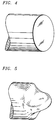
- the microlens By ablating substantially along the 0 and 180 degree rotational positions, the microlens exhibits an elliptical cross sectional area as illustrated in FIGs. 3 and 5.
- the desired eccentricity may be determined empirically by measuring the light distribution produced by the lens and then varying the degree of exposure of the lens to the pulsed beam along the tangential plane.
- the fiber is first subjected to the formation of a symmetric microlens at the end of the fiber as is shown in FIG. 2.
- the rotation of the fiber is stopped and, simultaneously, the laser beam is deactivated.
- the fiber is positioned and progressively moved relative to the beam such that, after the laser beam is reactivated, the fiber is exposed progressively to the cross-sectional edge of the pulsed laser beam to ablate the surface of the symmetric microlens along one tangential plane.
- the fiber is rotated to a position precisely 180° from the first ablating position and the opposite tangential plane is then similarly micromachined, resulting in an asymmetric microlens having an eccentricity between the radii of curvature in the sagittal and tangential planes, see FIG. 3.
- the degree of exposure to the cross-sectional edge of the pulsed laser is selected to attain the desired lens eccentricity, that is, its asymmetry. While the lens is clearly displaying the asymmetric shape, each of the surface contours of the lens is hyperbolic in shape.
- the asymmetric microlens is fabricated on the fiber directly when the fiber is rotating about its longitudinal axis.
- the pulsed laser beam is activated during each revolution at 180° intervals, such as at the 0° and 180° rotational positions of the fiber.
- the desired asymmetry is then achieved by micro-machining an elliptical cross-sectional area, as is shown in FIG. 5.
- FIG. 6 shows an exemplary embodiment of an apparatus 10 for fabricating an asymmetric microlens at the end of a single-mode optical fiber 11 in accordance with the principles of the invention. Except for the use of a rotation sensor and xyz translator, the apparatus is similar to that described in U.S. Patents 4,932,989 and 5,011,254, which are incorporated herein by reference.
- Apparatus, 10 includes a precision xyz translator 12 for stepping fiber, 11, in three dimensions in preselected increments, such as of 0.1 ⁇ m.
- Fiber 11 is secured to translator 12 by fiber holder, 13.
- translator 12 Upon inserting fiber 11 into trough-aperture, 14, formed longitudinally of fiber holder 13 and having a circular cross-section, translator 12 enables fiber 11 to be moved horizontally, vertically, or in any vectorial combination thereof.
- Translator 12 may be controlled manually, by a translator controller, 15, or programmably via computer, 21.
- Rotation of fiber 11 about its longitudinal axis at a rotation speed ranging from 10 to 1000 rpm is provided by mounting the fiber in a suitable spinning device schematically shown as block 16.
- a suitable spinning device schematically shown as block 16.
- Such spinning devices are well known in the art, such as a microlathe driven chuck and the like.
- Free end portion or end facet 17 of optical fiber 11 passes through aperture 14 so that a relatively short end portion of the fiber projects from the fiber holder.
- the length of the fiber projecting from the holder should be long enough to permit formation of a microlens at the end of fiber 11 but short enough to avoid eccentricity in rotation during ablation by a pulsed laser, 18.
- An appropriate length ranges from about 1 mm to a few mm.
- the diameter of through-aperture 14 should be selected such that free rotation is realized between the fiber and inner walls of through-aperture 14 without undue friction therebetween.
- the inner diameter of through-aperture 14 may be up to 2 ⁇ m greater than diameter of fiber 15, resulting in a rotation accuracy to within 1 ⁇ m of the fiber axis.
- Laser 18, which is arranged in a spatial relationship to fiber 11, is used for micromachining an asymmetric microlens on free end portion 17 of fiber 11.
- Laser 18 is provided with suitable optical means 19 and 20 for focusing laser beam 21 onto free end 17 of fiber 11.
- the fiber is engaged by the laser beam perpendicularly to the longitudinal axis of the fiber.
- the fine positioning of laser beam 21 on the free end 17 of fiber 11 is accomplished by moving fiber 11 via translator 12 relative to the beam.
- Rotation sensor schematically shown as block 22, monitors the rotational position of fiber 11.
- Rotation sensor may take many versions as is well-known in the art. Among these is a sensor including a microswitch connected to a laser control. The microswitch is activated at spaced intervals, e.g. at 0° and 180° positions, during the revolution of a spindle of the spinning device, and deactivated at intermediate positions. The ratio of the activated period to the deactivated period determines the ellipticity of the lens.
- Another version includes a disc with clear and opaque sectors, which is attached to the spindle of the device, and a light source and a photocell which are arranged such that a light beam from the light source is interrupted by the opaque sectors of the disc. The signal from the photocell controls a pulse generator to turn the laser beam on and off. The ratio of clear to opaque sectors in the disc determines the ellipticity of the lens.
- Micromachining of the microlens is realized in this exemplary embodiment using a sealed-cavity, RF waveguide CO2 laser 18 emitting approximately 25 watts.
- Other types of lasers such as excimer lasers emitting in the ultraviolet regime, may be used.
- Laser 18 is driven with an external power supply (not shown) that generates RF excitations linked in a known manner to the laser, enabling the laser output to be pulsed under external control with pulse times as short as 10 ⁇ sec.
- the laser output which operates at 10.6 ⁇ m, egresses through a 4X beam expander and is deflected at 90 degrees so that it propagates through focusing lens 20, such as a 7.6 cm focal length zinc selenide lens.
- the focussed spot radius is approximately 15 ⁇ m in diameter, with the greatest energy density within a 5 ⁇ m diameter.
- the power density has been calculated to be approximately 7.1x10 ⁇ 2W/ ⁇ m2.
- the pulsed laser beam is used to flash evaporate portions of the periphery of optical fiber 15 in accordance with the teaching disclosed in U.S. Patent No. 4,710,605, issued to H. M. Presby on December 1, 1987, which is incorporated herein by reference.
- the cross-section of the laser beam engages an outer periphery of the fiber in a direction perpendicular to the longitudinal axis of the fiber, with the intensity and duration of pulses selected in order to progressively ablate and remove the material of the fiber without redeposition such that an asymmetric microlens is formed at the end of fiber.
- the fiber positioning relative to the laser beam and the pulse duration can be adjusted so as to remove material from the fiber to form the desired ellipse.
- the pulse duration is accordingly adjusted to leave along one of the orthogonal axes an amount 2 a from the center core of fiber 11, whereas for a 90° and 270° position, relative to the 0° position, the pulse duration is adjusted such that along the other of the orthogonal axes an amount 2 b of fiber 11 is left from the center of the core.
- the defined ellipse has a length 2 a while along the y-axis the length is 2 b with a being one-half the distance from the center to the outer surface of the ellipse along said one (x) orthogonal axis and b being one-half the distance along the other (y) orthogonal axis.
- the pulse duration is adjusted to leave a lens shape of the desired ellipticity.
- rotation sensor 22 continuously monitors the angular position of the fiber that is exposed to the pulsed laser beam such that a proper amount of material may be ablated.
- the defined elliptical cross-sectional area determines the eccentricity of the microlens formed on the end thereof.
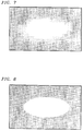
- FIG. 7 Shown in FIG. 7 is a schematic representation of the near-field output of the 0.98 ⁇ m laser diode being used in these coupling experiments. It has an elliptically shaped beam with an aspect ratio of 2.7 to 1. The 1/e mode size is 2.6 ⁇ m by 0.96 ⁇ m. It is seen from the plot shown in FIG. 1 that for this ellipticity an approximately 2 dB coupling loss should result with symmetric microlenses from this asymmetry alone.
- FIG. 8 A schematic representation of the near field output of a lens which was fabricated on standard fiber designed for use at operating wavelengths of 1.3 and 1.5 ⁇ m, is shown in FIG. 8.
- the ellipticity of the beam is about 2.7 to 1 providing an excellent match to the output of the 0.98 ⁇ m laser.
- a coupling efficiency of 84.3 percent (-0.74 dB) was measured with this lens.
- the power output of the laser was measured by collecting all of its output with a high-index ball-lens positioned very close to the laser in order to provide a collimated beam.
- a maximum power of 120 mw was measured into the dominate mode of a single mode fiber with the asymmetric lens.
- the measured power versus current values were almost identical to those measured independently by the laser manufacturer.
- the appropriate axis of the lens was oriented to that of the laser by launching a He-Ne laser beam into the end of the ⁇ 1m long pigtail opposite the lens, observing the projection and rotating the lens. This rotational alignment was not very critical to optimum coupling.
- the ellipticity of the output beams of lenses fabricated to couple to high power 1.48 ⁇ m laser diodes were similar to those for the 0.98 ⁇ m laser diodes, being in the range of 3:1.
Landscapes
- Physics & Mathematics (AREA)
- General Physics & Mathematics (AREA)
- Optics & Photonics (AREA)
- Engineering & Computer Science (AREA)
- Plasma & Fusion (AREA)
- Optical Couplings Of Light Guides (AREA)
- Optical Fibers, Optical Fiber Cores, And Optical Fiber Bundles (AREA)
- Lasers (AREA)
Applications Claiming Priority (2)
| Application Number | Priority Date | Filing Date | Title |
|---|---|---|---|
| US843481 | 1992-02-28 | ||
| US07/843,481 US5256851A (en) | 1992-02-28 | 1992-02-28 | Microlenses for coupling optical fibers to elliptical light beams |
Publications (2)
| Publication Number | Publication Date |
|---|---|
| EP0558230A1 true EP0558230A1 (fr) | 1993-09-01 |
| EP0558230B1 EP0558230B1 (fr) | 1997-04-16 |
Family
ID=25290112
Family Applications (1)
| Application Number | Title | Priority Date | Filing Date |
|---|---|---|---|
| EP93301125A Expired - Lifetime EP0558230B1 (fr) | 1992-02-28 | 1993-02-17 | Methode pour former une microlentille asymmétrique à l'extrémité d'une fibre optique |
Country Status (7)
| Country | Link |
|---|---|
| US (1) | US5256851A (fr) |
| EP (1) | EP0558230B1 (fr) |
| JP (1) | JPH0643336A (fr) |
| KR (1) | KR0155393B1 (fr) |
| CA (1) | CA2085498C (fr) |
| DE (1) | DE69309748T2 (fr) |
| SG (1) | SG65542A1 (fr) |
Cited By (16)
| Publication number | Priority date | Publication date | Assignee | Title |
|---|---|---|---|---|
| EP0633482A3 (en) * | 1993-07-06 | 1995-02-15 | Siecor Corp | Reflectance reduction of glass waveguide ends by partial vaporizing using laser. |
| US5455879A (en) * | 1994-06-22 | 1995-10-03 | Corning Incorporated | Anamorphic microlens for coupling optical fibers to elliptical light beams |
| DE19545721A1 (de) * | 1995-12-07 | 1997-06-12 | Deutsche Telekom Ag | Verfahren zur Herstellung und Justierung von Mikrolinsen auf Faser- und Laser-Enden |
| EP0822429A1 (fr) * | 1996-07-30 | 1998-02-04 | Hewlett-Packard Company | Microlentille à fibre optique et source de rayonnement optique l'utilisant |
| WO2000019253A1 (fr) * | 1998-09-29 | 2000-04-06 | The Furukawa Electric Co., Ltd. | Fibre optique |
| EP1152269A1 (fr) * | 2000-05-05 | 2001-11-07 | Bayerische Motoren Werke Aktiengesellschaft | Dispositifs de terminaison à fibre optique |
| WO2002034452A1 (fr) * | 2000-10-25 | 2002-05-02 | Optek Limited | Procede et appareil de coupe au laser pour fibres ou guides d'ondes optiques |
| WO2002088814A3 (fr) * | 2001-05-01 | 2003-05-01 | Optek Ltd | Ameliorations apportees a des collimateurs de fibres optiques |
| WO2003029853A3 (fr) * | 2001-09-28 | 2003-07-31 | Corning Inc | Appareil et procede pour fabriquer une lentille a l'extremite d'une fibre de guide d'ondes optiques |
| WO2003076992A1 (fr) * | 2002-03-04 | 2003-09-18 | Corning Incorporated | Lentille biconique a fibre optique et son procede de fabrication |
| WO2003076994A1 (fr) * | 2002-03-04 | 2003-09-18 | Corning Incorporated | Fibre optique a dispositif multi-lentille et son procede de fabrication |
| EP1385032A1 (fr) * | 2001-04-30 | 2004-01-28 | JDS Uniphase Corporation | Fibre optique avec terminaison à lentille |
| WO2004055565A1 (fr) * | 2002-12-12 | 2004-07-01 | 3M Innovative Properties Company | Lentille de fibre optique ou de guide d'onde |
| WO2004061501A1 (fr) * | 2002-12-31 | 2004-07-22 | Corning Incorporated | Lentille a fibre optique et procede de fabrication associe |
| WO2005045494A1 (fr) * | 2003-10-31 | 2005-05-19 | Corning Cable Systems Llc | Connecteur installable par l'utilisateur dote d'une fibre optique a element de remplacement pourvue d'une face d'extremite formee au laser |
| US6904197B2 (en) | 2002-03-04 | 2005-06-07 | Corning Incorporated | Beam bending apparatus and method of manufacture |
Families Citing this family (56)
| Publication number | Priority date | Publication date | Assignee | Title |
|---|---|---|---|---|
| US5500913A (en) * | 1993-03-15 | 1996-03-19 | Administrators Of The Tulane Educational Fund | Apparatus and method of fabricating directional fiber optic taps, sensors and other devices with variable angle output |
| US5521999A (en) * | 1994-03-17 | 1996-05-28 | Eastman Kodak Company | Optical system for a laser printer |
| US5511140A (en) * | 1994-10-13 | 1996-04-23 | International Business Machines Corporation | Molded plastic optical fiber-optoelectronic converter subassembly |
| US5701373A (en) * | 1995-10-12 | 1997-12-23 | Sdl, Inc. | Method for improving the coupling efficiency of elliptical light beams into optical waveguides |
| US5751871A (en) * | 1996-01-05 | 1998-05-12 | Ceram Optec Industries, Inc. | Method for coupling of semiconductor lasers into optical fibers |
| US5631991A (en) * | 1996-01-26 | 1997-05-20 | International Business Machines Corporation | Plastic optical subassemblies for light transfer between an optical fiber and an optoelectronic converter and the fabrication of such plastic optical subassemblies |
| JPH10307230A (ja) | 1997-05-07 | 1998-11-17 | Furukawa Electric Co Ltd:The | レンズ付き光ファイバ |
| US6415087B1 (en) | 1997-06-04 | 2002-07-02 | Corning Laserton, Inc. | Polished fused optical fiber endface |
| US6137938A (en) * | 1997-06-04 | 2000-10-24 | Lasertron, Inc. | Flat top, double-angled, wedge-shaped fiber endface |
| US6349159B1 (en) * | 1999-09-02 | 2002-02-19 | Agilent Technologies, Inc. | Lenses that launch high bandwidth modes into a fiber optic cable while eliminating feedback to a laser |
| AU5942000A (en) * | 1999-09-14 | 2001-03-15 | Whitaker Corporation, The | Process for cutting an optical fiber |
| FR2804251B1 (fr) * | 2000-01-26 | 2002-03-08 | France Telecom | Procede et dispositif de commutation en longueur d'onde d'une source laser |
| EP1298460A4 (fr) * | 2000-07-04 | 2005-05-18 | Namiki Precision Jewel Co Ltd | Fibre optique/micro-lentille, fibre optique et technique d'agencement de celle-ci |
| US7099590B2 (en) | 2000-08-25 | 2006-08-29 | R&Dm Foundation | Filtering technique for free space interconnects |
| US7082267B1 (en) | 2000-08-25 | 2006-07-25 | R& Dm Foundation | Shared multi-channel parallel optical interface |
| US6413450B1 (en) | 2000-10-20 | 2002-07-02 | Megladon Manufacturing Group | Thermal shaping of optical fibers |
| US6452700B1 (en) | 2001-01-11 | 2002-09-17 | R&Dm Foundation | Computer backplane employing free space optical interconnect |
| US6533467B2 (en) | 2001-01-11 | 2003-03-18 | Telect, Inc. | Optical fiber ferrule apparatus and method |
| US6853812B2 (en) | 2001-05-09 | 2005-02-08 | Robert Mays, Jr. | Polarized-holographic filtering providing improved extinction ratio |
| US20020191598A1 (en) * | 2001-06-19 | 2002-12-19 | Robert Mays | Network switch employing free-space optical switching technique |
| US20020191254A1 (en) * | 2001-06-19 | 2002-12-19 | Robert Mays | Network routing employing free-space optical broadcasting |
| US6894341B2 (en) * | 2001-12-25 | 2005-05-17 | Kabushiki Kaisha Toshiba | Semiconductor device and manufacturing method |
| US6805491B2 (en) * | 2002-05-20 | 2004-10-19 | Stratos International, Inc. | Stub having an optical fiber |
| US6738544B2 (en) | 2002-06-11 | 2004-05-18 | Megladon Manufacturing Group | Thermally-shaped optical fiber and a method for forming the optical fiber |
| TWI268379B (en) * | 2003-07-07 | 2006-12-11 | National Sun Yat-Sen Univ | Quadrangular-pyramid-shaped lensed fiber and the method of making the same |
| US20050069256A1 (en) * | 2003-09-25 | 2005-03-31 | 3M Innovative Properties Company | Lensed optical fiber and method for making the same |
| US7082250B2 (en) * | 2004-04-15 | 2006-07-25 | Furukawn Electric North America, Inc. | Laser cleaving method and apparatus for optical fiber cables |
| IL164068A0 (en) * | 2004-09-14 | 2005-12-18 | Sagitta Engineering Solutions | A method and apparatus for batch cleaving of fiberoptics conectors before polishing |
| TWI255358B (en) * | 2005-01-21 | 2006-05-21 | Univ Nat Sun Yat Sen | Conical wedge-shaped fiber lens and the method of making the same |
| US8053705B2 (en) * | 2005-09-07 | 2011-11-08 | Purdue Research Foundation | Laser assisted machining process with distributed lasers |
| JP2008070556A (ja) * | 2006-09-13 | 2008-03-27 | Nitto Denko Corp | 光学部材の製造方法および光学部材成形用型の製造方法 |
| CA2560238A1 (fr) * | 2006-09-20 | 2008-03-20 | Institut National D'optique | Systeme optique et methode d'ablation a laser |
| US8604381B1 (en) | 2006-10-12 | 2013-12-10 | Purdue Research Foundation | Integrated laser material processing cell |
| TWI416187B (zh) * | 2008-07-31 | 2013-11-21 | Univ Nat Sun Yat Sen | 中心孔洞之一端具有一元件之結構體及其製造方法 |
| US8905648B2 (en) | 2011-06-29 | 2014-12-09 | Cinch Connectivity Solutions, Inc. | Expanded beam fiber optic connector |
| US9539681B2 (en) | 2011-11-30 | 2017-01-10 | Board Of Trustees Of Northern Illinois University | Laser assisted machining system for ceramics and hard materials |
| US9205609B1 (en) | 2011-12-21 | 2015-12-08 | Corning Cable Systems Llc | Laser cutting and polishing methods for optical fibers and fibers resulting |
| US8764314B2 (en) | 2012-06-15 | 2014-07-01 | Corning Cable Systems Llc | Optical fiber and composite inorganic ferrule assemblies and methods |
| US8985866B2 (en) | 2012-06-20 | 2015-03-24 | Corning Cable Systems Llc | Simultaneous thermal forming of ferrule and optical fiber in a ferrule assembly to thermally form an optical surface in the ferrule assembly, and related fiber optic components, fiber connectors, assemblies, and methods |
| US9205610B1 (en) | 2012-09-17 | 2015-12-08 | Corning Cable Systems Llc | Head-on laser shaping of optical surfaces of optical fibers, and related assemblies and methods |
| US8840318B2 (en) | 2012-10-15 | 2014-09-23 | Corning Cable Systems Llc | Ferrule with stress-isolation feature |
| US8696215B1 (en) | 2012-10-15 | 2014-04-15 | Corning Cable Systems Llc | Adhesive compositions including partially cross-linked resins and coupling agents and methods for use thereof |
| US9039295B2 (en) | 2012-10-15 | 2015-05-26 | Corning Cable Systems Llc | Adhesive compositions including partially cross-linked resins and thermoset resins and methods for use thereof |
| US9568686B2 (en) | 2012-10-15 | 2017-02-14 | Corning Optical Communications LLC | Optical connector and ferrule adhesion system including adhesive composition, and related methods |
| US8753021B1 (en) | 2013-02-12 | 2014-06-17 | Corning Cable Systems Llc | Adhesives for securing optical fibers to ferrules of optical connectors and methods for use thereof |
| US9089931B1 (en) | 2013-03-11 | 2015-07-28 | Corning Cable Systems Llc | Systems and methods for laser cleaving optical fibers |
| US9052469B2 (en) | 2013-04-26 | 2015-06-09 | Corning Cable Systems Llc | Preterminated fiber optic connector sub-assemblies, and related fiber optic connectors, cable assemblies, and methods |
| US8755654B1 (en) | 2013-05-10 | 2014-06-17 | Corning Cable Systems Llc | Coating removal systems for optical fibers |
| US9085047B2 (en) | 2013-05-10 | 2015-07-21 | Corning Optical Communications LLC | Coating removal systems for optical fibers |
| US9588303B2 (en) | 2013-06-03 | 2017-03-07 | Corning Optical Communications LLC | Optical connector with adhesive material |
| US8702322B1 (en) | 2013-06-03 | 2014-04-22 | Corning Cable Systems Llc | Optical connector with adhesive material |
| US9791637B2 (en) | 2014-04-21 | 2017-10-17 | Corning Optical Communications LLC | Methods of terminating one or more optical fibers |
| EP3096163A1 (fr) * | 2015-05-22 | 2016-11-23 | Corning Optical Communications LLC | Dispositifs laser à cascade quantique et procédés de traitement de fibres optiques pour des applications de connecteurs |
| CN110609353B (zh) * | 2019-09-10 | 2020-10-02 | 武汉博昇光电股份有限公司 | 一种转角透镜光纤阵列及其制作方法 |
| CN111624702B (zh) * | 2020-05-10 | 2022-05-17 | 桂林电子科技大学 | 一种正交双轴非球面光纤微透镜 |
| WO2022020587A1 (fr) | 2020-07-22 | 2022-01-27 | Optek Systems, Inc. | Ensemble et procédé de clivage d'un corps en verre avec un laser |
Citations (6)
| Publication number | Priority date | Publication date | Assignee | Title |
|---|---|---|---|---|
| DE2824478A1 (de) * | 1977-06-10 | 1978-12-21 | Philips Nv | Verfahren zur herstellung eines kopplungselementes |
| DE3134508A1 (de) * | 1981-09-01 | 1983-03-17 | Licentia Patent-Verwaltungs-Gmbh, 6000 Frankfurt | "optische faser mit einer anamorphotisch abbildenden endflaeche und verfahren zu deren herstellung" |
| GB2110835A (en) * | 1981-12-01 | 1983-06-22 | Standard Telephones Cables Ltd | Optical fibre having lens-shaped end |
| EP0086155A1 (fr) * | 1982-02-09 | 1983-08-17 | Loic Rivoallan | Procédé de polissage d'une fibre optique, application à la réalisation de dispositifs de couplage optique |
| US4932989A (en) * | 1989-04-05 | 1990-06-12 | At&T Bell Laboratories | Method and apparatus for fabricating microlenses on optical fibers |
| US5011254A (en) * | 1989-11-30 | 1991-04-30 | At&T Bell Laboratories | Coupling of optical devices to optical fibers by means of microlenses |
Family Cites Families (3)
| Publication number | Priority date | Publication date | Assignee | Title |
|---|---|---|---|---|
| US4710605A (en) * | 1985-04-08 | 1987-12-01 | American Telephone And Telegraph Company, At&T Bell Laboratories | Laser nibbling of optical waveguides |
| US5053171A (en) * | 1986-10-14 | 1991-10-01 | Allergan, Inc. | Manufacture of ophthalmic lenses by excimer laser |
| US5061342A (en) * | 1990-05-18 | 1991-10-29 | Bausch & Lomb Incorporated | Target domain profiling of target optical surfaces using excimer laser photoablation |
-
1992
- 1992-02-28 US US07/843,481 patent/US5256851A/en not_active Expired - Lifetime
- 1992-12-16 CA CA002085498A patent/CA2085498C/fr not_active Expired - Fee Related
-
1993
- 1993-02-17 DE DE69309748T patent/DE69309748T2/de not_active Expired - Lifetime
- 1993-02-17 SG SG1996000701A patent/SG65542A1/en unknown
- 1993-02-17 EP EP93301125A patent/EP0558230B1/fr not_active Expired - Lifetime
- 1993-02-26 JP JP5037148A patent/JPH0643336A/ja active Pending
- 1993-02-27 KR KR1019930002919A patent/KR0155393B1/ko not_active Expired - Lifetime
Patent Citations (6)
| Publication number | Priority date | Publication date | Assignee | Title |
|---|---|---|---|---|
| DE2824478A1 (de) * | 1977-06-10 | 1978-12-21 | Philips Nv | Verfahren zur herstellung eines kopplungselementes |
| DE3134508A1 (de) * | 1981-09-01 | 1983-03-17 | Licentia Patent-Verwaltungs-Gmbh, 6000 Frankfurt | "optische faser mit einer anamorphotisch abbildenden endflaeche und verfahren zu deren herstellung" |
| GB2110835A (en) * | 1981-12-01 | 1983-06-22 | Standard Telephones Cables Ltd | Optical fibre having lens-shaped end |
| EP0086155A1 (fr) * | 1982-02-09 | 1983-08-17 | Loic Rivoallan | Procédé de polissage d'une fibre optique, application à la réalisation de dispositifs de couplage optique |
| US4932989A (en) * | 1989-04-05 | 1990-06-12 | At&T Bell Laboratories | Method and apparatus for fabricating microlenses on optical fibers |
| US5011254A (en) * | 1989-11-30 | 1991-04-30 | At&T Bell Laboratories | Coupling of optical devices to optical fibers by means of microlenses |
Non-Patent Citations (1)
| Title |
|---|
| PATENT ABSTRACTS OF JAPAN vol. 12, no. 431 (P-786)15 November 1988 & JP-A-63 163 806 ( FUJITSU ) 7 July 1988 * |
Cited By (24)
| Publication number | Priority date | Publication date | Assignee | Title |
|---|---|---|---|---|
| EP0633482A3 (en) * | 1993-07-06 | 1995-02-15 | Siecor Corp | Reflectance reduction of glass waveguide ends by partial vaporizing using laser. |
| US5455879A (en) * | 1994-06-22 | 1995-10-03 | Corning Incorporated | Anamorphic microlens for coupling optical fibers to elliptical light beams |
| DE19545721C2 (de) * | 1995-12-07 | 2003-02-20 | Deutsche Telekom Ag | Verfahren und Vorrichtung zum Herstellen und präzisen Positionieren von optischen Mikrokomponenten auf einer über einer optischen Einrichtung |
| DE19545721A1 (de) * | 1995-12-07 | 1997-06-12 | Deutsche Telekom Ag | Verfahren zur Herstellung und Justierung von Mikrolinsen auf Faser- und Laser-Enden |
| EP0822429A1 (fr) * | 1996-07-30 | 1998-02-04 | Hewlett-Packard Company | Microlentille à fibre optique et source de rayonnement optique l'utilisant |
| US5940557A (en) * | 1996-07-30 | 1999-08-17 | Hewlett-Packard Company | Optical fibre microlens and optical radiation source employing the same |
| WO2000019253A1 (fr) * | 1998-09-29 | 2000-04-06 | The Furukawa Electric Co., Ltd. | Fibre optique |
| EP1152269A1 (fr) * | 2000-05-05 | 2001-11-07 | Bayerische Motoren Werke Aktiengesellschaft | Dispositifs de terminaison à fibre optique |
| WO2002034452A1 (fr) * | 2000-10-25 | 2002-05-02 | Optek Limited | Procede et appareil de coupe au laser pour fibres ou guides d'ondes optiques |
| CN100537112C (zh) * | 2000-10-25 | 2009-09-09 | 伊鲁维斯有限公司 | 用于光纤或光波导的激光切割方法和装置 |
| US7142741B2 (en) | 2000-10-25 | 2006-11-28 | Iruvis Limited | Laser cutting method and apparatus for optical fibres or waveguides |
| EP1385032A1 (fr) * | 2001-04-30 | 2004-01-28 | JDS Uniphase Corporation | Fibre optique avec terminaison à lentille |
| US6748137B2 (en) | 2001-04-30 | 2004-06-08 | Jds Uniphase Corporation | Lensed optical fiber |
| WO2002088814A3 (fr) * | 2001-05-01 | 2003-05-01 | Optek Ltd | Ameliorations apportees a des collimateurs de fibres optiques |
| WO2003029853A3 (fr) * | 2001-09-28 | 2003-07-31 | Corning Inc | Appareil et procede pour fabriquer une lentille a l'extremite d'une fibre de guide d'ondes optiques |
| WO2003076994A1 (fr) * | 2002-03-04 | 2003-09-18 | Corning Incorporated | Fibre optique a dispositif multi-lentille et son procede de fabrication |
| US6904197B2 (en) | 2002-03-04 | 2005-06-07 | Corning Incorporated | Beam bending apparatus and method of manufacture |
| US6963682B2 (en) | 2002-03-04 | 2005-11-08 | Corning Incorporated | Beam altering fiber lens device and method of manufacture |
| CN1317579C (zh) * | 2002-03-04 | 2007-05-23 | 康宁股份有限公司 | 具有多透镜器件的光纤以及其制造方法 |
| WO2003076992A1 (fr) * | 2002-03-04 | 2003-09-18 | Corning Incorporated | Lentille biconique a fibre optique et son procede de fabrication |
| WO2004055565A1 (fr) * | 2002-12-12 | 2004-07-01 | 3M Innovative Properties Company | Lentille de fibre optique ou de guide d'onde |
| WO2004061501A1 (fr) * | 2002-12-31 | 2004-07-22 | Corning Incorporated | Lentille a fibre optique et procede de fabrication associe |
| US7099535B2 (en) | 2002-12-31 | 2006-08-29 | Corning Incorporated | Small mode-field fiber lens |
| WO2005045494A1 (fr) * | 2003-10-31 | 2005-05-19 | Corning Cable Systems Llc | Connecteur installable par l'utilisateur dote d'une fibre optique a element de remplacement pourvue d'une face d'extremite formee au laser |
Also Published As
| Publication number | Publication date |
|---|---|
| KR0155393B1 (ko) | 1998-12-15 |
| KR930017829A (ko) | 1993-09-20 |
| US5256851A (en) | 1993-10-26 |
| EP0558230B1 (fr) | 1997-04-16 |
| CA2085498A1 (fr) | 1993-08-29 |
| JPH0643336A (ja) | 1994-02-18 |
| CA2085498C (fr) | 1999-02-23 |
| SG65542A1 (en) | 1999-06-22 |
| DE69309748D1 (de) | 1997-05-22 |
| DE69309748T2 (de) | 1997-10-30 |
Similar Documents
| Publication | Publication Date | Title |
|---|---|---|
| US5256851A (en) | Microlenses for coupling optical fibers to elliptical light beams | |
| CA2012696C (fr) | Methode et appareil de fabrication de micro-objectifs montes sur fibre optique | |
| US6822190B2 (en) | Optical fiber or waveguide lens | |
| US7142741B2 (en) | Laser cutting method and apparatus for optical fibres or waveguides | |
| US4710605A (en) | Laser nibbling of optical waveguides | |
| CN100573207C (zh) | 包括具有激光成形端面的抽头光纤的现场安装连接器 | |
| US20080067158A1 (en) | Laser-based ablation method and optical system | |
| US5135555A (en) | Apparatus for fabrication of optical couplers | |
| EP0142026A2 (fr) | Procédé pour construire de micro-lentilles en fin de fibres optiques, spécialement pour des usages bio-médicaux et chirurgicaux et dispositif de réalisation du procédé | |
| HK1080150B (zh) | 光纤对接器 | |
| US20120269488A1 (en) | Methods for preparation and disposing of an optical fiber(s) into a blind hole(s) and related assemblies and methods of making same | |
| US4989936A (en) | Fabrication of optical components utilizing a laser | |
| US5130512A (en) | Fabrication of optical components utilizing a laser | |
| CA2602997A1 (fr) | Systeme optique et methode d'ablation a laser | |
| US7460748B2 (en) | Lensed tip optical fiber and method of making the same | |
| JP2003043288A (ja) | 多心光ファイバ一括処理方法及び装置 | |
| US5026411A (en) | Fabrication of optical couplers | |
| JPS5857722B2 (ja) | 光フアイバ接続器 | |
| CA2319632A1 (fr) | Procede de taille d'une fibre optique | |
| EP1702226A2 (fr) | Fibre optique a pointe presentant une lentille et son procede de fabrication |
Legal Events
| Date | Code | Title | Description |
|---|---|---|---|
| PUAI | Public reference made under article 153(3) epc to a published international application that has entered the european phase |
Free format text: ORIGINAL CODE: 0009012 |
|
| AK | Designated contracting states |
Kind code of ref document: A1 Designated state(s): DE ES FR GB NL SE |
|
| 17P | Request for examination filed |
Effective date: 19940217 |
|
| RAP3 | Party data changed (applicant data changed or rights of an application transferred) |
Owner name: AT&T CORP. |
|
| 17Q | First examination report despatched |
Effective date: 19951016 |
|
| GRAG | Despatch of communication of intention to grant |
Free format text: ORIGINAL CODE: EPIDOS AGRA |
|
| GRAH | Despatch of communication of intention to grant a patent |
Free format text: ORIGINAL CODE: EPIDOS IGRA |
|
| GRAH | Despatch of communication of intention to grant a patent |
Free format text: ORIGINAL CODE: EPIDOS IGRA |
|
| GRAA | (expected) grant |
Free format text: ORIGINAL CODE: 0009210 |
|
| AK | Designated contracting states |
Kind code of ref document: B1 Designated state(s): DE ES FR GB NL SE |
|
| PG25 | Lapsed in a contracting state [announced via postgrant information from national office to epo] |
Ref country code: ES Free format text: THE PATENT HAS BEEN ANNULLED BY A DECISION OF A NATIONAL AUTHORITY Effective date: 19970416 |
|
| REF | Corresponds to: |
Ref document number: 69309748 Country of ref document: DE Date of ref document: 19970522 |
|
| ET | Fr: translation filed | ||
| PG25 | Lapsed in a contracting state [announced via postgrant information from national office to epo] |
Ref country code: SE Effective date: 19970716 |
|
| PLBE | No opposition filed within time limit |
Free format text: ORIGINAL CODE: 0009261 |
|
| STAA | Information on the status of an ep patent application or granted ep patent |
Free format text: STATUS: NO OPPOSITION FILED WITHIN TIME LIMIT |
|
| 26N | No opposition filed | ||
| REG | Reference to a national code |
Ref country code: GB Ref legal event code: IF02 |
|
| PGFP | Annual fee paid to national office [announced via postgrant information from national office to epo] |
Ref country code: FR Payment date: 20120227 Year of fee payment: 20 |
|
| PGFP | Annual fee paid to national office [announced via postgrant information from national office to epo] |
Ref country code: DE Payment date: 20120221 Year of fee payment: 20 |
|
| PGFP | Annual fee paid to national office [announced via postgrant information from national office to epo] |
Ref country code: GB Payment date: 20120221 Year of fee payment: 20 |
|
| PGFP | Annual fee paid to national office [announced via postgrant information from national office to epo] |
Ref country code: NL Payment date: 20120228 Year of fee payment: 20 |
|
| REG | Reference to a national code |
Ref country code: DE Ref legal event code: R071 Ref document number: 69309748 Country of ref document: DE |
|
| REG | Reference to a national code |
Ref country code: DE Ref legal event code: R071 Ref document number: 69309748 Country of ref document: DE |
|
| REG | Reference to a national code |
Ref country code: NL Ref legal event code: V4 Effective date: 20130217 |
|
| REG | Reference to a national code |
Ref country code: GB Ref legal event code: PE20 Expiry date: 20130216 |
|
| PG25 | Lapsed in a contracting state [announced via postgrant information from national office to epo] |
Ref country code: GB Free format text: LAPSE BECAUSE OF EXPIRATION OF PROTECTION Effective date: 20130216 Ref country code: DE Free format text: LAPSE BECAUSE OF EXPIRATION OF PROTECTION Effective date: 20130219 |
|
| REG | Reference to a national code |
Ref country code: GB Ref legal event code: 732E Free format text: REGISTERED BETWEEN 20140102 AND 20140108 |
|
| REG | Reference to a national code |
Ref country code: GB Ref legal event code: 732E Free format text: REGISTERED BETWEEN 20140109 AND 20140115 |