EP0558399A1 - Verfahren zum Verbinden einer Hülse mit einem Rohr und Rohr derart versehen mit einer Hülse - Google Patents
Verfahren zum Verbinden einer Hülse mit einem Rohr und Rohr derart versehen mit einer Hülse Download PDFInfo
- Publication number
- EP0558399A1 EP0558399A1 EP93400460A EP93400460A EP0558399A1 EP 0558399 A1 EP0558399 A1 EP 0558399A1 EP 93400460 A EP93400460 A EP 93400460A EP 93400460 A EP93400460 A EP 93400460A EP 0558399 A1 EP0558399 A1 EP 0558399A1
- Authority
- EP
- European Patent Office
- Prior art keywords
- tube
- ring
- stop
- copper
- aluminum
- Prior art date
- Legal status (The legal status is an assumption and is not a legal conclusion. Google has not performed a legal analysis and makes no representation as to the accuracy of the status listed.)
- Granted
Links
- 238000000034 method Methods 0.000 title claims abstract description 16
- 239000000463 material Substances 0.000 claims abstract description 14
- 229910052751 metal Inorganic materials 0.000 claims abstract description 12
- 239000002184 metal Substances 0.000 claims abstract description 12
- 230000002093 peripheral effect Effects 0.000 claims abstract description 3
- RYGMFSIKBFXOCR-UHFFFAOYSA-N Copper Chemical compound [Cu] RYGMFSIKBFXOCR-UHFFFAOYSA-N 0.000 claims description 16
- 229910052802 copper Inorganic materials 0.000 claims description 16
- 239000010949 copper Substances 0.000 claims description 16
- 239000000956 alloy Substances 0.000 claims description 13
- 229910045601 alloy Inorganic materials 0.000 claims description 13
- 229910052782 aluminium Inorganic materials 0.000 claims description 12
- XAGFODPZIPBFFR-UHFFFAOYSA-N aluminium Chemical compound [Al] XAGFODPZIPBFFR-UHFFFAOYSA-N 0.000 claims description 12
- 239000011159 matrix material Substances 0.000 claims description 9
- 238000003780 insertion Methods 0.000 claims description 3
- 230000037431 insertion Effects 0.000 claims description 3
- 238000004519 manufacturing process Methods 0.000 claims description 3
- 238000007664 blowing Methods 0.000 claims description 2
- 229910000831 Steel Inorganic materials 0.000 description 7
- 239000010959 steel Substances 0.000 description 7
- 238000003754 machining Methods 0.000 description 5
- 230000035939 shock Effects 0.000 description 4
- 150000002739 metals Chemical class 0.000 description 2
- 238000003825 pressing Methods 0.000 description 2
- 238000006073 displacement reaction Methods 0.000 description 1
- 238000009987 spinning Methods 0.000 description 1
Images


Classifications
-
- B—PERFORMING OPERATIONS; TRANSPORTING
- B21—MECHANICAL METAL-WORKING WITHOUT ESSENTIALLY REMOVING MATERIAL; PUNCHING METAL
- B21D—WORKING OR PROCESSING OF SHEET METAL OR METAL TUBES, RODS OR PROFILES WITHOUT ESSENTIALLY REMOVING MATERIAL; PUNCHING METAL
- B21D39/00—Application of procedures in order to connect objects or parts, e.g. coating with sheet metal otherwise than by plating; Tube expanders
- B21D39/04—Application of procedures in order to connect objects or parts, e.g. coating with sheet metal otherwise than by plating; Tube expanders of tubes with tubes; of tubes with rods
Definitions
- the present invention relates to a method for fixing a stop on a tube.
- the invention finds particular application in the production of a part for a circuit breaker, but it applies more generally whenever it is necessary to have a stop on a metal tube of low resilience and that this stop is subjected to repeated and violent shocks.
- FIG. 1 schematically represents, in axial section, end contacts in a breaking chamber of a medium or high voltage circuit breaker.
- a circuit breaker comprising a fixed tubular contact 1 cooperating with contact fingers 2 carried by a tube 3 for the passage of permanent current; the tube 3 carries at its end a stop 3A serving in particular for supporting the fingers 2.
- a tubular part 4 serves as an arcing contact and is pushed against the fixed contact 1 by a spring 5 pressing against a shoulder 4A of the tube 4 .
- the tube 1 When the circuit breaker opens, the tube 1 is driven in the direction of the arrow; the fingers 2 leave the contact 1 and the current then passes through the tubes 1 and 4 which remain in contact thanks to the action of the spring 5. When the stop 3A comes into contact with the shoulder 4A, the tube 4 is driven.
- Tubes 1 and 3 which must conduct the permanent current, must be made of copper or a copper-based alloy; these materials are not very resilient, so that the size of the stop 3A conditions the maximum power of the circuit breaker; in fact, the greater the breaking capacity requested from the device, the faster the displacement of the moving assembly and consequently the more violent is the impact on the stop 3A; room 4, which only conducts the entire current for a short time when the circuit breaker opens, it can be made of more resilient metal, such as steel.
- the solution to the problem consists in using, on a copper tube, a steel stopper with high elastic limit and the problem is to define a method making it possible, to relate on a copper tube, a steel stopper, in a simple way, therefore economical, with the minimum of machining and with great safety in terms of the solidity of the assembly and its resistance to successive shocks during use.
- the material of the ring is chosen from copper and copper-based alloys and aluminum and aluminum-based alloys.
- the tube material is chosen from copper and copper-based alloys and aluminum and aluminum-based alloys.
- the invention also relates to a tube provided with a stop fixed by the above method.
- the ring can serve as a support for elements such as permanent contacts for the passage of current, auxiliary contacts for the insertion of a resistor or a varistor, a blowing nozzle, corona screens, etc.
- a tube 10 made of a slightly resilient metal, for example copper or aluminum, or an alloy based on one of these metals, on which it is desired to fix a steel ring of high elastic limit.
- the tube can be a simple commercial tube obtained by spinning, without machining.
- the tube may be made of aluminum or an aluminum-based alloy.
- the ring which it is desired to fix to the tube is an inner ring to the tube. It is understood that this arrangement is not limiting and that the method of the invention applies, mutatis mutandis, to the fixing of an outer ring to the tube. Likewise, the ring is indifferently attached to the end of the tube or at any point along the length of the latter.
- the ring 11 has a portion having an outside diameter equal to the inside diameter of the tube 10 and it is provided at its periphery with a groove 11A.
- the ring rests on a metal core 12, for example made of steel.
- a metal ring 13 accepting strong plastic deformation, for example aluminum or copper or an alloy based on one of these metals.
- the ring rests on a shoulder 15A of a substantially tubular metal matrix 15, made for example of steel; the inside diameter of the matrix 15, below the shoulder 15A, is equal, apart from the clearance, to the outside diameter of the tube 10; above the shoulder 15A, the internal diameter of the matrix 15 is equal, apart from the clearance, to the diameter of the tube increased by twice the thickness of the ring, which leaves, above the ring , an annular space in which is placed a tubular punch 16.
- the copper tube 10 deforms and fills the groove 11A; the ring is deformed and its height is reduced.
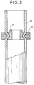
- the tube with its stopper is shown in Figure 3, after the die and the punch have been removed.
- the assembly of the stop of the tube and the ring constitutes a thick and very homogeneous block capable of withstanding repeated shocks, in particular during operating maneuvers when it is used for the constitution of a high or medium voltage circuit breaker.
- the ring 13 held in place can serve as a fixing piece for elements of a circuit breaker, for example contact fingers for the permanent passage of current, auxiliary contacts for the insertion of a resistor or varistor, hoods, air blower, etc.
- the method of the invention makes it possible to assemble with a minimum of machining, therefore at the lowest cost, a steel stop with high elastic limit on a low resilience conductive tube obtained without machining.
- the fixing element used namely the ring, made of metal or alloy accepting a strong plastic deformation, is an element produced very economically.
- the stop-ring assembly fixed very rigidly, can be subjected to violent and repeated shocks, and constitutes a block which can be used as a support for other parts, depending on the application envisaged.
Landscapes
- Engineering & Computer Science (AREA)
- Mechanical Engineering (AREA)
- Shaping Metal By Deep-Drawing, Or The Like (AREA)
- Non-Disconnectible Joints And Screw-Threaded Joints (AREA)
- Lining Or Joining Of Plastics Or The Like (AREA)
- Adhesives Or Adhesive Processes (AREA)
- Supports For Pipes And Cables (AREA)
- Pipe Accessories (AREA)
- Clamps And Clips (AREA)
- Mutual Connection Of Rods And Tubes (AREA)
Applications Claiming Priority (2)
| Application Number | Priority Date | Filing Date | Title |
|---|---|---|---|
| FR9202158 | 1992-02-25 | ||
| FR9202158A FR2687594B1 (fr) | 1992-02-25 | 1992-02-25 | Procede de fixation d'une butee sur un tube et tube muni d'une butee realisee selon le procede. |
Publications (2)
| Publication Number | Publication Date |
|---|---|
| EP0558399A1 true EP0558399A1 (de) | 1993-09-01 |
| EP0558399B1 EP0558399B1 (de) | 1996-10-30 |
Family
ID=9427001
Family Applications (1)
| Application Number | Title | Priority Date | Filing Date |
|---|---|---|---|
| EP93400460A Expired - Lifetime EP0558399B1 (de) | 1992-02-25 | 1993-02-23 | Verfahren zum Verbinden einer Hülse mit einem Rohr und Rohr derart versehen mit einer Hülse |
Country Status (7)
| Country | Link |
|---|---|
| EP (1) | EP0558399B1 (de) |
| AT (1) | ATE144732T1 (de) |
| DE (1) | DE69305666T2 (de) |
| DK (1) | DK0558399T3 (de) |
| ES (1) | ES2093371T3 (de) |
| FR (1) | FR2687594B1 (de) |
| GR (1) | GR3021720T3 (de) |
Cited By (2)
| Publication number | Priority date | Publication date | Assignee | Title |
|---|---|---|---|---|
| EP1144797A1 (de) | 1998-11-23 | 2001-10-17 | Valto ILOMÄKI | Verfahren zum anbringen eines futterrohrschuhs an einer bohrvorrichtung |
| EP4272885A1 (de) * | 2022-05-02 | 2023-11-08 | Meleghy Automotive GmbH & Co. KG | Verfahren zur befestigung eines buchsenkörpers in einem rohrkörper |
Citations (3)
| Publication number | Priority date | Publication date | Assignee | Title |
|---|---|---|---|---|
| US2852843A (en) * | 1955-04-25 | 1958-09-23 | Aerojet General Co | Method of making metal joint |
| US3529856A (en) * | 1969-01-08 | 1970-09-22 | Dumont Aviat Associates | Coupling and method of forming same |
| US3590464A (en) * | 1969-03-07 | 1971-07-06 | Gulf Energy & Environ Systems | Threaded fastener and method of making the same |
-
1992
- 1992-02-25 FR FR9202158A patent/FR2687594B1/fr not_active Expired - Fee Related
-
1993
- 1993-02-23 DE DE69305666T patent/DE69305666T2/de not_active Expired - Fee Related
- 1993-02-23 DK DK93400460.7T patent/DK0558399T3/da active
- 1993-02-23 ES ES93400460T patent/ES2093371T3/es not_active Expired - Lifetime
- 1993-02-23 AT AT93400460T patent/ATE144732T1/de not_active IP Right Cessation
- 1993-02-23 EP EP93400460A patent/EP0558399B1/de not_active Expired - Lifetime
-
1996
- 1996-11-20 GR GR960403115T patent/GR3021720T3/el unknown
Patent Citations (3)
| Publication number | Priority date | Publication date | Assignee | Title |
|---|---|---|---|---|
| US2852843A (en) * | 1955-04-25 | 1958-09-23 | Aerojet General Co | Method of making metal joint |
| US3529856A (en) * | 1969-01-08 | 1970-09-22 | Dumont Aviat Associates | Coupling and method of forming same |
| US3590464A (en) * | 1969-03-07 | 1971-07-06 | Gulf Energy & Environ Systems | Threaded fastener and method of making the same |
Cited By (2)
| Publication number | Priority date | Publication date | Assignee | Title |
|---|---|---|---|---|
| EP1144797A1 (de) | 1998-11-23 | 2001-10-17 | Valto ILOMÄKI | Verfahren zum anbringen eines futterrohrschuhs an einer bohrvorrichtung |
| EP4272885A1 (de) * | 2022-05-02 | 2023-11-08 | Meleghy Automotive GmbH & Co. KG | Verfahren zur befestigung eines buchsenkörpers in einem rohrkörper |
Also Published As
| Publication number | Publication date |
|---|---|
| ATE144732T1 (de) | 1996-11-15 |
| FR2687594B1 (fr) | 1994-04-08 |
| DE69305666T2 (de) | 1997-02-27 |
| ES2093371T3 (es) | 1996-12-16 |
| DE69305666D1 (de) | 1996-12-05 |
| FR2687594A1 (fr) | 1993-08-27 |
| EP0558399B1 (de) | 1996-10-30 |
| DK0558399T3 (da) | 1996-11-25 |
| GR3021720T3 (en) | 1997-02-28 |
Similar Documents
| Publication | Publication Date | Title |
|---|---|---|
| EP0016669A1 (de) | Montagemuffe zum Befestigen einer Schraube in einem Gegenstand, insbesondere aus weichem Material | |
| FR2918509A1 (fr) | Traversee metal - materiau de fixation | |
| EP0558399B1 (de) | Verfahren zum Verbinden einer Hülse mit einem Rohr und Rohr derart versehen mit einer Hülse | |
| FR2540758A1 (fr) | Outillage de formage a froid de pieces metalliques comportant des elements axiaux opposes | |
| EP0516559B1 (de) | Verfahren zum Schweissen von Kupferteilen | |
| FR2726208A1 (fr) | Procede de retreint | |
| EP0195474A2 (de) | Flanschbüchsenlager und sein Herstellungsverfahren | |
| FR2902244A1 (fr) | Procede et dispositif pour relier plusieurs cables avec un element, et douille de rivetage. | |
| EP0323931B1 (de) | Verfahren und Werkzeugausrüstung zur Herstellung geschmiedeter Niete | |
| EP1160027B1 (de) | Aufweitzange | |
| CH372286A (fr) | Matrice | |
| EP0119467B1 (de) | Verfahren zur Befestigung einer schmiedbaren Metallhülse auf einem Stab aus Verbundmaterial und durch die Ausführung dieses Verfahrens erhaltener Isolator | |
| EP0677901B1 (de) | Krimpverfahren für Leiterenden und Kontaktelement dafür | |
| EP0811547B1 (de) | Verbesserung an Federspannern | |
| EP0667196A1 (de) | Verfahren zur Herstellung von massivköpfigen mechanischen Strukturen aus Rohren und Vorrichtung dafür | |
| EP1317355B1 (de) | Befestigungsverfahren für mindestens einen führungseinsatz zwischen zwei koaxialen rohren, bevorzugt in einem kraftfahrzeug-stabilisator | |
| EP0187582B1 (de) | Pressscheibe zum Strangpressen von Metall | |
| FR3155945A1 (fr) | Tige de conduction de courant électrique pour ampoule à vide | |
| FR2827532A1 (fr) | Outil de faconnage | |
| EP4095878B1 (de) | Unterbrechungssystem eines elektrischen geräts | |
| EP1620653B1 (de) | Verfahren zur montage einer palette an einer vollen stösselstange und entsprechende montage | |
| FR2557846A1 (fr) | Dispositif et procede d'assemblage precis des organes de pedale pour cycles et vehicules similaires, et les pedales montees selon ce dispositif | |
| EP0016715A1 (de) | Dichtungsvorrichtung und Verfahren zum dichten Zusammenfügen einer Muffe mit einem isolierten elektrischen Leiter oder einem Rohr und deren Herstellungsverfahren | |
| BE368234A (de) | ||
| FR3116455A1 (fr) | Dispositif coupe-tube |
Legal Events
| Date | Code | Title | Description |
|---|---|---|---|
| PUAI | Public reference made under article 153(3) epc to a published international application that has entered the european phase |
Free format text: ORIGINAL CODE: 0009012 |
|
| AK | Designated contracting states |
Kind code of ref document: A1 Designated state(s): AT BE CH DE DK ES FR GB GR IE IT LI LU NL PT SE |
|
| 17P | Request for examination filed |
Effective date: 19940108 |
|
| 17Q | First examination report despatched |
Effective date: 19951116 |
|
| GRAG | Despatch of communication of intention to grant |
Free format text: ORIGINAL CODE: EPIDOS AGRA |
|
| GRAH | Despatch of communication of intention to grant a patent |
Free format text: ORIGINAL CODE: EPIDOS IGRA |
|
| GRAH | Despatch of communication of intention to grant a patent |
Free format text: ORIGINAL CODE: EPIDOS IGRA |
|
| GRAA | (expected) grant |
Free format text: ORIGINAL CODE: 0009210 |
|
| AK | Designated contracting states |
Kind code of ref document: B1 Designated state(s): AT BE CH DE DK ES FR GB GR IE IT LI LU NL PT SE |
|
| REF | Corresponds to: |
Ref document number: 144732 Country of ref document: AT Date of ref document: 19961115 Kind code of ref document: T |
|
| ITF | It: translation for a ep patent filed | ||
| REG | Reference to a national code |
Ref country code: CH Ref legal event code: NV Representative=s name: GEC ALSTHOM (SUISSE) S.A. DEPARTEMENT DES BREVETS |
|
| GBT | Gb: translation of ep patent filed (gb section 77(6)(a)/1977) |
Effective date: 19961030 |
|
| REG | Reference to a national code |
Ref country code: DK Ref legal event code: T3 |
|
| REF | Corresponds to: |
Ref document number: 69305666 Country of ref document: DE Date of ref document: 19961205 |
|
| REG | Reference to a national code |
Ref country code: IE Ref legal event code: FG4D Free format text: 70472 |
|
| REG | Reference to a national code |
Ref country code: ES Ref legal event code: FG2A Ref document number: 2093371 Country of ref document: ES Kind code of ref document: T3 |
|
| REG | Reference to a national code |
Ref country code: GR Ref legal event code: FG4A Free format text: 3021720 |
|
| REG | Reference to a national code |
Ref country code: PT Ref legal event code: SC4A Free format text: AVAILABILITY OF NATIONAL TRANSLATION Effective date: 19961031 |
|
| PLBE | No opposition filed within time limit |
Free format text: ORIGINAL CODE: 0009261 |
|
| STAA | Information on the status of an ep patent application or granted ep patent |
Free format text: STATUS: NO OPPOSITION FILED WITHIN TIME LIMIT |
|
| 26N | No opposition filed | ||
| PGFP | Annual fee paid to national office [announced via postgrant information from national office to epo] |
Ref country code: LU Payment date: 20000124 Year of fee payment: 8 |
|
| PG25 | Lapsed in a contracting state [announced via postgrant information from national office to epo] |
Ref country code: LU Free format text: LAPSE BECAUSE OF NON-PAYMENT OF DUE FEES Effective date: 20010223 |
|
| REG | Reference to a national code |
Ref country code: GB Ref legal event code: IF02 |
|
| PGFP | Annual fee paid to national office [announced via postgrant information from national office to epo] |
Ref country code: GB Payment date: 20020115 Year of fee payment: 10 |
|
| PGFP | Annual fee paid to national office [announced via postgrant information from national office to epo] |
Ref country code: CH Payment date: 20020117 Year of fee payment: 10 |
|
| PGFP | Annual fee paid to national office [announced via postgrant information from national office to epo] |
Ref country code: IE Payment date: 20020121 Year of fee payment: 10 |
|
| PGFP | Annual fee paid to national office [announced via postgrant information from national office to epo] |
Ref country code: PT Payment date: 20020123 Year of fee payment: 10 |
|
| PGFP | Annual fee paid to national office [announced via postgrant information from national office to epo] |
Ref country code: NL Payment date: 20020129 Year of fee payment: 10 Ref country code: AT Payment date: 20020129 Year of fee payment: 10 |
|
| PGFP | Annual fee paid to national office [announced via postgrant information from national office to epo] |
Ref country code: GR Payment date: 20020131 Year of fee payment: 10 |
|
| PGFP | Annual fee paid to national office [announced via postgrant information from national office to epo] |
Ref country code: SE Payment date: 20020204 Year of fee payment: 10 Ref country code: DK Payment date: 20020204 Year of fee payment: 10 |
|
| PGFP | Annual fee paid to national office [announced via postgrant information from national office to epo] |
Ref country code: FR Payment date: 20020207 Year of fee payment: 10 Ref country code: DE Payment date: 20020207 Year of fee payment: 10 |
|
| PGFP | Annual fee paid to national office [announced via postgrant information from national office to epo] |
Ref country code: ES Payment date: 20020214 Year of fee payment: 10 |
|
| PGFP | Annual fee paid to national office [announced via postgrant information from national office to epo] |
Ref country code: BE Payment date: 20020227 Year of fee payment: 10 |
|
| PG25 | Lapsed in a contracting state [announced via postgrant information from national office to epo] |
Ref country code: GB Free format text: LAPSE BECAUSE OF NON-PAYMENT OF DUE FEES Effective date: 20030223 Ref country code: AT Free format text: LAPSE BECAUSE OF NON-PAYMENT OF DUE FEES Effective date: 20030223 |
|
| PG25 | Lapsed in a contracting state [announced via postgrant information from national office to epo] |
Ref country code: SE Free format text: LAPSE BECAUSE OF NON-PAYMENT OF DUE FEES Effective date: 20030224 Ref country code: IE Free format text: LAPSE BECAUSE OF NON-PAYMENT OF DUE FEES Effective date: 20030224 Ref country code: ES Free format text: LAPSE BECAUSE OF NON-PAYMENT OF DUE FEES Effective date: 20030224 |
|
| PG25 | Lapsed in a contracting state [announced via postgrant information from national office to epo] |
Ref country code: LI Free format text: LAPSE BECAUSE OF NON-PAYMENT OF DUE FEES Effective date: 20030228 Ref country code: DK Free format text: LAPSE BECAUSE OF NON-PAYMENT OF DUE FEES Effective date: 20030228 Ref country code: CH Free format text: LAPSE BECAUSE OF NON-PAYMENT OF DUE FEES Effective date: 20030228 Ref country code: BE Free format text: LAPSE BECAUSE OF NON-PAYMENT OF DUE FEES Effective date: 20030228 |
|
| PG25 | Lapsed in a contracting state [announced via postgrant information from national office to epo] |
Ref country code: PT Free format text: LAPSE BECAUSE OF NON-PAYMENT OF DUE FEES Effective date: 20030831 |
|
| PG25 | Lapsed in a contracting state [announced via postgrant information from national office to epo] |
Ref country code: NL Free format text: LAPSE BECAUSE OF NON-PAYMENT OF DUE FEES Effective date: 20030901 |
|
| PG25 | Lapsed in a contracting state [announced via postgrant information from national office to epo] |
Ref country code: DE Free format text: LAPSE BECAUSE OF NON-PAYMENT OF DUE FEES Effective date: 20030902 |
|
| PG25 | Lapsed in a contracting state [announced via postgrant information from national office to epo] |
Ref country code: GR Free format text: LAPSE BECAUSE OF NON-PAYMENT OF DUE FEES Effective date: 20030904 |
|
| EUG | Se: european patent has lapsed | ||
| REG | Reference to a national code |
Ref country code: DK Ref legal event code: EBP |
|
| GBPC | Gb: european patent ceased through non-payment of renewal fee | ||
| REG | Reference to a national code |
Ref country code: CH Ref legal event code: PL |
|
| PG25 | Lapsed in a contracting state [announced via postgrant information from national office to epo] |
Ref country code: FR Free format text: LAPSE BECAUSE OF NON-PAYMENT OF DUE FEES Effective date: 20031031 |
|
| NLV4 | Nl: lapsed or anulled due to non-payment of the annual fee |
Effective date: 20030901 |
|
| REG | Reference to a national code |
Ref country code: FR Ref legal event code: ST |
|
| REG | Reference to a national code |
Ref country code: IE Ref legal event code: MM4A |
|
| REG | Reference to a national code |
Ref country code: ES Ref legal event code: FD2A Effective date: 20030224 |
|
| PG25 | Lapsed in a contracting state [announced via postgrant information from national office to epo] |
Ref country code: IT Free format text: LAPSE BECAUSE OF NON-PAYMENT OF DUE FEES;WARNING: LAPSES OF ITALIAN PATENTS WITH EFFECTIVE DATE BEFORE 2007 MAY HAVE OCCURRED AT ANY TIME BEFORE 2007. THE CORRECT EFFECTIVE DATE MAY BE DIFFERENT FROM THE ONE RECORDED. Effective date: 20050223 |