EP0558458A1 - Regenerativ-Verbrennungsofen zum Entfernen umweltschädlicher Emissionen, insbesondere zur Verarbeitung von Emissionen, die Lackrückstände enthalten - Google Patents
Regenerativ-Verbrennungsofen zum Entfernen umweltschädlicher Emissionen, insbesondere zur Verarbeitung von Emissionen, die Lackrückstände enthalten Download PDFInfo
- Publication number
- EP0558458A1 EP0558458A1 EP93830015A EP93830015A EP0558458A1 EP 0558458 A1 EP0558458 A1 EP 0558458A1 EP 93830015 A EP93830015 A EP 93830015A EP 93830015 A EP93830015 A EP 93830015A EP 0558458 A1 EP0558458 A1 EP 0558458A1
- Authority
- EP
- European Patent Office
- Prior art keywords
- chambers
- incinerator
- wall
- regenerative incinerator
- space
- Prior art date
- Legal status (The legal status is an assumption and is not a legal conclusion. Google has not performed a legal analysis and makes no representation as to the accuracy of the status listed.)
- Withdrawn
Links
Images

Classifications
-
- F—MECHANICAL ENGINEERING; LIGHTING; HEATING; WEAPONS; BLASTING
- F23—COMBUSTION APPARATUS; COMBUSTION PROCESSES
- F23G—CREMATION FURNACES; CONSUMING WASTE PRODUCTS BY COMBUSTION
- F23G7/00—Incinerators or other apparatus for consuming industrial waste, e.g. chemicals
- F23G7/06—Incinerators or other apparatus for consuming industrial waste, e.g. chemicals of waste gases or noxious gases, e.g. exhaust gases
- F23G7/061—Incinerators or other apparatus for consuming industrial waste, e.g. chemicals of waste gases or noxious gases, e.g. exhaust gases with supplementary heating
- F23G7/065—Incinerators or other apparatus for consuming industrial waste, e.g. chemicals of waste gases or noxious gases, e.g. exhaust gases with supplementary heating using gaseous or liquid fuel
- F23G7/066—Incinerators or other apparatus for consuming industrial waste, e.g. chemicals of waste gases or noxious gases, e.g. exhaust gases with supplementary heating using gaseous or liquid fuel preheating the waste gas by the heat of the combustion, e.g. recuperation type incinerator
- F23G7/068—Incinerators or other apparatus for consuming industrial waste, e.g. chemicals of waste gases or noxious gases, e.g. exhaust gases with supplementary heating using gaseous or liquid fuel preheating the waste gas by the heat of the combustion, e.g. recuperation type incinerator using regenerative heat recovery means
Definitions
- the present invention relates to a regenerative incinerator for damping or reducing polluting emissions, in particular for processing paint residue containing emissions.
- the air purification systems which are at present used in this field have high assembling and maintenance costs, and they do not always provide a satisfactory reduction of the toxic and noxious substances entrained by this air.
- the aim of the present invention is to overcome the above mentioned problems, by providing a regenerative incinerator for damping or reducing polluting emissions, which is adapted to efficiently purify the air being processed.
- a main object of the present invention is to provide a regenerative inclinerator which is specifically designed for processing air containing volatile and inflammable substances.
- Another object of the present invention is to provide such a regenerative incinerator which can be easily constructed and has a very reduced maintenance cost.
- a regenerative incinerator for damping polluting emissions, characterized in that said regenerative incinerator comprises an incinerator body in which is defined a processing cavity divided into at least two filtering material containing chambers.
- the above mentioned chambers communicate, respectively, with an inlet duct for a fluid to be processed and an outlet duct for the outlet of the processed fluid, said fluid being caused to pass, successively, through one of the filtering material containing chambers, through the high temperature space and through the other filtering material containing chamber.
- This cycle is reversed, with a timing of about two minutes, in order to hold a constant and homogeneous thermal gradient in the sand.
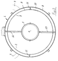
- the regenerative incinerator comprises an incinerator body 1, in which there is defined a processing cavity, which is divided into at least two chambers, respectively indicated at 2 and 3, in which a filtering material is located.
- a space 4 which is separated from the two chambers 2 and 3 by means of a perforated wall 5, and in which there are arranged heating means, for example electrical resistances of any known types and which have not been specifically shown for simplicity, so as to hold the space 4 at a high temperature, preferably from 700°C and 900°C.
- the fluid to be processed is introduced in. to the regenerative incinerator by means of a pumping or sucking or drawing operation, so as to cause said fluid to successively pass through the chamber 2, the high temperature space 4 and the other chamber 3, as it will become more apparent hereinafter.
- This operating cycle will be advantageously automatically reversed preferably with a timing of about 2 minutes.
- the incinerator body 1 comprises a cylinder, in which there is coaxially formed the mentioned space 4, also of cylindric shape, and being delimited by the perforated sheet metal wall 5.
- a holding net 9 for holding a filtering material located in the chambers 2 and 3 and, between the net 9 and outer wall 8 there is defined a gap 10.
- the net 9 is laterally supported by suitable spacer means 11, arranged between the net 9 and outer wall 8.
- the net 9 is supported by a perforated sheet metal element.
- the inside of the incinerator body 1 is divided into two substantially like portions by means of a pair of radially extending walls, respectively indicated at 12 and 13, which are arranged at a diametrical plane and tightly separating the chamber 2 from the chamber 3, as well as the respective portions of the gap 10.
- the inlet duct 6 is connected to a hole, formed through the outer wall 8, at the chamber 2 region, whereas the outlet duct 7 is connected to a hole formed through the outer wall 8 at the chamber 3.
- the filtering material contained in said chambers 2 and 3 comprises sand or siliceous gravel.
- a layer 14 of siliceous gravel, of small particle size, is provided in abutment against the perforated wall 5, whereas the remaining portion of the chambers 2 and 3 is also filled by siliceous gravel 15 of finer particle size.
- a base layer 16 of a thermally insulating material such as, for example, a ceramic fibre and/or mineral wool layer, which does not affect the gap 10.
- the top portion of the body 1 is covered by a cover element 17, through the central part of which, at the space 4, there is formed a hole closed by a plug element 18.
- the cover or cap element 17 and plug 18 are suitably thermally insulated, preferably by means of an inner insulating layer 19, made of ceramic fibers, and by means of a mineral wool outer layer 20.
- a further thermally insulating layer of the ceramic fibre type.
- the above disclosed incinerator operates as follows.
- the air to be processed, containing inflammable and volatile substances, is entrained, under a suitable pressure, inside the incinerator body 1 through the inlet duct 6.
- the polluted air is conveyed to the space 4, passing through the sand or gravel layer arranged inside the chamber 2.
- the sand will provide a thermal "flywheel” or storing means (having a high thermal capacity) which will allow a desired temperature to be easily held with a reduced power requirement by the electric resistances.
- the increasing thermal gradient inside the sand containing spaces will provide a gradual oxidation of the several components of the solvents to be processed.
- the combustion residue, passing through the sand or gravel in the chamber 3, will be filtered and progresssively cooled, and will release into the sand an amount of energy which will actually correspond to the energy or power amount supplied by the heating elements, apart from some losses.
- the advancement speed of the air through the chambers 2 and 3 will be of about 0.5 m/second.
- a regenerative incinerator which is specifically designed to provide very good results even if the air to be processed is polluted by volatile-inflammable substances very toxic or noxious.
- the used material provided that they are compatible to the intended use, as well as the contingent size and shapes, can be any, according to requirements.
Landscapes
- Engineering & Computer Science (AREA)
- Environmental & Geological Engineering (AREA)
- Mechanical Engineering (AREA)
- General Engineering & Computer Science (AREA)
- Incineration Of Waste (AREA)
Applications Claiming Priority (2)
| Application Number | Priority Date | Filing Date | Title |
|---|---|---|---|
| ITMI920175A IT1258834B (it) | 1992-01-30 | 1992-01-30 | Inceneritore rigenerativo per l'abbattimento di emissioni inquinanti in particolare per il trattamento delle emissioni contenenti residui di vernici |
| ITMI920175 | 1992-01-30 |
Publications (1)
| Publication Number | Publication Date |
|---|---|
| EP0558458A1 true EP0558458A1 (de) | 1993-09-01 |
Family
ID=11361735
Family Applications (1)
| Application Number | Title | Priority Date | Filing Date |
|---|---|---|---|
| EP93830015A Withdrawn EP0558458A1 (de) | 1992-01-30 | 1993-01-21 | Regenerativ-Verbrennungsofen zum Entfernen umweltschädlicher Emissionen, insbesondere zur Verarbeitung von Emissionen, die Lackrückstände enthalten |
Country Status (2)
| Country | Link |
|---|---|
| EP (1) | EP0558458A1 (de) |
| IT (1) | IT1258834B (de) |
Families Citing this family (1)
| Publication number | Priority date | Publication date | Assignee | Title |
|---|---|---|---|---|
| CN116182170A (zh) * | 2023-03-15 | 2023-05-30 | 昆山工统环保科技有限公司 | 一种用于挥发性有机物废气处理的蓄热式焚烧炉 |
Citations (4)
| Publication number | Priority date | Publication date | Assignee | Title |
|---|---|---|---|---|
| GB2044900A (en) * | 1979-03-28 | 1980-10-22 | Nittetsu Kakoki Kk | Incinerator and method for treating gases for removing impurities |
| US4802423A (en) * | 1987-12-01 | 1989-02-07 | Regenerative Environmental Equipment Co. Inc. | Combustion apparatus with auxiliary burning unit for liquid fluids |
| EP0440181A2 (de) * | 1990-01-30 | 1991-08-07 | LTG Lufttechnische GmbH | Regenerativ-Reaktor zum Verbrennen von industriellen Abgasen |
| US5163829A (en) * | 1991-07-24 | 1992-11-17 | Thermo Electron Wisconsin, Inc. | Compact regenerative incinerator |
-
1992
- 1992-01-30 IT ITMI920175A patent/IT1258834B/it active IP Right Grant
-
1993
- 1993-01-21 EP EP93830015A patent/EP0558458A1/de not_active Withdrawn
Patent Citations (4)
| Publication number | Priority date | Publication date | Assignee | Title |
|---|---|---|---|---|
| GB2044900A (en) * | 1979-03-28 | 1980-10-22 | Nittetsu Kakoki Kk | Incinerator and method for treating gases for removing impurities |
| US4802423A (en) * | 1987-12-01 | 1989-02-07 | Regenerative Environmental Equipment Co. Inc. | Combustion apparatus with auxiliary burning unit for liquid fluids |
| EP0440181A2 (de) * | 1990-01-30 | 1991-08-07 | LTG Lufttechnische GmbH | Regenerativ-Reaktor zum Verbrennen von industriellen Abgasen |
| US5163829A (en) * | 1991-07-24 | 1992-11-17 | Thermo Electron Wisconsin, Inc. | Compact regenerative incinerator |
Also Published As
| Publication number | Publication date |
|---|---|
| ITMI920175A1 (it) | 1993-07-30 |
| ITMI920175A0 (it) | 1992-01-30 |
| IT1258834B (it) | 1996-02-29 |
Similar Documents
| Publication | Publication Date | Title |
|---|---|---|
| US5993748A (en) | Hot gas extraction device for volatizing at least one substituent of a material | |
| US5873919A (en) | System for removal of noxious fumes | |
| US4989408A (en) | Device for removing soot from diesel exhaust | |
| KR900000110A (ko) | 더운, 개스형태의 또는 액상의 매질로부터 고체연료 미립자를 분리하기 위한 휠터 | |
| GB2098086A (en) | Method and apparatus for removing soot from internal combustion engine exhaust filters | |
| US4807695A (en) | Regenerator for a regenerative heating system | |
| KR20080023209A (ko) | 입자상 물질 제거 장치 | |
| CN105588133B (zh) | 一种旋转式蓄热燃烧及氧化处理装置 | |
| US5173919A (en) | Manipulation of the exit gas flow in a melting furnace | |
| US5405261A (en) | Waste oil fired heater with improved two-stage combustion chamber | |
| US5593471A (en) | Dust collecting apparatus | |
| AU2855601A (en) | Method and device for the autocombustion of oily organic waste, comprising a tangential heating furnace | |
| EP1606554B1 (de) | Verfahren und vorrichtung zur reduktion von abgasemissionen | |
| SE8902928D0 (sv) | Filteraggregat foer rening av tilluft | |
| KR19990022767A (ko) | 파이프 모쥴 | |
| RU2060834C1 (ru) | Устройство для очистки газа от примесей | |
| JPS6226312A (ja) | 集塵器 | |
| SE439949B (sv) | Partikelfilter, for rening av avgaser fran forbrenningsmotor, kompletterat med katalysatorer | |
| IT214604Z2 (it) | Gruppo di filtraggio dell aria per un veicolo industriale | |
| KR100221677B1 (ko) | 유해가스 소각장치 | |
| SU1605093A1 (ru) | Устройство термического обезвреживани газов | |
| US4190415A (en) | Chip drying and cleaning device | |
| EP0620034B1 (de) | Staubabscheider für heisse Gase | |
| JPS6238113Y2 (de) | ||
| CN209221823U (zh) | 一种工业废气组合式蜡质去除设备 |
Legal Events
| Date | Code | Title | Description |
|---|---|---|---|
| PUAI | Public reference made under article 153(3) epc to a published international application that has entered the european phase |
Free format text: ORIGINAL CODE: 0009012 |
|
| AK | Designated contracting states |
Kind code of ref document: A1 Designated state(s): AT BE DE ES FR GB PT SE |
|
| 17P | Request for examination filed |
Effective date: 19940120 |
|
| STAA | Information on the status of an ep patent application or granted ep patent |
Free format text: STATUS: THE APPLICATION HAS BEEN WITHDRAWN |
|
| 18W | Application withdrawn |
Withdrawal date: 19950117 |