EP0558828B1 - Double filtre pour lubrifiants de moteur de véhicule, avec une cartouche compressible de filtrage très fin - Google Patents
Double filtre pour lubrifiants de moteur de véhicule, avec une cartouche compressible de filtrage très fin Download PDFInfo
- Publication number
- EP0558828B1 EP0558828B1 EP92200636A EP92200636A EP0558828B1 EP 0558828 B1 EP0558828 B1 EP 0558828B1 EP 92200636 A EP92200636 A EP 92200636A EP 92200636 A EP92200636 A EP 92200636A EP 0558828 B1 EP0558828 B1 EP 0558828B1
- Authority
- EP
- European Patent Office
- Prior art keywords
- filtering
- fine
- cover
- filtering cartridge
- cartridge
- Prior art date
- Legal status (The legal status is an assumption and is not a legal conclusion. Google has not performed a legal analysis and makes no representation as to the accuracy of the status listed.)
- Expired - Lifetime
Links
Images


Classifications
-
- B—PERFORMING OPERATIONS; TRANSPORTING
- B01—PHYSICAL OR CHEMICAL PROCESSES OR APPARATUS IN GENERAL
- B01D—SEPARATION
- B01D27/00—Cartridge filters of the throw-away type
- B01D27/04—Cartridge filters of the throw-away type with cartridges made of a piece of unitary material, e.g. filter paper
- B01D27/06—Cartridge filters of the throw-away type with cartridges made of a piece of unitary material, e.g. filter paper with corrugated, folded or wound material
-
- B—PERFORMING OPERATIONS; TRANSPORTING
- B01—PHYSICAL OR CHEMICAL PROCESSES OR APPARATUS IN GENERAL
- B01D—SEPARATION
- B01D27/00—Cartridge filters of the throw-away type
- B01D27/10—Safety devices, e.g. by-passes
- B01D27/103—Bypass or safety valves
-
- B—PERFORMING OPERATIONS; TRANSPORTING
- B01—PHYSICAL OR CHEMICAL PROCESSES OR APPARATUS IN GENERAL
- B01D—SEPARATION
- B01D27/00—Cartridge filters of the throw-away type
- B01D27/10—Safety devices, e.g. by-passes
- B01D27/106—Anti-leakage or anti-return valves
-
- B—PERFORMING OPERATIONS; TRANSPORTING
- B01—PHYSICAL OR CHEMICAL PROCESSES OR APPARATUS IN GENERAL
- B01D—SEPARATION
- B01D27/00—Cartridge filters of the throw-away type
- B01D27/14—Cartridge filters of the throw-away type having more than one filtering element
- B01D27/142—Cartridge filters of the throw-away type having more than one filtering element connected in parallel
- B01D27/144—Cartridge filters of the throw-away type having more than one filtering element connected in parallel arranged concentrically or coaxially
-
- B—PERFORMING OPERATIONS; TRANSPORTING
- B01—PHYSICAL OR CHEMICAL PROCESSES OR APPARATUS IN GENERAL
- B01D—SEPARATION
- B01D2201/00—Details relating to filtering apparatus
- B01D2201/18—Filters characterised by the openings or pores
- B01D2201/188—Multiple filtering elements having filtering areas of different size
-
- B—PERFORMING OPERATIONS; TRANSPORTING
- B01—PHYSICAL OR CHEMICAL PROCESSES OR APPARATUS IN GENERAL
- B01D—SEPARATION
- B01D2201/00—Details relating to filtering apparatus
- B01D2201/46—Several filtrate discharge conduits each connected to one filter element or group of filter elements
-
- Y—GENERAL TAGGING OF NEW TECHNOLOGICAL DEVELOPMENTS; GENERAL TAGGING OF CROSS-SECTIONAL TECHNOLOGIES SPANNING OVER SEVERAL SECTIONS OF THE IPC; TECHNICAL SUBJECTS COVERED BY FORMER USPC CROSS-REFERENCE ART COLLECTIONS [XRACs] AND DIGESTS
- Y10—TECHNICAL SUBJECTS COVERED BY FORMER USPC
- Y10S—TECHNICAL SUBJECTS COVERED BY FORMER USPC CROSS-REFERENCE ART COLLECTIONS [XRACs] AND DIGESTS
- Y10S210/00—Liquid purification or separation
- Y10S210/13—Part flow-full flow
-
- Y—GENERAL TAGGING OF NEW TECHNOLOGICAL DEVELOPMENTS; GENERAL TAGGING OF CROSS-SECTIONAL TECHNOLOGIES SPANNING OVER SEVERAL SECTIONS OF THE IPC; TECHNICAL SUBJECTS COVERED BY FORMER USPC CROSS-REFERENCE ART COLLECTIONS [XRACs] AND DIGESTS
- Y10—TECHNICAL SUBJECTS COVERED BY FORMER USPC
- Y10S—TECHNICAL SUBJECTS COVERED BY FORMER USPC CROSS-REFERENCE ART COLLECTIONS [XRACs] AND DIGESTS
- Y10S210/00—Liquid purification or separation
- Y10S210/17—Twist-on
Definitions
- the present invention refers to a double-filtering filter for vehicle engine lubricants, with compressible fine filtering cartridge.
- a filter for vehicle engine lubricants comprising a fine-filtering cartridge and a coarse-filtering cartridge crossed in parallel by the dirty lubricant, that, after having been filtered, is directed towards a central outlet hole (lubricant coming from coarse filtering) and towards an eccentric outlet hole (lubricant subjected to fine filtering).
- the fine filtering cartridge is composed of a filtering paper pack obtained by bending as an accordion a lobe disk band, that, in time and as an effect of lubricant impregnation, tends to lose its original compactness, spacing one disk from the other. This worsens the filtering capacity of the cartridge.
- this filter comprises a certain number of components placed below the closing plate, to avoid oil discharge if the filter is assembled on the engine with inlet holes facing downwards, and this affects manufacturing costs.
- Purpose of the present invention is eliminating or reducing the above-said inconveniences, realizing a double-filtering filter of the above-mentioned type, in which the fine filtering cartridge is constantly compact in order to ensure the maximum filtering efficiency for all the filter life, and in which simple and effective means are provided to prevent lubricant discharge from filter inlet holes, if it is assembled with its inlet holes facing downwards.
- Another characteristic of the invention is the fact that said peripheral inlet holes for the lubricant to be filtered are clogged along the discharge direction by a gasket pressed against said cover by a pair of circular ribs extending from the base of said small barrel, said gasket having a concave section suitable to keep the holes clogged when no lubricant is pressure-sent inside the filter.
- numeral 1 indicates the cylindrical bell made of drawn sheet that contains the real filter.
- the bell 1 is closed by a sheet cover 2, forced inside the bell mouth and secured to it via a metallic ring 3, folded to the bell edge in a known way.
- the ring 3 is pressed with a circular groove 5 that comprises the seat of a gasket 6, external to a series of peripheral inlet holes 8 of the lubricant into the bell.
- a series of corresponding holes, that will be identified below as holes 8, is provided in the cover 2; these holes are aligned, when assembling, to the holes 8 in the ring 3.
- Another ring 9 is assembled between the ring 3 and the bell center, defining together with the ring 3 a seat for a second circular gasket 10 ⁇ , placed at a radially intermediate distance between the peripheral holes 8 and a pair of eccentric holes 12, 12' provided both on the ring 9 and on the cover 2 in diametrally opposite positions.
- an axial hole 13 is realized, for the lubricant outlet, as will be said after.
- the hole 13 is defined inside a short flange 7 of the cover, and is threaded to enable screwing the filter to an adequate threaded union in the engine block.
- the bell contains a coarse-filtering cartridge 14 and a fine-filtering cartridge 16, the latter one between the cartridge 14 and the cover 2.
- a small barrel 18 made of synthetic resin is axially assembled in the bell, inside the central recesses of the filtering cartridges.
- the small barrel 18 is integrally formed with a circular base 19 between the cover 2 and the fine-filtering cartridge 16. Between the filtering cartridges 14 and 16 and the bell 1, therefore, a chamber A is defined.
- a chamber B is instead defined inside the coarse-filtering cartridge 14, while a chamber C is defined between the fine-filtering cartridge 16 and the small barrel 18.
- the coarse-filtering cartridge 14 is composed of pleated paper closed between two bottoms 20 ⁇ and 21.
- the paper porosity is such as to keep particles whose diameter is greater than 15-20 ⁇ »m. It is assembled with its bottom 21 on a plate 23 supported by an helical spring 24 reacting against the bell bottom 4.
- An anti-clogging valve, globally indicated as 26, is provided at the center of the plate 23.
- An upper plate 28 rests on the upper bottom 20 ⁇ , centrally formed with a collar 29 and an intermediate rib 30 ⁇ inserted into the axial recess of the cartridge 14, to center this latter one inside the bell.
- the small barrel 18 shows a step 32 that originates a terminal section 18' of the small barrel, whose diameter is reduced, composing the part penetrating into the axial recess of the coarse-filtering cartridge 14.
- the collar 29 of the upper plate 28 is abutted against this step, and is made slide - when assembling - on a frustum-of-cone-shaped part 33 of the small barrel 18', ending with a tooth 34, after which the collar 29 cannot be subjected to axial translations any more, and is therefore fixed to the small barrel.
- This manufacturing property is better shown in Fig. 5, that provides an enlarged view of it.
- the plate 28 further comprises the seat for a ring gasket 36, acting against the step 32 of the small barrel 18, to prevent the non-filtered oil blow-by between chamber A and chamber B.
- a second rib 38 is provided on the upper plate 28, facing the cover, defining the seat for an helical frustum-of-cone-shaped compensating spring 40 ⁇ .
- the spring 40 ⁇ presses with its wide upper turn against an upper plate 41, composing the support for the fine-filtering cartridge 16.
- the plate 41 shows a central hole in which the small barrel 18 passes, with a chance of the plate's sliding with respect to the small barrel.
- the plate 41 is provided in its lower side with a seat 42, where an O-ring-type gasket 43 is housed, pressed against the small barrel 18, over the step 32.
- the fine-filtering cartridge 16 is pressed between the plate 41 and the base 19 of the small barrel 18. From the base 19, along the cover 2 direction, two coaxial circular ribs 44 and 46 extend. Between them, a channel 48 is defined, in which at least one hole 50 ⁇ is realized, preferably aligned with the holes 12 of the cover 2 and of the external ring 3.
- the internal rib 44 externally clamps the short central flange 7 of the cover 2, and blocks in position against the cover 2 a gasket 52, composed of a disk made of elastomeric material, shown in detail in Fig. 3 and 4.
- the external rib 46 whose height is less than that of rib 44, is pressed against the gasket 52, in an internal position with respect to the peripheral holes 8.
- the gasket 52 is composed of a disk made of elastomeric material with a central hole 54, whose diameter is not much greater than that of the flange 7 of the cover, on which the gasket is braided.
- three oblong holes 55a, 55b, 55c are then provided on the gasket 52, whose radial extension does not exceed that of the channel defined between the ribs 44 and 46 of the small barrel base.
- the peripheral part 56 of the gasket 52 extends till it covers, in the assembled arrangement, the cover holes 8.
- the gasket 52 is not planar, but has a concave shape with V-section, to be fitted to the cover 2 outline in the area extending from the flange 7 to the holes 8.
- the oblong holes 55a, 55b, 55c allow communication of the circular channel 48, defined on the base 19 of the small barrel 18, with one of the holes 12, 12' of the cover; it is evident that one of the holes 12, 12' will be corresponding with one of the three holes 55a, 55b, 55c of the gasket 52 for any arrangement of this latter one with respect to the cover 2. This allows realizing the gasket assembling without taking into account the disposition of the holes 55a, 55b, 55c.
- the non-planar configuration of the cover in the gasket 52 and the different height of the ribs 44 and 46 make, in the assembled arrangement, the gasket 52 adhere to the cover 2, clogging the holes 8 inside but leaving the holes 12, 12' and 13 always free.
- the gasket 52 acts, with respect to the holes 8, as unidirectional shut-off valve, since its external part 56 is yielding when the lubricant under pressure enters through the holes 8, while it does not allow output of liquid from the filter, even if the latter is assembled upside down, that is with its bottom 4 up and the cover down.
- the gasket 52 ensures seal of the lubricant flowing in the duct 48 towards the hole 12 or 12' from the blow-by externally, that is towards the inlet holes 8, and internally, that is towards the central discharge hole 13.
- This double function is made possible by the particular space configuration of the gasket, without help from the springs, for the sole stressing effect of ribs 44 and 46.
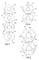
- Fig. 6, 7 and 8 three different examples of filtering paper disk bands are shown, that can be advantageously used to obtain, once bent as an accordion, a fine-filtering cartridge 16.
- the major unit that is the unit always repeated equal to itself, is composed of a pair of plane elements 61 and 62, hexagonally shaped, each one comprising a central hole and three holes 61a, 61b, 61c and 62a, 62b, 62c, placed in order to be offset after having bent the band.
- the major unit is composed of four diskettes 64, 65, 66, 67, each one equipped with a central hole and a pair of opposed holes 64a, 64b, 65a, 65b, 66a, 66b, 67a, 67b, that are offset after having bent the band.
- the major band unit is composed of a pair of diskettes 70 ⁇ and 71, each one equipped with a central hole and three offset holes 70 ⁇ a, 70 ⁇ b, 70 ⁇ c and 71a, 71b, 71c.
- Other diskette shapes are obviously possible.
- the band bent as an accordion, or zigzag-bent becomes a cylindrical crown filtering cartridge, or that approximates the cylindrical crown shape, if the band is the Fig. 6 one. It is positioned and centered in the bell 1 through the plate 41 and the base 19 of the small barrel 18.
- This type of cartridge allows keeping particles whose sizes are 3-4 »m, and therefore subjecting the lubricant to a very high filtration. It has however revealed, after a certain period of use, the inconvenience of losing compactness and becoming slack along the axial direction, with the result that the overlapped disks are spaced one from the other and the filtering effectiveness decreases.
- the property of subjecting the cartridge to the action of an on-load spring solves the above-mentioned inconvenience, since the spring allows automatically and continuously recovering the diskette spacing, with the result that compactness and filtering capacity of the cartridge are always ensured.
- This function is pointed out by the hatch-dot representation in Fig. 5, that shows the original position of the compensating spring 40 ⁇ . After a certain period of use, an axial slackening of the cartridge 16 occurs, that is however recovered by the upward thrust induced by the spring, until the position represented by the continuous-line drawing is reached.
- the general operation of the described filter is the known one of double-filtering filters with fine filtering realized in a by-pass circuit that discharges in the oil sump, at atmospheric pressure.
- the lubricant enters under pressure through the holes 8 in the cover and goes into the hollow space A between the filtering cartridges and the bell, as indicated by the arrows in Fig. 2, then it crosses in parallel the fine-filtering cartridge and the coarse-filtering one. Owing to the greater hydraulic resistance of the fine-filtering cartridge 16, only a small fraction of lubricant goes through this cartridge, while the greatest part of the lubricant goes through the coarse-filtering cartridge 14 and enters into the chamber B (Fig. 2). However, after a certain number of lubricant circulations in the filter, it can be deemed completely subjected to fine filtration too.
- the lubricant that went through the coarse-filtering cartridge 14 rises back into the chamber B through the small barrel 18, goes out from the hole 13 and is sent to the members to be lubricated.
- the two lubricant flows of fine-filtering and coarse-filtering are kept separated one from the other and with respect to the lubricant to be filtered, by the gaskets 43 and 36, in addition to the gasket 52 under the cover.
- the gasket 43 is translated with the plate 41 due to the compensating spring 40 ⁇ : it prevents lubricant blow-by between chamber A and C.
- the gasket 36 prevents instead lubricant blow-by between chambers A and B.
- the anti-clogging valve 26 is calibrated to open when the cartridge 14 is clogged and does not allow any more the lubricant to cross itself: in this way, a pressure increase in chamber A would occur, that would cause the opening of valve 26, through which the dirty lubricant would directly be discharged in the chamber B and then in the axial hole 13.
Landscapes
- Chemical & Material Sciences (AREA)
- Chemical Kinetics & Catalysis (AREA)
- Lubrication Details And Ventilation Of Internal Combustion Engines (AREA)
- Filtration Of Liquid (AREA)
- Filtering Of Dispersed Particles In Gases (AREA)
- Filtering Materials (AREA)
Claims (8)
- Filtre à double filtrage pour lubrifiants de moteur de véhicule, comprenant: une cloche cylindrique (1) fermée par un couvercle (2) contenant une cartouche de filtrage grossier (14) comportant un fond supérieur (20) et une cartouche de filtrage fin (16) placée entre la cartouche de filtrage grossier (14) et ledit couvercle, les deux présentant une forme en couronne cylindrique avec des évidements axiaux en alignement, ladite cartouche de filtrage fin (16) étant composée d'une bande de papier filtrant pliée en accordéon, ladite cartouche de filtrage fin (16) comprenant une plaque de base (41), un petit cylindre (18) avec une base (19) entre ledit couvercle (2) et ladite cartouche de filtrage fin (16), ledit petit cylindre (18) s'étendant jusqu'à l'intérieur de l'évidement axial de ladite cartouche de filtrage grossier (14), une série de trous d'entrée périphériques (6) pour le lubrifiant à filtrer, un trou de sortie central (13) pour le lubrifiant soumis au filtrage grossier et au moins un trou de sortie (12) pour le lubrifiant soumis au filtrage fin, tous prévus dans ledit couvercle (2); une paire de joints d'étanchéité (6, 10) sur le côté externe dudit couvercle; caractérisé en ce que ladite cartouche de filtrage fin (16) est soumise à une contrainte en compression en direction dudit couvercle (2) de la cloche par un ressort (40) pressé contre ladite plaque de base (41) de la cartouche elle-même, et s'appuyant contre une plaque supérieure (28) qui repose sur le fond supérieur (20) de ladite cartouche de filtrage grossier (14).
- Filtre selon la revendication 1, caractérisé en ce que ladite plaque de base (41) de la cartouche de filtrage fin (16) est formée avec un siège (42) pour loger un joint annulaire (43) établissant l'étanchéité entre ladite cartouche de filtrage fin (16) et ledit petit cylindre (18).
- Filtre selon la revendication 1, caractérisé en ce que ladite plaque supérieure (28) est fixée audit petit cylindre (18) à proximité d'un gradin (32) sur la périphérie externe dudit cylindre (18), lequel gradin (32) définit le début d'une section d'extrémité dudit cylindre (18) dont le diamètre (18') est réduit, la section de diamètre réduit (18') comprenant une partie en forme de tronc de cône (33) allant en s'élargissant en direction dudit gradin (32) et se terminant par une dent (34) pour bloquer un collier (29) de ladite plaque (28) sur ledit petit cylindre (18).
- Filtre selon la revendication 3, caractérisé en ce que ladite plaque supérieure (28) comprend une nervure supérieure (38) formant un siège pour ledit ressort de compression (40), une nervure inférieure (30) pour centrer la cartouche de filtrage grossier (14), et un siège pour un joint annulaire (36) établissant l'étanchéité entre ladite plaque supérieure (28) et ledit petit cylindre (18).
- Filtre selon la revendication 1, caractérisé en ce que ladite série de trous d'entrée (18) de lubrifiant à filtrer sont fermés le long de la direction de la décharge par un joint (52) pressé contre ledit couvercle (2) par une paire de nervures circulaires (44, 46) s'étendant à partir de la base (19) dudit petit cylindre (18), ledit joint (52) comportant une section concave apte à maintenir les trous fermés quand aucun lubrifiant n'est envoyé sous pression à l'intérieur du filtre.
- Filtre selon la revendication 5, caractérisé en ce que ledit joint (52) présente une section en forme de V dont la concavité est tournée vers ledit couvercle (2), et est équipé d'au moins un trou (55c) aligné avec ledit trou de sortie (12) du lubrifiant soumis au filtrage fin.
- Filtre selon la revendication 5, caractérisé en ce que lesdites nervures circulaires (44, 46) de ladite base (19) dudit petit cylindre (18) définissent un conduit circulaire (48) dans laquelle est prévu au moins un trou (50) communiquant avec un espace creux défini entre la partie interne de ladite cartouche de filtrage fin (16) et ledit petit cylindre (18).
- Filtre selon la revendication 1, caractérisé en ce que ledit ressort de compensation (40) est un ressort hélicoïdal en forme de tronc de cône assemblé par sa spire la plus grande contre ladite plaque de base (41) de la cartouche de filtrage fin (16).
Applications Claiming Priority (1)
| Application Number | Priority Date | Filing Date | Title |
|---|---|---|---|
| IT67904A IT1241285B (it) | 1990-11-20 | 1990-11-20 | Filtro a doppia filtrazione per lubrificanti di motori di autoveicoli, con cartuccia di filtrazione fine comprimibile. |
Publications (2)
| Publication Number | Publication Date |
|---|---|
| EP0558828A1 EP0558828A1 (fr) | 1993-09-08 |
| EP0558828B1 true EP0558828B1 (fr) | 1995-06-21 |
Family
ID=11306244
Family Applications (1)
| Application Number | Title | Priority Date | Filing Date |
|---|---|---|---|
| EP92200636A Expired - Lifetime EP0558828B1 (fr) | 1990-11-20 | 1992-03-05 | Double filtre pour lubrifiants de moteur de véhicule, avec une cartouche compressible de filtrage très fin |
Country Status (8)
| Country | Link |
|---|---|
| US (1) | US5217606A (fr) |
| EP (1) | EP0558828B1 (fr) |
| AT (1) | ATE123962T1 (fr) |
| DE (1) | DE69203090T2 (fr) |
| DK (1) | DK0558828T3 (fr) |
| ES (1) | ES2075589T3 (fr) |
| GR (1) | GR3016975T3 (fr) |
| IT (1) | IT1241285B (fr) |
Cited By (1)
| Publication number | Priority date | Publication date | Assignee | Title |
|---|---|---|---|---|
| DE202005013908U1 (de) * | 2005-09-02 | 2007-01-11 | Liebherr-Hydraulikbagger Gmbh | Vorrichtung zum Filtern von Hydrauliköl |
Families Citing this family (32)
| Publication number | Priority date | Publication date | Assignee | Title |
|---|---|---|---|---|
| FR2677893B1 (fr) * | 1991-06-20 | 1994-05-20 | Moatti Filtration | Filtre a fluide comportant deux ensembles de filtration. |
| USRE36129E (en) * | 1992-07-08 | 1999-03-09 | Dana Corporation | Air filter sealing groove |
| US5298158A (en) * | 1992-08-11 | 1994-03-29 | A. J. Amatuzio Filter Co. | Remote dual filtration system |
| DE4430341C2 (de) * | 1993-08-27 | 1997-01-09 | Hengst Walter Gmbh & Co Kg | Stützkörper für einen Fluidfilter |
| US5922199A (en) * | 1993-09-15 | 1999-07-13 | Parker Hannifin Corporation | Double pass fuel filter assembly |
| US5447627A (en) * | 1993-11-22 | 1995-09-05 | Dana Corporation | Dual-flow filter assembly with a center-tube sealing grommet |
| US5630956A (en) * | 1995-06-20 | 1997-05-20 | Certified Technologies Corporation | Oil filtering and refining device |
| US6068762A (en) * | 1995-09-29 | 2000-05-30 | Parker-Hannifin Corporation | Reusable oil filter assembly |
| DE19646248A1 (de) * | 1996-11-08 | 1998-05-14 | Aka Armaturen Rohrverschraubun | Ölfilter für Ölbrenner einer Heizungsanlage |
| US5766468A (en) * | 1997-01-06 | 1998-06-16 | Baldwin Filters, Inc. | Dual media primary/secondary fuel filter |
| DE29716366U1 (de) * | 1997-09-11 | 1997-12-11 | Ing. Walter Hengst GmbH & Co KG, 48147 Münster | Endscheibe für einen Filtereinsatz |
| DE19752376A1 (de) * | 1997-11-26 | 1999-05-27 | Mann & Hummel Filter | Filter |
| US6254772B1 (en) * | 1998-01-15 | 2001-07-03 | Yiu Chau Chau | Backwashable filtration system |
| US6413290B1 (en) | 1999-12-06 | 2002-07-02 | Thomas J. Gruber | Filter cartridge with detection device |
| GB2359763B (en) * | 2000-02-19 | 2002-07-17 | Alan Philip Roper | Dual flow filter |
| EP1199093A1 (fr) * | 2000-10-18 | 2002-04-24 | ARGO GmbH für Fluidtechnik | Elément filtrant |
| DE10124476B4 (de) * | 2001-05-19 | 2014-05-28 | Man Diesel & Turbo, Filial Af Man Diesel & Turbo Se, Tyskland | Ölversorgungseinrichtung für einen Großdieselmotor |
| US6740236B2 (en) | 2001-09-25 | 2004-05-25 | Kuss Corporation | Fuel filter assembly having a conductive spring |
| US7235177B2 (en) * | 2003-04-23 | 2007-06-26 | Fleetguard, Inc. | Integral air/oil coalescer for a centrifuge |
| US7208084B2 (en) * | 2004-09-07 | 2007-04-24 | T.F.H. Publications, Inc. | Modular aquarium filter |
| RU2294440C1 (ru) * | 2005-09-26 | 2007-02-27 | Евгений Владимирович Морозов | Двухсекционный фильтрующий элемент масляного фильтра |
| US8293103B2 (en) | 2005-12-08 | 2012-10-23 | Donaldson Company, Inc. | Spin-on filter assembly and methods |
| BRPI0707339A2 (pt) * | 2006-01-30 | 2011-05-03 | Donaldson Co Inc | arranjo de filtro e métodos |
| US20090314727A1 (en) * | 2006-02-07 | 2009-12-24 | Donaldson Company, Inc. | Filter arrangement and methods |
| US8220640B2 (en) * | 2007-07-23 | 2012-07-17 | Cummins Filtration Ip, Inc. | Stack-disk filter cartridge |
| EP2938419B1 (fr) * | 2012-12-28 | 2020-08-05 | Vestas Wind Systems A/S | Éolienne comprenant un système à base de fluide |
| CN103291413B (zh) * | 2013-04-12 | 2016-06-01 | 宁波正利汽车部件有限公司 | 一种机油滤清器 |
| DE102013019887A1 (de) * | 2013-11-28 | 2015-05-28 | Mann + Hummel Gmbh | Filterelement und Filtersystem mit Nebenstromfilterung |
| EP3277358B1 (fr) | 2015-03-31 | 2019-05-08 | Koninklijke Philips N.V. | Système de support de pression |
| CN104806394B (zh) * | 2015-04-10 | 2017-04-05 | 苏州达菲特过滤技术股份有限公司 | 一种紧凑型多层星型折纸滤清器 |
| DE102016201334A1 (de) | 2016-01-29 | 2017-08-03 | Robert Bosch Gmbh | Filterelement |
| CN119113609B (zh) * | 2024-11-14 | 2025-03-18 | 湘西弘湘醋业有限责任公司 | 一种酿醋生产的杂质过滤装置 |
Family Cites Families (10)
| Publication number | Priority date | Publication date | Assignee | Title |
|---|---|---|---|---|
| GB608531A (en) * | 1945-05-12 | 1948-09-16 | Fram Corp | Improvements relating to filter elements for use in the filtration of liquids |
| CH306629A (de) * | 1951-10-04 | 1955-04-30 | Gmbh Robert Bosch | Zellenfilter. |
| US2748949A (en) * | 1954-09-28 | 1956-06-05 | Fram Corp | Combined full-flow and part-flow oil filter |
| US3268077A (en) * | 1963-04-10 | 1966-08-23 | Chrysler Corp | Dual element, dual valve filter |
| NL130139C (fr) * | 1963-07-26 | |||
| US3353680A (en) * | 1964-07-06 | 1967-11-21 | Walker Mfg Co | Dual element parallel flow filter assembly |
| GB1604832A (en) * | 1978-05-31 | 1981-12-16 | Fram Corp | Apparatus for filtering fluids |
| IT1165502B (it) * | 1980-01-11 | 1987-04-22 | Tecnocar Spa | Filtro per lubrificanti di motori a combustione interna particolarmente per autoveicoli |
| US4738776A (en) * | 1986-05-23 | 1988-04-19 | Cummins Engine Company, Inc. | Lubricant filter assembly |
| IT215033Z2 (it) * | 1988-09-09 | 1990-07-30 | Tecnocar Spa | Filtro a doppia filtrazione perfezionato per olio lubrificante di motori a combustione interna di autoveicoli |
-
1990
- 1990-11-20 IT IT67904A patent/IT1241285B/it active IP Right Grant
-
1992
- 1992-03-02 US US07/844,139 patent/US5217606A/en not_active Expired - Fee Related
- 1992-03-05 AT AT92200636T patent/ATE123962T1/de not_active IP Right Cessation
- 1992-03-05 DE DE69203090T patent/DE69203090T2/de not_active Expired - Fee Related
- 1992-03-05 DK DK92200636.6T patent/DK0558828T3/da active
- 1992-03-05 EP EP92200636A patent/EP0558828B1/fr not_active Expired - Lifetime
- 1992-03-05 ES ES92200636T patent/ES2075589T3/es not_active Expired - Lifetime
-
1995
- 1995-08-02 GR GR950401527T patent/GR3016975T3/el unknown
Cited By (1)
| Publication number | Priority date | Publication date | Assignee | Title |
|---|---|---|---|---|
| DE202005013908U1 (de) * | 2005-09-02 | 2007-01-11 | Liebherr-Hydraulikbagger Gmbh | Vorrichtung zum Filtern von Hydrauliköl |
Also Published As
| Publication number | Publication date |
|---|---|
| DK0558828T3 (da) | 1995-11-06 |
| EP0558828A1 (fr) | 1993-09-08 |
| DE69203090T2 (de) | 1996-02-15 |
| ES2075589T3 (es) | 1995-10-01 |
| IT9067904A0 (it) | 1990-11-20 |
| US5217606A (en) | 1993-06-08 |
| GR3016975T3 (en) | 1995-11-30 |
| DE69203090D1 (de) | 1995-07-27 |
| IT1241285B (it) | 1993-12-29 |
| IT9067904A1 (it) | 1992-05-20 |
| ATE123962T1 (de) | 1995-07-15 |
Similar Documents
| Publication | Publication Date | Title |
|---|---|---|
| EP0558828B1 (fr) | Double filtre pour lubrifiants de moteur de véhicule, avec une cartouche compressible de filtrage très fin | |
| US3232437A (en) | Spin-on filter cartridge | |
| US3859216A (en) | Filter assembly | |
| US3985657A (en) | Fluid filter cartridge | |
| US6177003B1 (en) | Filter with safety element for filtering engine oil | |
| MXPA04008896A (es) | Ensamble de flitro de aceite. | |
| EP0362554B1 (fr) | Double filtre d'huile pour moteurs à combustion interne pour voitures | |
| GB2389322A (en) | Non-metallic dual filter cartridge | |
| US6096199A (en) | Oil filter cartridge with temperature sensitive bypass valve | |
| CA2001049C (fr) | Filtre d'huile | |
| KR19990071579A (ko) | 유체 필터용 필터 요소 | |
| KR860001707B1 (ko) | 오일 휠터 | |
| US3557957A (en) | Filter assembly having a two-way bypass valve therein | |
| US6270660B1 (en) | Flow inverter for filters | |
| US5833843A (en) | Anti-drain back/pressure relieved filter cartridges | |
| US3633750A (en) | Filter element valve means | |
| GB2226254A (en) | Filter element | |
| US6027640A (en) | Anti-drain back/pressure relieved filter cartridges | |
| US5679244A (en) | Spin-on liquid filter with unique straight through flow path | |
| JPH10159530A (ja) | オイルフィルターのリリーフ弁構造 | |
| US3380593A (en) | Twist-on, axial flow filter element | |
| US4517083A (en) | Filter device having relief valve for use in power steering system | |
| EP0439901A1 (fr) | Filtre à huile | |
| US6892759B2 (en) | Valve having at least one screen | |
| JPH05285311A (ja) | 自動車エンジンの潤滑油用の二重ろ過フィルタ |
Legal Events
| Date | Code | Title | Description |
|---|---|---|---|
| PUAI | Public reference made under article 153(3) epc to a published international application that has entered the european phase |
Free format text: ORIGINAL CODE: 0009012 |
|
| AK | Designated contracting states |
Kind code of ref document: A1 Designated state(s): AT BE CH DE DK ES FR GB GR IT LI LU MC NL PT SE |
|
| 17P | Request for examination filed |
Effective date: 19931210 |
|
| 17Q | First examination report despatched |
Effective date: 19941111 |
|
| GRAA | (expected) grant |
Free format text: ORIGINAL CODE: 0009210 |
|
| ITF | It: translation for a ep patent filed | ||
| RAP1 | Party data changed (applicant data changed or rights of an application transferred) |
Owner name: TECNOCAR S.R.L. |
|
| AK | Designated contracting states |
Kind code of ref document: B1 Designated state(s): AT BE CH DE DK ES FR GB GR IT LI LU MC NL PT SE |
|
| REF | Corresponds to: |
Ref document number: 123962 Country of ref document: AT Date of ref document: 19950715 Kind code of ref document: T |
|
| REF | Corresponds to: |
Ref document number: 69203090 Country of ref document: DE Date of ref document: 19950727 |
|
| REG | Reference to a national code |
Ref country code: ES Ref legal event code: FG2A Ref document number: 2075589 Country of ref document: ES Kind code of ref document: T3 |
|
| ET | Fr: translation filed | ||
| SC4A | Pt: translation is available |
Free format text: 950628 AVAILABILITY OF NATIONAL TRANSLATION |
|
| REG | Reference to a national code |
Ref country code: GR Ref legal event code: FG4A Free format text: 3016975 |
|
| REG | Reference to a national code |
Ref country code: DK Ref legal event code: T3 |
|
| PGFP | Annual fee paid to national office [announced via postgrant information from national office to epo] |
Ref country code: MC Payment date: 19960228 Year of fee payment: 5 Ref country code: GR Payment date: 19960228 Year of fee payment: 5 Ref country code: GB Payment date: 19960228 Year of fee payment: 5 Ref country code: FR Payment date: 19960228 Year of fee payment: 5 |
|
| PGFP | Annual fee paid to national office [announced via postgrant information from national office to epo] |
Ref country code: LU Payment date: 19960301 Year of fee payment: 5 |
|
| PGFP | Annual fee paid to national office [announced via postgrant information from national office to epo] |
Ref country code: BE Payment date: 19960304 Year of fee payment: 5 |
|
| PGFP | Annual fee paid to national office [announced via postgrant information from national office to epo] |
Ref country code: CH Payment date: 19960305 Year of fee payment: 5 |
|
| PGFP | Annual fee paid to national office [announced via postgrant information from national office to epo] |
Ref country code: ES Payment date: 19960311 Year of fee payment: 5 |
|
| PGFP | Annual fee paid to national office [announced via postgrant information from national office to epo] |
Ref country code: DE Payment date: 19960318 Year of fee payment: 5 |
|
| PGFP | Annual fee paid to national office [announced via postgrant information from national office to epo] |
Ref country code: PT Payment date: 19960320 Year of fee payment: 5 |
|
| PGFP | Annual fee paid to national office [announced via postgrant information from national office to epo] |
Ref country code: DK Payment date: 19960328 Year of fee payment: 5 Ref country code: AT Payment date: 19960328 Year of fee payment: 5 |
|
| PGFP | Annual fee paid to national office [announced via postgrant information from national office to epo] |
Ref country code: SE Payment date: 19960329 Year of fee payment: 5 |
|
| PGFP | Annual fee paid to national office [announced via postgrant information from national office to epo] |
Ref country code: NL Payment date: 19960331 Year of fee payment: 5 |
|
| PLBE | No opposition filed within time limit |
Free format text: ORIGINAL CODE: 0009261 |
|
| STAA | Information on the status of an ep patent application or granted ep patent |
Free format text: STATUS: NO OPPOSITION FILED WITHIN TIME LIMIT |
|
| 26N | No opposition filed | ||
| PG25 | Lapsed in a contracting state [announced via postgrant information from national office to epo] |
Ref country code: LU Free format text: LAPSE BECAUSE OF NON-PAYMENT OF DUE FEES Effective date: 19970305 Ref country code: GB Effective date: 19970305 Ref country code: DK Effective date: 19970305 Ref country code: AT Effective date: 19970305 |
|
| REG | Reference to a national code |
Ref country code: DK Ref legal event code: EBP |
|
| PG25 | Lapsed in a contracting state [announced via postgrant information from national office to epo] |
Ref country code: SE Effective date: 19970306 Ref country code: ES Free format text: LAPSE BECAUSE OF NON-PAYMENT OF DUE FEES Effective date: 19970306 |
|
| PG25 | Lapsed in a contracting state [announced via postgrant information from national office to epo] |
Ref country code: LI Effective date: 19970331 Ref country code: CH Effective date: 19970331 Ref country code: BE Effective date: 19970331 |
|
| BERE | Be: lapsed |
Owner name: TECNOCAR S.R.L. Effective date: 19970331 |
|
| PG25 | Lapsed in a contracting state [announced via postgrant information from national office to epo] |
Ref country code: PT Effective date: 19970930 Ref country code: MC Effective date: 19970930 Ref country code: GR Free format text: THE PATENT HAS BEEN ANNULLED BY A DECISION OF A NATIONAL AUTHORITY Effective date: 19970930 |
|
| PG25 | Lapsed in a contracting state [announced via postgrant information from national office to epo] |
Ref country code: NL Effective date: 19971001 |
|
| GBPC | Gb: european patent ceased through non-payment of renewal fee |
Effective date: 19970305 |
|
| REG | Reference to a national code |
Ref country code: GR Ref legal event code: MM2A Free format text: 3016975 |
|
| REG | Reference to a national code |
Ref country code: CH Ref legal event code: PL |
|
| PG25 | Lapsed in a contracting state [announced via postgrant information from national office to epo] |
Ref country code: FR Free format text: LAPSE BECAUSE OF NON-PAYMENT OF DUE FEES Effective date: 19971128 |
|
| NLV4 | Nl: lapsed or anulled due to non-payment of the annual fee |
Effective date: 19971001 |
|
| PG25 | Lapsed in a contracting state [announced via postgrant information from national office to epo] |
Ref country code: DE Effective date: 19971202 |
|
| EUG | Se: european patent has lapsed |
Ref document number: 92200636.6 |
|
| REG | Reference to a national code |
Ref country code: FR Ref legal event code: ST Ref country code: PT Ref legal event code: MM4A Free format text: LAPSE DUE TO NON-PAYMENT OF FEES Effective date: 19970930 |
|
| REG | Reference to a national code |
Ref country code: ES Ref legal event code: FD2A Effective date: 19990201 |
|
| PG25 | Lapsed in a contracting state [announced via postgrant information from national office to epo] |
Ref country code: IT Free format text: LAPSE BECAUSE OF NON-PAYMENT OF DUE FEES Effective date: 20050305 |