EP0558845A1 - Système de fusion de la neige et de la glace et unité de chauffage pour celui-ci - Google Patents
Système de fusion de la neige et de la glace et unité de chauffage pour celui-ci Download PDFInfo
- Publication number
- EP0558845A1 EP0558845A1 EP92304631A EP92304631A EP0558845A1 EP 0558845 A1 EP0558845 A1 EP 0558845A1 EP 92304631 A EP92304631 A EP 92304631A EP 92304631 A EP92304631 A EP 92304631A EP 0558845 A1 EP0558845 A1 EP 0558845A1
- Authority
- EP
- European Patent Office
- Prior art keywords
- heating unit
- snow
- heating element
- melting system
- ice
- Prior art date
- Legal status (The legal status is an assumption and is not a legal conclusion. Google has not performed a legal analysis and makes no representation as to the accuracy of the status listed.)
- Granted
Links
- 238000010438 heat treatment Methods 0.000 title claims abstract description 76
- 238000002844 melting Methods 0.000 title claims description 16
- 230000008018 melting Effects 0.000 title claims description 16
- 239000000463 material Substances 0.000 claims abstract description 26
- 229910052782 aluminium Inorganic materials 0.000 claims abstract description 16
- XAGFODPZIPBFFR-UHFFFAOYSA-N aluminium Chemical compound [Al] XAGFODPZIPBFFR-UHFFFAOYSA-N 0.000 claims abstract description 16
- 239000004744 fabric Substances 0.000 claims abstract description 12
- 229910052751 metal Inorganic materials 0.000 claims abstract description 12
- 239000002184 metal Substances 0.000 claims abstract description 12
- 239000004020 conductor Substances 0.000 claims description 3
- 125000000391 vinyl group Chemical group [H]C([*])=C([H])[H] 0.000 claims description 3
- 229920002554 vinyl polymer Polymers 0.000 claims description 3
- 239000010426 asphalt Substances 0.000 abstract description 13
- 239000011248 coating agent Substances 0.000 abstract description 7
- 238000000576 coating method Methods 0.000 abstract description 7
- 239000012799 electrically-conductive coating Substances 0.000 abstract description 3
- 239000008187 granular material Substances 0.000 abstract description 2
- 239000002893 slag Substances 0.000 abstract description 2
- XEEYBQQBJWHFJM-UHFFFAOYSA-N Iron Chemical compound [Fe] XEEYBQQBJWHFJM-UHFFFAOYSA-N 0.000 description 8
- 238000000034 method Methods 0.000 description 6
- 238000010276 construction Methods 0.000 description 5
- 239000002987 primer (paints) Substances 0.000 description 5
- 239000011810 insulating material Substances 0.000 description 4
- 229910052742 iron Inorganic materials 0.000 description 4
- 239000004065 semiconductor Substances 0.000 description 3
- 239000000126 substance Substances 0.000 description 3
- OKTJSMMVPCPJKN-UHFFFAOYSA-N Carbon Chemical compound [C] OKTJSMMVPCPJKN-UHFFFAOYSA-N 0.000 description 2
- 229920000742 Cotton Polymers 0.000 description 2
- 229910001111 Fine metal Inorganic materials 0.000 description 2
- 229910002090 carbon oxide Inorganic materials 0.000 description 2
- BVNSZWBIJTVRJP-UHFFFAOYSA-N chloroethene;ethyl carbamate Chemical compound ClC=C.CCOC(N)=O BVNSZWBIJTVRJP-UHFFFAOYSA-N 0.000 description 2
- 230000005611 electricity Effects 0.000 description 2
- 239000006260 foam Substances 0.000 description 2
- 229910044991 metal oxide Inorganic materials 0.000 description 2
- 150000004706 metal oxides Chemical class 0.000 description 2
- 239000000203 mixture Substances 0.000 description 2
- 239000011347 resin Substances 0.000 description 2
- 229920005989 resin Polymers 0.000 description 2
- RYGMFSIKBFXOCR-UHFFFAOYSA-N Copper Chemical compound [Cu] RYGMFSIKBFXOCR-UHFFFAOYSA-N 0.000 description 1
- 238000009825 accumulation Methods 0.000 description 1
- 230000000386 athletic effect Effects 0.000 description 1
- 229910052802 copper Inorganic materials 0.000 description 1
- 239000010949 copper Substances 0.000 description 1
- 230000007797 corrosion Effects 0.000 description 1
- 238000005260 corrosion Methods 0.000 description 1
- 230000001627 detrimental effect Effects 0.000 description 1
- 230000000694 effects Effects 0.000 description 1
- 238000005485 electric heating Methods 0.000 description 1
- 238000009429 electrical wiring Methods 0.000 description 1
- 230000002349 favourable effect Effects 0.000 description 1
- 230000008014 freezing Effects 0.000 description 1
- 238000007710 freezing Methods 0.000 description 1
- 238000009434 installation Methods 0.000 description 1
- 230000007257 malfunction Effects 0.000 description 1
- 238000004519 manufacturing process Methods 0.000 description 1
- 150000002739 metals Chemical class 0.000 description 1
- 238000003825 pressing Methods 0.000 description 1
- 238000005096 rolling process Methods 0.000 description 1
- 238000003892 spreading Methods 0.000 description 1
Images

Classifications
-
- E—FIXED CONSTRUCTIONS
- E01—CONSTRUCTION OF ROADS, RAILWAYS, OR BRIDGES
- E01C—CONSTRUCTION OF, OR SURFACES FOR, ROADS, SPORTS GROUNDS, OR THE LIKE; MACHINES OR AUXILIARY TOOLS FOR CONSTRUCTION OR REPAIR
- E01C11/00—Details of pavings
- E01C11/24—Methods or arrangements for preventing slipperiness or protecting against influences of the weather
- E01C11/26—Permanently installed heating or blowing devices ; Mounting thereof
- E01C11/265—Embedded electrical heating elements ; Mounting thereof
-
- E—FIXED CONSTRUCTIONS
- E04—BUILDING
- E04D—ROOF COVERINGS; SKY-LIGHTS; GUTTERS; ROOF-WORKING TOOLS
- E04D13/00—Special arrangements or devices in connection with roof coverings; Protection against birds; Roof drainage ; Sky-lights
- E04D13/10—Snow traps ; Removing snow from roofs; Snow melters
- E04D13/103—De-icing devices or snow melters
Definitions
- the present invention relates to an ice and snow melting system for melting ice or snow on exposed surfaces liable to receive snow or ice.
- the system is useful for vehicle carrying surfaces such as roads where it can help prevent accidents involving vehicles and aircraft travelling on roads or runways due to slipping caused by snow by removing said snow.
- the system involves embedding a heating unit incorporating a surface heating element beneath the surface of the ground to melt the snow.
- An object of the present invention is to provide an ice and snow melting system, in which the heating element is less open to damage by vehicles travelling on roads or aircraft taking off and landing on runways, and which does not affect the service life of the road.
- the invention therefore provides a snow melting system for melting ice and snow on roads or exposed surfaces liable to receive snow or ice.
- This snow melting system is useful in relation to any civil engineering structure.
- the system includes a heating unit which is embedded below the surface of the road or exposed surface and which comprises a surface heating element enclosed in a tar-based moisture-proof sheet material.
- the heating unit itself is also provided and it comprises a surface heating element positioned between metal plates above and below, and adapted to be embedded beneath a surface.
- the surface heating element is of lamellar construction.
- the surface heating element may be a cloth base coated with an electrically conductive material.
- a further layer of vinyl sheet is also laminated to the surface of the conductive layer.
- the cloth base is cotton with other fabrics and has a size of around 4 square metres.
- the electrodes of the surface heating element are preferably fine metal wires e.g. soft iron, which are embedded at opposite edges of the cloth base.
- the heating unit which comprises the surface heating element involves the surface heating element positioned or sandwiched between aluminum plates above and below, although other metals are also useful.
- Metal plates such as those of copper or iron may be used in place of aluminum, and different metal plates may be used for the upper and lower surfaces to prevent electrolytic corrosion.
- the thickness of the plates is preferably in a range of 0.1 to 5 mm.
- the electrically conductive coating material comprises a solution of a resin such as urethane vinyl chloride, the solution containing dissolved semiconductor substances such as carbon or metal oxide.
- the top and bottom of said heating element is wrapped or enclosed in a tar-based moisture-proof sheet material that is adhered around it.
- the foundation for embedding the above-mentioned heating unit beneath the surface of the ground is first sufficiently steam rolled e.g. by a steam roller so that there are no irregularities in the asphalt beneath the ground as well as in the concrete base layer. Then, primer is applied, the heating unit is installed at the prescribed location and wiring connections are made.
- the surface heating element is of a cloth and coating type
- those factors which are cause for the greatest apprehension when embedding the heating element beneath the surface of the ground are whether or not said heating element will be able to withstand load pressure, as well as the risk of the crushed stones blended into the asphalt and concrete eating into the surface heating element.
- aluminum plates are installed above and below the surface heating element.
- the upper aluminum plate gradually transfers the heat radiated from the heating element to the tar-based moisture-proof sheet by temporarily accumulating said heat, and then transferring said heat to the highly thermal conductive fine granular asphalt that comprises the surface material in order to raise the temperature of the ground surface.
- the lower aluminum plate demonstrates effects which suppress the transfer of heat radiated from the heating element.
- thermal efficiency is extremely favourable allowing a saving of roughly 40% less electrical power to maintain the surface temperature at a constant level than in the case of a heating element in which electric heating cords simply run through said heating element in zig-zag fashion.
- the surface temperature in the case of implementing the heating element of the present invention in the manner described above demonstrated a temperature of +0.6 degrees Celsius.
- a temperature of +8.0 degrees Celsius was attained in the case of the present invention.
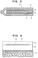
- Fig. 3 is a schematic drawing which indicates a portion of the cross-section of heating unit 4.
- the actual heating unit is a thin object free of any lamellar space.
- the surface heating element is indicated by the reference numeral 1.
- the surface heating element is a piece of cloth, having an area of about 4 square metres.
- the cloth is a mixture of cotton and other materials.
- fine metal wires of soft iron are embedded in a 20 mm wide zone to act as electrodes.
- An electrically conductive coating material is then coated onto both surfaces of the cloth base.
- the conductive coating is a solution of a resin such as urethane vinyl chloride in which semi-conductor substances such as carbon or metal oxide are dissolved.
- the cloth base After coating with the conductive material, the cloth base is further laminated with a vinyl sheet.
- electricity is applied to the electrodes of this surface heating element, the semi-conductor substances contained in the conductive coating material generate heat.
- the heating element 1 is positioned between aluminum plates 2 which are adhered above and below the heating element.
- a tar-based moisture-proof sheet material 3 is adhered around the heating element and plates to envelope them.
- cab-tyre cables which carry electricity to the electrode wires are also enveloped by the moisture-proof sheet material.
- the heating unit is therefore sealed within the moisture-proof material.
- the thickness of the aluminum (or other metal) plates differs according to the type of surface material 5 on the road. For example if the surface material is fine particulate asphalt then an aluminum sheet of thickness 0.1 mm-0.3 mm is sufficient. If the surface material is ordinary concrete, then an aluminum plate of thickness 1 mm-1.5 mm may be used. When an aluminum sheet of thickness 0.1 mm-0.3 mm is used, the heating element may be rolled up.
- Figure 2 is a cross-sectional side view of the foundation in which heating unit 4 is embedded.
- the cobblestone layer 78 is covered over the bottom using a procedure similar to routine construction procedures, the asphalt base 6 on top of said cobblestone layer 7 is steam rolled more carefully than in the case of routine construction procedures because it is critically important that the surface be flat and completely free of irregularities in comparison to routine construction procedures.
- primer is coated onto said asphalt base 6 after which the heating unit 4 is installed at the prescribed location followed by wiring. Wiring work is performed in accordance with routine electrical wiring procedures, with wiring performed from said heating unit 4 to a control box using cab-tyre cables and conduit.
- the control box is equipped with devices including an automatic operating unit activated by a snowfall sensor, and safety devices including a thermostat.
- the ground wire is taken off from aluminum plates 2. Following wiring work, an additional coating of primer is applied on the upper surface of heating unit 4 followed by the spreading of fine granular asphalt having a high degree of thermal conductivity to a thickness of 50-60 mm on top of said primer coating to function as surface material 5. Steam rolling, pressing and so on using a compactor or roller, etc. are then performed in accordance with conventional construction procedures.
- the roadway portion is of a structure nearly identical to that of ordinary road paving, being comprised of asphalt and concrete without using foam heating insulating materials having a low level of strength, there is no reduction in the strength of the road paving. Consequently, although aluminum plates are used as heat insulating materials beneath the heating unit, the action of those plates as heat insulating materials is not great. Instead, it was possible to obtain a higher degree of thermal efficiency in comparison to using foam heat insulating materials by using a material having a higher degree of thermal conductivity than ordinary paving material for the surface material. In addition, the present invention also offers the advantage of suffering fewer malfunctions as a result of the surface heating element being positioned between metal plates on both sides.
- roadways and runways embedded with the surface heating element of the present invention are continuously kept free of snow and ice, thus nearly completely eliminating accidents caused by snow, including slipping and leaving of the roadway of vehicles crossing said roadways, thereby allowing the securing of safety and accuracy of drivers.
- the present invention is not limited to use in only roadways and runways, but is also a system that can be widely applied in building roofs, athletic grounds and other locations at which removal of snow is required.
Landscapes
- Engineering & Computer Science (AREA)
- Architecture (AREA)
- Civil Engineering (AREA)
- Structural Engineering (AREA)
- Road Paving Structures (AREA)
- Surface Heating Bodies (AREA)
- Train Traffic Observation, Control, And Security (AREA)
- Buildings Adapted To Withstand Abnormal External Influences (AREA)
Applications Claiming Priority (2)
| Application Number | Priority Date | Filing Date | Title |
|---|---|---|---|
| JP92476/92 | 1992-02-28 | ||
| JP4092476A JP2632470B2 (ja) | 1992-02-28 | 1992-02-28 | 面状発熱体による踏切の融雪構造 |
Publications (2)
| Publication Number | Publication Date |
|---|---|
| EP0558845A1 true EP0558845A1 (fr) | 1993-09-08 |
| EP0558845B1 EP0558845B1 (fr) | 1996-09-11 |
Family
ID=14055370
Family Applications (1)
| Application Number | Title | Priority Date | Filing Date |
|---|---|---|---|
| EP92304631A Expired - Lifetime EP0558845B1 (fr) | 1992-02-28 | 1992-05-21 | Système de fusion de la neige et de la glace et unité de chauffage pour celui-ci |
Country Status (7)
| Country | Link |
|---|---|
| US (1) | US5605418A (fr) |
| EP (1) | EP0558845B1 (fr) |
| JP (1) | JP2632470B2 (fr) |
| AT (1) | ATE142729T1 (fr) |
| CA (1) | CA2069238C (fr) |
| DE (1) | DE69213707T2 (fr) |
| DK (1) | DK0558845T3 (fr) |
Cited By (2)
| Publication number | Priority date | Publication date | Assignee | Title |
|---|---|---|---|---|
| EP0913523A1 (fr) * | 1997-10-28 | 1999-05-06 | FlowTex Technologie GmbH & Co. KG | Piste de roulement d'un aéroport thermo-réglable et procédé pour adapter une piste de roulement existante |
| EP0887471A3 (fr) * | 1997-06-23 | 2000-03-01 | Kuniaki Yakushinji | Bloc pour la lutte contre les mauvaises herbes et structure de lutte pour blocs |
Families Citing this family (24)
| Publication number | Priority date | Publication date | Assignee | Title |
|---|---|---|---|---|
| US5966502A (en) * | 1997-08-13 | 1999-10-12 | Clearpath, Inc. | Apparatus for melting snow and ice |
| US5948299A (en) * | 1998-07-02 | 1999-09-07 | Scalia; Henry | Portable snow melting device |
| US6180929B1 (en) | 1998-08-06 | 2001-01-30 | Clearpath, Inc. | Heating pad apparatus adapted for outdoor use |
| US6184496B1 (en) * | 1998-08-06 | 2001-02-06 | Clearpath, Inc. | Driveway, walkway and roof snow and ice melting mat |
| US20080196429A1 (en) * | 2002-02-11 | 2008-08-21 | The Trustees Of Dartmouth College | Pulse Electrothermal And Heat-Storage Ice Detachment Apparatus And Method |
| US7638735B2 (en) * | 2002-02-11 | 2009-12-29 | The Trustees Of Dartmouth College | Pulse electrothermal and heat-storage ice detachment apparatus and methods |
| US8405002B2 (en) * | 2002-02-11 | 2013-03-26 | The Trustees Of Dartmouth College | Pulse electrothermal mold release icemaker with safety baffles for refrigerator |
| US20090235681A1 (en) * | 2002-02-11 | 2009-09-24 | The Trustees Of Dartmouth College | Pulse Electrothermal Mold Release Icemaker For Refrigerator Having Interlock Closure And Baffle For Safety |
| US20080223842A1 (en) * | 2002-02-11 | 2008-09-18 | The Trustees Of Dartmouth College | Systems And Methods For Windshield Deicing |
| AU2003213017A1 (en) * | 2002-02-11 | 2003-09-04 | The Trustees Of Dartmouth College | Systems and methods for modifying an ice-to-object interface |
| US7703300B2 (en) * | 2004-06-22 | 2010-04-27 | The Trustees Of Dartmouth College | Pulse systems and methods for detaching ice |
| US7358460B2 (en) * | 2004-12-22 | 2008-04-15 | Hoffman William H | Deployment system for thermal radiating materials |
| EP2032916A2 (fr) * | 2006-05-22 | 2009-03-11 | The Trustees of Dartmouth College | Dégivrage électrothermique par impulsions de formes complexes |
| KR20110103947A (ko) | 2008-11-05 | 2011-09-21 | 더 트러스티즈 오브 다트마우스 칼리지 | 진동―전열 제상부를 구비한 냉매 증발기 |
| WO2010080549A1 (fr) * | 2008-12-17 | 2010-07-15 | Hulen Michael S | Systèmes et procédés pour faire fonctionner un équipement environnemental utilisant de l'énergie obtenue à partir de couvertures de surface manufacturées présentant des améliorations en termes d'efficacité |
| US8931296B2 (en) | 2009-11-23 | 2015-01-13 | John S. Chen | System and method for energy-saving inductive heating of evaporators and other heat-exchangers |
| JP5334266B2 (ja) * | 2010-05-18 | 2013-11-06 | 株式会社ホクスイ設計コンサル | 空気吹出型路面融雪システム |
| WO2013116832A1 (fr) * | 2012-02-02 | 2013-08-08 | Engineered Plastics Inc. | Surface résistante au gel |
| CN103216049A (zh) * | 2013-03-23 | 2013-07-24 | 梁艳芬 | 一种新型融雪器 |
| US10398138B2 (en) * | 2014-04-08 | 2019-09-03 | Lampman Wildlife Management Services Limited | Wildlife exclusion composition and assembly |
| US10988904B2 (en) | 2016-08-18 | 2021-04-27 | Ian R. Cooke | Snow and ice melting device, system and corresponding methods |
| WO2018064757A1 (fr) * | 2016-10-05 | 2018-04-12 | Betterfrost Technologies Inc. | Bobine d'évaporateur à auto-dégivrage haute-fréquence |
| CN109098362B (zh) * | 2018-09-25 | 2024-06-25 | 浙江明烁节能科技股份有限公司 | 用于融化冰雪的柔性卷材贴及其冰雪融化系统、方法 |
| CN115404739B (zh) * | 2022-09-30 | 2023-08-15 | 湖北工业大学 | 一种道路或机场预埋管布置结构及进行温控和拆除的方法 |
Citations (4)
| Publication number | Priority date | Publication date | Assignee | Title |
|---|---|---|---|---|
| BE704645A (fr) * | 1967-10-04 | 1968-04-04 | Acec | Procédé de fabrication de troncons de route chauffés |
| DE1459745A1 (de) * | 1963-05-31 | 1968-12-12 | Benno Palatini | Einrichtungen zum elektrischen Beheizen von flaechenhaft ausgedehnten Baukoerpern |
| CH534997A (de) * | 1971-07-12 | 1973-03-15 | Electrofina Ag | Heizbares Flächenelement |
| CH579859A5 (en) * | 1974-12-19 | 1976-09-15 | Windisch Josef Gottfried | Electric surface heating element - has resistance wires positioned in plastics grid enclosed between two plastics sheets |
Family Cites Families (15)
| Publication number | Priority date | Publication date | Assignee | Title |
|---|---|---|---|---|
| US2889445A (en) * | 1955-03-28 | 1959-06-02 | Herman B Wolf | Electrically heated mat |
| US2851992A (en) * | 1956-09-05 | 1958-09-16 | Radiant Products Inc | Brooder and heating unit therefor |
| US2952001A (en) * | 1958-08-04 | 1960-09-06 | Linton Summit Coal Company Inc | Electrical heating tape and method of making |
| AT251631B (de) * | 1963-09-16 | 1967-01-10 | Herbert Dipl Ing Pferschy | Vorrichtung zum Beheizen von Bodenflächen |
| US3236991A (en) * | 1963-12-18 | 1966-02-22 | William P Graham | Sidewalk heating means for melting snow |
| US3791443A (en) * | 1971-12-13 | 1974-02-12 | Atlantic Richfield Co | Foundation for construction on frozen substrata |
| JPS5110892B2 (fr) * | 1972-04-06 | 1976-04-07 | ||
| US4110597A (en) * | 1976-05-05 | 1978-08-29 | Elmore Theodore V | Heating device |
| US4141187A (en) * | 1977-01-28 | 1979-02-27 | Graves Robert J | Roofing and surfacing material and method |
| SE424109B (sv) * | 1978-11-22 | 1982-06-28 | Foerenade Fabriksverken | Metod och anordning for reglering av temperaturen i asfalt- eller betongkroppar |
| DE3433702A1 (de) * | 1984-09-13 | 1986-03-20 | Buchtal Gmbh, 8472 Schwarzenfeld | Wand-, decken- und/oder bodenausbildung sowie verfahren zu ihrer herstellung |
| JPS6276494U (fr) * | 1985-10-31 | 1987-05-16 | ||
| US4693300A (en) * | 1986-08-04 | 1987-09-15 | Nippon Flute, Co. | Method and apparatus for sprinklerless snow control |
| US4937435A (en) * | 1987-12-14 | 1990-06-26 | Thermon Manufacturing Company | Flexible electric heating pad using PTC ceramic thermistor chip heating elements |
| US4919744A (en) * | 1988-09-30 | 1990-04-24 | Raychem Corporation | Method of making a flexible heater comprising a conductive polymer |
-
1992
- 1992-02-28 JP JP4092476A patent/JP2632470B2/ja not_active Expired - Lifetime
- 1992-05-21 AT AT92304631T patent/ATE142729T1/de not_active IP Right Cessation
- 1992-05-21 DE DE69213707T patent/DE69213707T2/de not_active Expired - Fee Related
- 1992-05-21 DK DK92304631.2T patent/DK0558845T3/da active
- 1992-05-21 EP EP92304631A patent/EP0558845B1/fr not_active Expired - Lifetime
- 1992-05-22 CA CA002069238A patent/CA2069238C/fr not_active Expired - Fee Related
-
1993
- 1993-09-20 US US08/123,044 patent/US5605418A/en not_active Expired - Fee Related
Patent Citations (4)
| Publication number | Priority date | Publication date | Assignee | Title |
|---|---|---|---|---|
| DE1459745A1 (de) * | 1963-05-31 | 1968-12-12 | Benno Palatini | Einrichtungen zum elektrischen Beheizen von flaechenhaft ausgedehnten Baukoerpern |
| BE704645A (fr) * | 1967-10-04 | 1968-04-04 | Acec | Procédé de fabrication de troncons de route chauffés |
| CH534997A (de) * | 1971-07-12 | 1973-03-15 | Electrofina Ag | Heizbares Flächenelement |
| CH579859A5 (en) * | 1974-12-19 | 1976-09-15 | Windisch Josef Gottfried | Electric surface heating element - has resistance wires positioned in plastics grid enclosed between two plastics sheets |
Cited By (3)
| Publication number | Priority date | Publication date | Assignee | Title |
|---|---|---|---|---|
| EP0887471A3 (fr) * | 1997-06-23 | 2000-03-01 | Kuniaki Yakushinji | Bloc pour la lutte contre les mauvaises herbes et structure de lutte pour blocs |
| US6099942A (en) * | 1997-06-23 | 2000-08-08 | Yakushinji; Kuniaki | Weed control block and weed control structure for block |
| EP0913523A1 (fr) * | 1997-10-28 | 1999-05-06 | FlowTex Technologie GmbH & Co. KG | Piste de roulement d'un aéroport thermo-réglable et procédé pour adapter une piste de roulement existante |
Also Published As
| Publication number | Publication date |
|---|---|
| DE69213707T2 (de) | 1997-02-20 |
| EP0558845B1 (fr) | 1996-09-11 |
| JP2632470B2 (ja) | 1997-07-23 |
| DE69213707D1 (de) | 1996-10-17 |
| ATE142729T1 (de) | 1996-09-15 |
| US5605418A (en) | 1997-02-25 |
| CA2069238C (fr) | 1998-12-29 |
| JPH05239804A (ja) | 1993-09-17 |
| CA2069238A1 (fr) | 1993-08-29 |
| DK0558845T3 (fr) | 1996-09-11 |
Similar Documents
| Publication | Publication Date | Title |
|---|---|---|
| EP0558845B1 (fr) | Système de fusion de la neige et de la glace et unité de chauffage pour celui-ci | |
| KR102197761B1 (ko) | 전기발열선을 활용한 포장도로의 상향열 집중식 융설시스템 및 그의 설치방법 | |
| US10036560B2 (en) | Heating panels and systems and methods of using same | |
| KR100923663B1 (ko) | 포장 도로의 제설장치 및 그의 설치방법 | |
| KR20150009795A (ko) | 포장도로의 융설장치 및 그의 설치방법 | |
| CN113216067A (zh) | 防道路结冰加热管以及使用其的防道路结冰结构 | |
| US5395179A (en) | Snow melting device | |
| KR20110113793A (ko) | 포장도로의 융설장치 및 그 설치구간의 도로포장방법. | |
| WO2000055427A1 (fr) | Procédé de resurfaçage de routes et de tabliers de ponts | |
| KR102197582B1 (ko) | 융빙열선 및 그 열선을 이용한 도로융빙 시스템 | |
| KR101378133B1 (ko) | 도로용 발열 구조체 및 이의 시공 방법 | |
| KR101528845B1 (ko) | 전열선과 금속 판형 가스켓을 이용한 도로 또는 시설물의 융설장치 및 시공방법 | |
| US6758630B1 (en) | Snow and ice melting system for roads | |
| JP2523437B2 (ja) | ロ―ドヒ―ティングシ―ト装置及びロ―ドヒ―ティング装置 | |
| JPH06180004A (ja) | 面状発熱体による道路の融雪構造 | |
| KR102724849B1 (ko) | 도로의 친환경 결빙방지 시스템 및 그 시공방법 | |
| EP3992363B1 (fr) | Dispositif de chauffage de surface de route, son procédé de construction, procédé de chauffage de surface de route et système de chauffage de surface de route | |
| KR20250012451A (ko) | 풍력 또는 솔라셀을 이용한 노면 결빙 방지시스템 | |
| KR102665040B1 (ko) | 포장도로의 상향열 집중식 융설시스템에서 전기발열선의 연결구조 | |
| KR20250012452A (ko) | 풍력 또는 솔라셀을 이용한 노면 결빙 히팅시스템 | |
| JPH11229308A (ja) | 融雪覆工板 | |
| JP3195971B2 (ja) | 道路用シート | |
| JPH0657718A (ja) | 埋設用発熱体構造物 | |
| JP3818132B2 (ja) | 融雪装置 | |
| JPH0734408A (ja) | 道路の舗装方法 |
Legal Events
| Date | Code | Title | Description |
|---|---|---|---|
| PUAI | Public reference made under article 153(3) epc to a published international application that has entered the european phase |
Free format text: ORIGINAL CODE: 0009012 |
|
| AK | Designated contracting states |
Kind code of ref document: A1 Designated state(s): AT BE CH DE DK ES FR GB GR IT LI LU MC NL PT SE |
|
| 17P | Request for examination filed |
Effective date: 19931014 |
|
| 17Q | First examination report despatched |
Effective date: 19950328 |
|
| GRAH | Despatch of communication of intention to grant a patent |
Free format text: ORIGINAL CODE: EPIDOS IGRA |
|
| GRAH | Despatch of communication of intention to grant a patent |
Free format text: ORIGINAL CODE: EPIDOS IGRA |
|
| RBV | Designated contracting states (corrected) |
Designated state(s): AT BE CH DE DK FR GB LI LU NL SE |
|
| GRAA | (expected) grant |
Free format text: ORIGINAL CODE: 0009210 |
|
| AK | Designated contracting states |
Kind code of ref document: B1 Designated state(s): AT BE CH DE DK FR GB LI LU NL SE |
|
| REF | Corresponds to: |
Ref document number: 142729 Country of ref document: AT Date of ref document: 19960915 Kind code of ref document: T |
|
| REF | Corresponds to: |
Ref document number: 69213707 Country of ref document: DE Date of ref document: 19961017 |
|
| ET | Fr: translation filed | ||
| REG | Reference to a national code |
Ref country code: DK Ref legal event code: T3 |
|
| PLBE | No opposition filed within time limit |
Free format text: ORIGINAL CODE: 0009261 |
|
| STAA | Information on the status of an ep patent application or granted ep patent |
Free format text: STATUS: NO OPPOSITION FILED WITHIN TIME LIMIT |
|
| 26N | No opposition filed | ||
| PGFP | Annual fee paid to national office [announced via postgrant information from national office to epo] |
Ref country code: GB Payment date: 19980511 Year of fee payment: 7 |
|
| PGFP | Annual fee paid to national office [announced via postgrant information from national office to epo] |
Ref country code: FR Payment date: 19980514 Year of fee payment: 7 |
|
| PGFP | Annual fee paid to national office [announced via postgrant information from national office to epo] |
Ref country code: SE Payment date: 19980518 Year of fee payment: 7 |
|
| PGFP | Annual fee paid to national office [announced via postgrant information from national office to epo] |
Ref country code: LU Payment date: 19980520 Year of fee payment: 7 Ref country code: DK Payment date: 19980520 Year of fee payment: 7 Ref country code: DE Payment date: 19980520 Year of fee payment: 7 Ref country code: CH Payment date: 19980520 Year of fee payment: 7 |
|
| PGFP | Annual fee paid to national office [announced via postgrant information from national office to epo] |
Ref country code: AT Payment date: 19980522 Year of fee payment: 7 |
|
| PGFP | Annual fee paid to national office [announced via postgrant information from national office to epo] |
Ref country code: NL Payment date: 19980527 Year of fee payment: 7 Ref country code: BE Payment date: 19980527 Year of fee payment: 7 |
|
| PG25 | Lapsed in a contracting state [announced via postgrant information from national office to epo] |
Ref country code: LU Free format text: LAPSE BECAUSE OF NON-PAYMENT OF DUE FEES Effective date: 19990521 Ref country code: GB Free format text: LAPSE BECAUSE OF NON-PAYMENT OF DUE FEES Effective date: 19990521 Ref country code: AT Free format text: LAPSE BECAUSE OF NON-PAYMENT OF DUE FEES Effective date: 19990521 |
|
| PG25 | Lapsed in a contracting state [announced via postgrant information from national office to epo] |
Ref country code: SE Free format text: LAPSE BECAUSE OF NON-PAYMENT OF DUE FEES Effective date: 19990522 |
|
| PG25 | Lapsed in a contracting state [announced via postgrant information from national office to epo] |
Ref country code: LI Free format text: LAPSE BECAUSE OF NON-PAYMENT OF DUE FEES Effective date: 19990531 Ref country code: DK Free format text: LAPSE BECAUSE OF NON-PAYMENT OF DUE FEES Effective date: 19990531 Ref country code: CH Free format text: LAPSE BECAUSE OF NON-PAYMENT OF DUE FEES Effective date: 19990531 Ref country code: BE Free format text: LAPSE BECAUSE OF NON-PAYMENT OF DUE FEES Effective date: 19990531 |
|
| BERE | Be: lapsed |
Owner name: TAISEI HOME ENGINEERING K.K. Effective date: 19990531 |
|
| PG25 | Lapsed in a contracting state [announced via postgrant information from national office to epo] |
Ref country code: NL Free format text: LAPSE BECAUSE OF NON-PAYMENT OF DUE FEES Effective date: 19991201 |
|
| REG | Reference to a national code |
Ref country code: CH Ref legal event code: PL |
|
| GBPC | Gb: european patent ceased through non-payment of renewal fee |
Effective date: 19990521 |
|
| EUG | Se: european patent has lapsed |
Ref document number: 92304631.2 |
|
| PG25 | Lapsed in a contracting state [announced via postgrant information from national office to epo] |
Ref country code: FR Free format text: LAPSE BECAUSE OF NON-PAYMENT OF DUE FEES Effective date: 20000131 |
|
| NLV4 | Nl: lapsed or anulled due to non-payment of the annual fee |
Effective date: 19991201 |
|
| PG25 | Lapsed in a contracting state [announced via postgrant information from national office to epo] |
Ref country code: DE Free format text: LAPSE BECAUSE OF NON-PAYMENT OF DUE FEES Effective date: 20000301 |
|
| REG | Reference to a national code |
Ref country code: FR Ref legal event code: ST |
|
| REG | Reference to a national code |
Ref country code: DK Ref legal event code: EBP |