EP0558976A1 - Sicherheitsventil - Google Patents
Sicherheitsventil Download PDFInfo
- Publication number
- EP0558976A1 EP0558976A1 EP93102268A EP93102268A EP0558976A1 EP 0558976 A1 EP0558976 A1 EP 0558976A1 EP 93102268 A EP93102268 A EP 93102268A EP 93102268 A EP93102268 A EP 93102268A EP 0558976 A1 EP0558976 A1 EP 0558976A1
- Authority
- EP
- European Patent Office
- Prior art keywords
- valve
- working
- valves
- pilot
- safety valve
- Prior art date
- Legal status (The legal status is an assumption and is not a legal conclusion. Google has not performed a legal analysis and makes no representation as to the accuracy of the status listed.)
- Granted
Links
Images


Classifications
-
- F—MECHANICAL ENGINEERING; LIGHTING; HEATING; WEAPONS; BLASTING
- F15—FLUID-PRESSURE ACTUATORS; HYDRAULICS OR PNEUMATICS IN GENERAL
- F15B—SYSTEMS ACTING BY MEANS OF FLUIDS IN GENERAL; FLUID-PRESSURE ACTUATORS, e.g. SERVOMOTORS; DETAILS OF FLUID-PRESSURE SYSTEMS, NOT OTHERWISE PROVIDED FOR
- F15B20/00—Safety arrangements for fluid actuator systems; Applications of safety devices in fluid actuator systems; Emergency measures for fluid actuator systems
- F15B20/001—Double valve requiring the use of both hands simultaneously
Definitions
- the innovation concerns a safety valve for pressure-actuated working elements, e.g. B. double-acting cylinders of presses, with inlet, working and return connections, also with two parallel, actuated via pilot valves valve spindles with working piston and valve piston, and with two storage chambers for pressurizing the two working pistons.
- B. double-acting cylinders of presses with inlet, working and return connections, also with two parallel, actuated via pilot valves valve spindles with working piston and valve piston, and with two storage chambers for pressurizing the two working pistons.
- a valve of this type is known from DE-OS 36 15 369.
- the pilot valves are arranged outside the actual valve and connected to it by lines, so that two connections to the main valve are required per pilot valve. One of these connections leads to one of the storage chambers and the other to the respective working piston of the associated valve spindle.
- the disadvantage here is that the dimensions of the lines from the pilot valves to the storage chambers influence the internal switching times of the safety valve, since the volume of the control lines between the pilot valves and the storage chambers increases the volume of the latter.
- the dimensions of these control lines must therefore be specified precisely and adhered to during installation, which limits the use of the valve. It may also happen that when the control lines coming from the pilot valves are connected to the safety valve, the connections are interchanged, as a result of which the safety function of the valve is deactivated.
- the innovation is therefore based on the object of developing a safety valve of the type mentioned in such a way that the aforementioned disadvantages are in any case substantially avoided.
- this is achieved in that a directional control valve is connected between a storage chamber and a pilot valve. These two directional valves are expediently connected crosswise to the working spaces of the two working pistons.
- the two directional control valves and the channels leading from them to the working spaces of the working pistons are preferably integrated in the housing of the safety valve.
- the safety valve 10 has a housing 12 and it is used to control a double-acting cylinder 14.
- the housing 12 is provided with an inlet connection P, two working connections A and B and two return connections R and S.
- Two parallel-connected valve spindles 16 are installed in the housing, each of which has a working piston 18, a valve piston 20 and a control piston 32.
- the bores in which the two valve spindles 16 are guided are connected to one another crosswise by channels 28, 30.
- the two control pistons 32 are connected in series and they lie in a channel that leads from the working connection B to the return connection S.
- the safety valve 10 is controlled by pilot valves 58 and 60, which can be manually operated, but can also be electrically, electromagnetically, mechanically or pressure-operated.
- a storage chamber 44 in the housing 12 is assigned to the pilot valve 58 and a storage chamber 46 in the housing 12 is assigned to the pilot valve 60, the two storage chambers each being connected via a bore 48 to the bores in which the valve spindles 16 are guided.
- a spring-loaded check valve 68 is installed between these aforementioned bores and the inlet P.
- the storage chamber 44 is provided with a vent valve 74, the valve piston of which is constantly acted upon by the inlet pressure via a line branching off the inlet P. If the pressure supply fails, the vent valve 74 opens and the storage chamber 44 is vented to the atmosphere.
- a directional valve 80 is connected between the storage chamber 44 and the pilot valve 58, and a directional valve 82 is also connected between the storage chamber 46 and the pilot valve 60.
- Each directional valve 80, 82 has a working piston 84, a valve piston 86, a control connection 92, a ventilation connection 90 and a working connection 88.
- the working connection 88 of the directional control valve 80 is connected via a cross channel 94 to the working space of the right working piston 18 and the working connection 88 of the directional control valve 82 is connected via a cross channel 96 to the working space of the left working piston 18.
- the control connection 92 of the directional valve 80 is connected to the pilot valve 58 via a control line 98, in the same way the control connection 92 of the directional valve 82 is connected to the pilot valve 60 via a control line 100.
- the two pilot valves 58, 60 are connected via a line 102 to a pressure supply, not specified.
- the new safety valve works as follows. In the rest position according to FIG. 1, the two directional valves 80, 82 are vented via their control lines 98, 100 and via the two pilot valves 58, 60. Likewise, the working pistons 18 are vented via the channels 94, 96 and the venting connections 90 of the two directional control valves 80, 82. In this position, the inlet port P is connected to the working port B while the path from B to the return port S is blocked by the control piston 32. The working port A is vented to the return port R. The valve pistons 86 of the two directional control valves 80, 82 are acted upon by the pressure in the storage chambers 44 and 46.
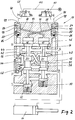
- the working pistons 84 of the two directional valves 80, 82 are acted upon and the two valves are switched to the position shown in FIG. 2, in which the respective ventilation connection 90 is blocked .
- the working piston 86 of the Both directional valves have opened their associated valve seat, so that the cross-channels 94, 96 are connected to the storage chambers 44, 46 via the working connections 88 of the two directional valves 80, 82.
- the working pistons 18 of the valve spindles 16 are thus pressurized by the pressure medium in the storage chambers 44, 46 via the opened directional valves 80, 82 and the cross channels 94, 96 and switch to the switching position shown in FIG.
- the cylinder 14 is thereby switched to the switching position shown in Figure 2.
- a faulty switching is shown in FIG.
- the pilot valve 58 has been switched on, while the pilot valve 60 has remained in its rest position (in the vented position).
- the left directional valve 80 has switched over, so that the right working piston 18 is acted upon by the pressure in the storage chamber 44 via the cross channel 94 and the right valve spindle is brought into the switching position.
- the storage chamber 46 is vented via the bore 48 to the return port R and is therefore depressurized, with the result that no operating pressure is present at the valve piston 86 of the right-hand directional control valve 82.
- the pilot valve 60 is subsequently actuated, the directional control valve 82 is reversed, but since the storage chamber 46 is depressurized, the left-hand working piston 18 is not acted upon and is therefore not reversed. This ensures the safety function.
- the volume of the control lines Since the volume of the control lines has been added to the volume of the storage chambers in the previous safety valves of this type, the volume of the storage chambers relevant for the time function was not always correctly guaranteed.
- the volume of the control lines is eliminated since the storage chambers 44, 46 are connected directly to the piston chambers of the working pistons 18 via the cross channels 94, 96.
- the maximum permissible time difference between the actuation of the pilot valve 58 and the actuation of the pilot valve 60 is only determined by the size of the volume of the storage chambers 44 and 46 and by the size of the nozzles or bores 48.
- the safety valve according to the innovation thus offers the advantage that there is no longer any need to intervene in the safety-relevant interfaces between the main valve and pilot valves.
- the disadvantages of the known valves described at the outset are at least substantially avoided by the direct pressure supply of the main valve from the storage chambers and the integration of the channels 94, 96 into the housing of the safety valve.
- the external pilot valves 58, 60 can therefore be equipped with any control lines 98, 100, furthermore the control pressure can be supplied separately via the line 102 and its height can differ from the main pressure P.
Landscapes
- Engineering & Computer Science (AREA)
- Chemical & Material Sciences (AREA)
- Analytical Chemistry (AREA)
- Physics & Mathematics (AREA)
- Fluid Mechanics (AREA)
- Mechanical Engineering (AREA)
- General Engineering & Computer Science (AREA)
- Fluid-Pressure Circuits (AREA)
- Servomotors (AREA)
- Fluid-Driven Valves (AREA)
Abstract
Description
- Die Neuerung betrifft ein Sicherheitsventil für druckmittelbetätigte Arbeitsglieder, z. B. doppeltwirkende Zylinder von Pressen, mit Zulauf-, Arbeit- und Rücklaufanschlüssen, ferner mit zwei parallel geschalteten, über Vorsteuerventile betätigbaren Ventilspindeln mit Arbeitskolben und Ventilkolben, sowie mit zwei Speicherkammern zur Druckmittelbeaufschlagung der beiden Arbeitskolben.
- Ein Ventil dieser Art ist bekannt aus der DE-OS 36 15 369. Die Vorsteuerventile sind bei diesem bekannten Sicherheitsventil außerhalb des eigentlichen Ventiles angeordnet und mit diesem durch Leitungen verbunden, so daß pro Vorsteuerventil zwei Anschlüsse am Hauptventil erforderlich sind.
Jeweils einer dieser Anschlüsse führt zu einer der Speicherkammern und der andere zum jeweiligen Arbeitskolben der zugeordneten Ventilspindel. - Nachteilig hierbei ist es, daß die Abmessungen der Leitungen von den Vorsteuerventilen zu den Speicherkammern die internen Schaltzeiten des Sicherheitsventiles beeinflussen, da das Volumen der Steuerleitungen zwischen den Vorsteuerventilen und den Speicherkammern das Volumen der letzteren vergrößert. Die Abmessungen dieser Steuerleitungen müssen daher genau vorgegeben und bei der Installation eingehalten werden wodurch die Anwendung des Ventiles eingeschränkt wird. Außerdem kann es geschehen, daß beim Anschließen der von den Vorsteuerventilen kommenden Steuerleitungen an das Sicherheitsventil die Anschlüsse vertauscht werden, wodurch die Sicherheitsfunktion des Ventiles außer Betrieb gesetzt wird.
- Der Neuerung liegt daher die Aufgabe zugrunde, ein Sicherheitsventil der eingangs genannten Art so weiterzubilden, daß die vorgenannten Nachteile jedenfalls im wesentlichen vermieden werden.
Neuerungsgemäß wird dies dadurch erreicht, daß zwischen je einer Speicherkammer und je einem Vorsteuerventil jeweils ein Wegeventil geschaltet ist.
Zweckmäßigerweise sind diese beiden Wegeventile überkreuz an die Arbeitsräume der beiden Arbeitskolben angeschlossen. - Vorzugsweise sind die beiden Wegeventile und die von diesen zu den Arbeitsräumen der Arbeitskolben führenden Kanäle in das Gehäuse des Sicherheitsventils integriert.
- Eine beispielsweise Ausführungsform der Neuerung wird nachfolgend anhand der Zeichnung erläutert, in der
- Figur 1 schematisch im Schnitt ein neuerungsgemäßes Ventil in Ruhestellung zeigt.
- Figur 2 zeigt im Schnitt das Ventil nach Figur 1 in Schaltstellung.
- Figur 3 zeigt das Ventil nach den Figuren 1 und 2 bei einer Fehlschaltung.
- Das Sicherheitsventil 10 nach Figur 1 hat ein Gehäuse 12 und es dient zur Ansteuerung eines doppeltwirkenden Zylinders 14.
Das Gehäuse 12 ist mit einem Zulaufanschluß P, zwei Arbeitsanschlüssen A und B sowie zwei Rücklaufanschlüssen R und S versehen. Im Gehäuse sind zwei parallel geschaltete Ventilspindeln 16 eingebaut, von denen jede einen Arbeitskolben 18, einen Ventilkolben 20 und einen Steuerkolben 32 besitzt. Die Bohrungen, in denen die beiden Ventilspindeln 16 geführt sind, sind überkreuz durch Kanäle 28, 30 miteinander verbunden.
Die beiden Steuerkolben 32 sind in Reihe hintereinander geschaltet und sie liegen in einem Kanal, der vom Arbeitsanschluß B zum Rücklaufanschluß S führt.
Das Sicherheitsventil 10 wird durch Vorsteuerventile 58 und 60 angesteuert, die handbetätigt, aber auch elektrisch, elektromagnetisch, mechanisch oderdruckbetätigt sein können.
Dem Vorsteuerventil 58 ist eine Speicherkammer 44 im Gehäuse 12 und dem Vorsteuerventil 60 ist eine Speicherkammer 46 im Gehäuse 12 zugeordnet wobei die beiden Speicherkammern jeweils über eine Bohrung 48 an die Bohrungen angeschlossen sind, in denen die Ventilspindeln 16 geführt sind. Zwischen diesen vorgenannten Bohrungen und dem Zulauf P ist ein federbelastetes Rückschlagventil 68 eingebaut. Die Speicherkammer 44 ist mit einem Entlüftungsventil 74 versehen, dessen Ventilkolben über eine vom Zulauf P abzweigende Leitung ständig durch den Zulaufdruck beaufschlagt ist. Bei einem Ausfall der Druckversorgung öffnet das Entlüftungsventil 74 und die Speicherkammer 44 wird zur Atmosphäre entlüftet. - Wie die Figuren zeigen, ist zwischen die Speicherkammer 44 und das Vorsteuerventil 58 ein Wegeventil 80 geschaltet, ebenso ist zwischen die Speicherkammer 46 und das Vorsteuerventil 60 ein Wegeventil 82 geschaltet.
Jedes Wegeventil 80, 82 hat einen Arbeitskolben 84, einen Ventilkolben 86, einen Steueranschluß 92, einen Entlüftungsanschluß 90 und einen Arbeitsanschluß 88.
Der Arbeitsanschluß 88 des Wegeventiles 80 ist über einen Kreuzkanal 94 mit dem Arbeitsraum des rechten Arbeitskolbens 18 verbunden und der Arbeitsanschluß 88 des Wegeventiles 82 ist über einen Kreuzkanal 96 mit dem Arbeitsraum des linken Arbeitskolbens 18 verbunden.
Der Steueranschluß 92 des Wegeventiles 80 ist über eine Steuerleitung 98 an das Vorsteuerventil 58 angeschlossen, in gleicher Weise ist der Steueranschluß 92 des Wegeventiles 82 über eine Steuerleitung 100 an das Vorsteuerventil 60 angeschlossen.
Die beiden Vorsteuerventile 58, 60 sind über eine Leitung 102 an eine nicht näher bezeichnete Druckversorgung angeschlossen. - Das neuerungsgemäße Sicherungsventil arbeitet folgendermaßen.
In der Ruhestellung nach Figur 1 sind die beiden Wegeventile 80, 82 über ihre Steuerleitungen 98, 100 und über die beiden Vorsteuerventile 58, 60 entlüftet. Ebenso sind die Arbeitskolben 18 über die Kanäle 94, 96 und die Entlüftungsanschlüsse 90 der beiden Wegeventile 80, 82 entlüftet.
In dieser Stellung ist der Zulaufanschluß P mit dem Arbeitsanschluß B verbunden während der Weg von B zum Rücklaufanschluß S durch die Steuerkolben 32 gesperrt ist. Der Arbeitsanschluß A ist zum Rücklaufanschluß R entlüftet.
Die Ventilkolben 86 der beiden Wegeventile 80, 82 sind durch den Druck in den Speicherkammern 44 und 46 beaufschlagt. - Werden nun die beiden Vorsteuerventile 58, 60 in die in Figur 2 gezeigte Schaltposition umgeschaltet, dann werden die Arbeitskolben 84 der beiden Wegeventile 80, 82 beaufschlagt und die beiden Ventile in die in Figur 2 gezeigte Position umgeschaltet, in der der jeweilige Entlüftungsanschluß 90 gesperrt ist. Die Arbeitskolben 86 der beiden Wegeventile haben ihren zugehörigen Ventilsitz geöffnet, so daß die Kreuzkanäle 94, 96 über die Arbeitsanschlüsse 88 der beiden Wegeventile 80, 82 an die Speicherkammern 44, 46 angeschlossen sind.
Die Arbeitskolben 18 der Ventilspindeln 16 werden somit durch das Druckmittel in den Speicherkammern 44, 46 über die geöffneten Wegeventile 80, 82 und die Kreuzkanäle 94, 96 mit Druck beaufschlagt und schalten in die in Figur 2 gezeigte Schaltstellung um, in der die Verbindung vom Zulaufanschluß P zum Arbeitsanschluß B gesperrt, die Verbindung vom Zulaufanschluß P zum Arbeitsanschluß A dagegen geöffnet ist. Die Verbindung vom Arbeitsanschluß B zum Rücklaufanschluß S ist geöffnet, die Verbindung vom Arbeitsanschluß A zum Rücklaufanschluß R ist durch die Arbeitskolben 18 gesperrt. - Der Zylinder 14 wird dadurch in die in Figur 2 gezeigte Schaltstellung umgeschaltet. In Figur 3 ist eine Fehlschaltung dargestellt. Hier ist nur das Vorsteuerventil 58 eingeschaltet worden, während das Vorsteuerventil 60 in seiner Ruhestellung (in entlüfteter Stellung) geblieben ist.
Das linke Wegeventil 80 hat umgeschaltet, so daß der rechte Arbeitskolben 18 durch den Druck in der Speicherkammer 44 über den Kreuzkanal 94 beaufschlagt wird und die rechte Ventilspindel in Schaltstellung gebracht wird.
Hierdurch wird die Speicherkammer 46 über die Bohrung 48 zum Rücklaufanschluß R entlüftet und damit drucklos, mit der Folge, daß am Ventilkolben 86 des rechten Wegeventiles 82 kein Betriebsdruck ansteht. Wird nun nachträglich das Vorsteuerventil 60 noch betätigt so wird das Wegeventil 82 zwar umgesteuert, da aber die Speicherkammer 46 drucklos ist wird der linke Arbeitskolben 18 nicht beaufschlagt und damit auch nicht umgesteuert.
Die Sicherheitsfunktion ist damit gewährleistet. - Bei Sicherheitsventilen der vorbeschriebenen Art wird davon ausgegangen, daß die beiden Vorsteuerventile innerhalb einer gewissen Zeitspanne betätigt werden müssen, da andernfalls die Sicherheitsfunktion ausgelöst wird. Diese Zeitspanne kann z. B. 0,5 Sekunden betragen.
- Da bei den bisherigen Sicherheitsventilen dieser Art, das Volumen der Steuerleitungen zu dem Volumen der Speicherkammern hinzugekommen ist war das für die Zeitfunktion relevante Volumen der Speicherkammern nicht immer korrekt gewährleistet.
Bei dem neuerungsgemäßen Sicherheitsventil fällt das Volumen der Steuerleitungen weg, da die Speicherkammern 44, 46 über die Kreuzkanäle 94, 96 direkt an die Kolbenräume der Arbeitskolben 18 angeschlossen sind.
Die maximal zulässige Differenzzeit zwischen der Betätigung des Vorsteuerventiles 58 und der Betätigung des Vorsteuerventiles 60 wird nur noch bestimmt durch die Größe des Volumens der Speicherkammern 44 und 46 und durch die Größe der Düsen bzw. Bohrungen 48. - Das neuerungsgemäße Sicherheitsventil bietet somit den Vorteil, daß in die sicherheitsrelevanten Schnittstellen zwischen Hauptventil und Vorsteuerventilen nicht mehr eingegriffen werden muß. Die eingangs beschriebenen Nachteile der bekannten Ventile werden durch die direkte Druckversorgung des Hauptventiles aus den Speicherkammern und die Integration der Kanäle 94, 96 in das Gehäuse des Sicherheitsventiles mindestens im wesentlichen vermieden.
Die externen Vorsteuerventile 58, 60 können daher mit beliebigen Steuerleitungen 98, 100 ausgerüstet werden, ferner kann der Steuerdruck über die Leitung 102 separat zugeführt werden und er kann hinsichtlich seiner Höhe vom Hauptdruck P abweichen.
Claims (3)
- Sicherheitsventil für druckmittelbetätigte Arbeitsglieder, z. B. doppeltwirkende Zylinder von Pressen, mit Zulauf-, Arbeits- und Rücklaufanschlüssen, ferner mit zwei parallel geschalteten, über Vorsteuerventile betätigbaren Ventilspindeln, mit Arbeitskolben und Ventilkolben, sowie mit zwei Speicherkammern zur Druckmittelbeaufschlagung der beiden Arbeitskolben, dadurch gekennzeichnet, daß zwischen je einer Speicherkammer (44, 46) und je einem Vorsteuerventil (58, 60) jeweils ein Wegeventil (80, 82) geschaltet ist.
- Sicherheitsventil nach Anspruch 1, dadurch gekennzeichnet, daß die beiden Wegeventile (80, 82) überkreuz an die Arbeitsräume der beiden Arbeitskolben (18) angeschlossen sind.
- Sicherheitsventil nach Anspruch 1 oder 2, dadurch gekennzeichnet, daß die beiden Wegeventile (80, 82) und die von diesen zu den Arbeitsräumen der Arbeitskolben (18) führenden Kanäle (94, 96) in das Gehäuse (12) des Sicherheitsventiles integriert sind.
Applications Claiming Priority (2)
| Application Number | Priority Date | Filing Date | Title |
|---|---|---|---|
| DE9202938U DE9202938U1 (de) | 1992-03-05 | 1992-03-05 | Sicherheitsventil |
| DE9202938U | 1992-03-05 |
Publications (2)
| Publication Number | Publication Date |
|---|---|
| EP0558976A1 true EP0558976A1 (de) | 1993-09-08 |
| EP0558976B1 EP0558976B1 (de) | 1995-07-26 |
Family
ID=6876898
Family Applications (1)
| Application Number | Title | Priority Date | Filing Date |
|---|---|---|---|
| EP93102268A Expired - Lifetime EP0558976B1 (de) | 1992-03-05 | 1993-02-12 | Sicherheitsventil |
Country Status (3)
| Country | Link |
|---|---|
| EP (1) | EP0558976B1 (de) |
| JP (1) | JP3370721B2 (de) |
| DE (2) | DE9202938U1 (de) |
Cited By (1)
| Publication number | Priority date | Publication date | Assignee | Title |
|---|---|---|---|---|
| EP0684392A1 (de) * | 1994-04-20 | 1995-11-29 | Herion-Werke KG | Sicherheitsventil |
Families Citing this family (10)
| Publication number | Priority date | Publication date | Assignee | Title |
|---|---|---|---|---|
| DE4221756C2 (de) * | 1992-07-02 | 2003-06-12 | Bosch Rexroth Ag | Sicherheitsschaltung für hydraulische Verbraucher |
| SE505573C2 (sv) * | 1995-12-19 | 1997-09-15 | Ross Operating Valve Co | Styranordning med självkontroll av styranordningens komponenter vid varje styrningsoperation |
| SE9602782L (sv) * | 1995-12-19 | 1997-06-16 | Ross Operating Valve Co | Styranordning för tvåhandsreglage vid exempelvis en press |
| SE9600697L (sv) * | 1996-02-23 | 1997-03-24 | Ross Operating Valve Co | Återinkopplingsspärr för ett i varje arbetscykel självkontrollerande styrdon |
| US5799561A (en) * | 1996-07-15 | 1998-09-01 | Ross Operating Valve Company | Control device |
| SE9701523L (sv) * | 1997-04-23 | 1998-06-22 | Rudolf Westerberg Ab | Tvåhandsmanöversystem |
| DE10006141A1 (de) | 2000-02-11 | 2001-09-06 | Zf Lenksysteme Gmbh | Elektrohydraulische Steuervorrichtung |
| DE10034935C2 (de) * | 2000-07-11 | 2002-06-13 | Rexroth Mecman Stockholm Ab | Mehrwegeventil |
| US8794123B2 (en) * | 2010-03-12 | 2014-08-05 | Ross Operating Valve Company | Double valve constructed from unitary single valves |
| DE102012021462B4 (de) | 2012-10-31 | 2018-10-25 | Festo Ag & Co. Kg | Ventileinheit |
Citations (1)
| Publication number | Priority date | Publication date | Assignee | Title |
|---|---|---|---|---|
| DE1245742B (de) * | 1963-03-20 | 1967-07-27 | Concordia Maschinen U Elek Zit | Sicherheitsschaltung zweier vorzugsweise magnetisch betaetigter Vorsteuerventile |
-
1992
- 1992-03-05 DE DE9202938U patent/DE9202938U1/de not_active Expired - Lifetime
-
1993
- 1993-02-12 DE DE59300385T patent/DE59300385D1/de not_active Expired - Fee Related
- 1993-02-12 EP EP93102268A patent/EP0558976B1/de not_active Expired - Lifetime
- 1993-03-02 JP JP06488493A patent/JP3370721B2/ja not_active Expired - Fee Related
Patent Citations (1)
| Publication number | Priority date | Publication date | Assignee | Title |
|---|---|---|---|---|
| DE1245742B (de) * | 1963-03-20 | 1967-07-27 | Concordia Maschinen U Elek Zit | Sicherheitsschaltung zweier vorzugsweise magnetisch betaetigter Vorsteuerventile |
Cited By (1)
| Publication number | Priority date | Publication date | Assignee | Title |
|---|---|---|---|---|
| EP0684392A1 (de) * | 1994-04-20 | 1995-11-29 | Herion-Werke KG | Sicherheitsventil |
Also Published As
| Publication number | Publication date |
|---|---|
| DE59300385D1 (de) | 1995-08-31 |
| JPH0617801A (ja) | 1994-01-25 |
| EP0558976B1 (de) | 1995-07-26 |
| DE9202938U1 (de) | 1992-05-07 |
| JP3370721B2 (ja) | 2003-01-27 |
Similar Documents
| Publication | Publication Date | Title |
|---|---|---|
| DE69704045T2 (de) | Steuerventilverteilerplatte mit innerer oder äusserer Steuerschaltung | |
| EP0558976B1 (de) | Sicherheitsventil | |
| DE68907308T2 (de) | Ventilsystem und Anordnung zum Austauschen von Ventilen während des Betriebes. | |
| DE2232857A1 (de) | Steuergeraet fuer hydraulische arbeitsgeraete | |
| DE3529802A1 (de) | Zweihand-sicherheitssteuerung | |
| DE3615369C2 (de) | Sicherheitsventil | |
| DE2152809A1 (de) | Pneumatischer oder hydraulischer Stellzylinder mit einer Einrichtung zur mechanischen Verriegelung seines Stellkolbens | |
| DE3028396C2 (de) | ||
| DE102021213469B3 (de) | Sicherheitsventileinrichtung | |
| DE4423585C2 (de) | Elektrohydraulische Steuervorrichtung | |
| AT243038B (de) | Vorrichtung zur stufenweisen Erzielung von Arbeitswegen mittels hydraulischer oder pneumatischer Arbeitszylinder | |
| EP0686775A1 (de) | Elektropneumatische Ventileinrichtung | |
| EP0121849A2 (de) | Ventileinrichtung mit einstellbarer Funktion | |
| EP0463394A1 (de) | Elektromagnetisch betätigbares Wegeventil | |
| DE1948038C3 (de) | Elektromagnetisch betätigte Steuereinrichtung | |
| DE3147030C2 (de) | Magnetventileinheit | |
| DE69705919T2 (de) | Hydraulische Betätigungseinrichtung für ein Verdeck eines Kraftfahrzeuges | |
| EP0855520B1 (de) | Ventilanordnung | |
| DE102016212306A1 (de) | Zwischenblock und Kompaktachse mit einem Zwischenblock | |
| DE2852677C3 (de) | Umlaufender, doppeltwirkender Druckmittelzylinder | |
| DE4435339A1 (de) | Anordnung zur Ansteuerung eines hydraulisch betätigbaren Hauptventils | |
| DE2431259A1 (de) | Anhaengerbremssteuerventil | |
| DE2549394C3 (de) | Einrichtung zur Anzeige der Endstellungen des Arbeitskolbens eines doppeltwirkenden druckmittelbetatigten Stellmotors | |
| DE29712709U1 (de) | Mehrwegeventil | |
| DE19523716C2 (de) | Wegeventil mit einem Ventilschieber |
Legal Events
| Date | Code | Title | Description |
|---|---|---|---|
| PUAI | Public reference made under article 153(3) epc to a published international application that has entered the european phase |
Free format text: ORIGINAL CODE: 0009012 |
|
| AK | Designated contracting states |
Kind code of ref document: A1 Designated state(s): DE FR GB IT |
|
| 17P | Request for examination filed |
Effective date: 19931012 |
|
| 17Q | First examination report despatched |
Effective date: 19950105 |
|
| GRAA | (expected) grant |
Free format text: ORIGINAL CODE: 0009210 |
|
| AK | Designated contracting states |
Kind code of ref document: B1 Designated state(s): DE FR GB IT |
|
| REF | Corresponds to: |
Ref document number: 59300385 Country of ref document: DE Date of ref document: 19950831 |
|
| GBT | Gb: translation of ep patent filed (gb section 77(6)(a)/1977) |
Effective date: 19950915 |
|
| ITF | It: translation for a ep patent filed | ||
| ET | Fr: translation filed | ||
| PLBE | No opposition filed within time limit |
Free format text: ORIGINAL CODE: 0009261 |
|
| STAA | Information on the status of an ep patent application or granted ep patent |
Free format text: STATUS: NO OPPOSITION FILED WITHIN TIME LIMIT |
|
| 26N | No opposition filed | ||
| REG | Reference to a national code |
Ref country code: GB Ref legal event code: IF02 |
|
| PGFP | Annual fee paid to national office [announced via postgrant information from national office to epo] |
Ref country code: FR Payment date: 20040112 Year of fee payment: 12 |
|
| PGFP | Annual fee paid to national office [announced via postgrant information from national office to epo] |
Ref country code: GB Payment date: 20040115 Year of fee payment: 12 |
|
| PGFP | Annual fee paid to national office [announced via postgrant information from national office to epo] |
Ref country code: DE Payment date: 20040116 Year of fee payment: 12 |
|
| PG25 | Lapsed in a contracting state [announced via postgrant information from national office to epo] |
Ref country code: IT Free format text: LAPSE BECAUSE OF NON-PAYMENT OF DUE FEES Effective date: 20050212 Ref country code: GB Free format text: LAPSE BECAUSE OF NON-PAYMENT OF DUE FEES Effective date: 20050212 |
|
| PG25 | Lapsed in a contracting state [announced via postgrant information from national office to epo] |
Ref country code: DE Free format text: LAPSE BECAUSE OF NON-PAYMENT OF DUE FEES Effective date: 20050901 |
|
| GBPC | Gb: european patent ceased through non-payment of renewal fee |
Effective date: 20050212 |
|
| PG25 | Lapsed in a contracting state [announced via postgrant information from national office to epo] |
Ref country code: FR Free format text: LAPSE BECAUSE OF NON-PAYMENT OF DUE FEES Effective date: 20051031 |
|
| REG | Reference to a national code |
Ref country code: FR Ref legal event code: ST Effective date: 20051031 |