EP0559251A1 - Verfahren zur Herstellung gegossener, hochtemperaturbeständiger und dünnwandiger Strukturen - Google Patents
Verfahren zur Herstellung gegossener, hochtemperaturbeständiger und dünnwandiger Strukturen Download PDFInfo
- Publication number
- EP0559251A1 EP0559251A1 EP93200297A EP93200297A EP0559251A1 EP 0559251 A1 EP0559251 A1 EP 0559251A1 EP 93200297 A EP93200297 A EP 93200297A EP 93200297 A EP93200297 A EP 93200297A EP 0559251 A1 EP0559251 A1 EP 0559251A1
- Authority
- EP
- European Patent Office
- Prior art keywords
- thin
- core
- alloy
- product
- wall
- Prior art date
- Legal status (The legal status is an assumption and is not a legal conclusion. Google has not performed a legal analysis and makes no representation as to the accuracy of the status listed.)
- Granted
Links
- 238000000034 method Methods 0.000 title claims description 37
- 239000007789 gas Substances 0.000 claims abstract description 16
- 238000004519 manufacturing process Methods 0.000 claims abstract description 3
- 229910045601 alloy Inorganic materials 0.000 claims description 71
- 239000000956 alloy Substances 0.000 claims description 71
- 239000000919 ceramic Substances 0.000 claims description 71
- 238000005266 casting Methods 0.000 claims description 56
- 239000000463 material Substances 0.000 claims description 14
- 239000013078 crystal Substances 0.000 claims description 13
- VYPSYNLAJGMNEJ-UHFFFAOYSA-N silicon dioxide Inorganic materials O=[Si]=O VYPSYNLAJGMNEJ-UHFFFAOYSA-N 0.000 claims description 9
- 238000002347 injection Methods 0.000 claims description 8
- 239000007924 injection Substances 0.000 claims description 8
- 239000010453 quartz Substances 0.000 claims description 7
- 239000000203 mixture Substances 0.000 claims description 5
- 239000011800 void material Substances 0.000 claims description 5
- 229910000601 superalloy Inorganic materials 0.000 claims description 4
- 230000003247 decreasing effect Effects 0.000 claims description 3
- 238000002844 melting Methods 0.000 claims description 3
- 230000008018 melting Effects 0.000 claims description 3
- 238000007711 solidification Methods 0.000 claims description 2
- 230000008023 solidification Effects 0.000 claims description 2
- 229910052751 metal Inorganic materials 0.000 description 12
- 239000002184 metal Substances 0.000 description 12
- 239000004033 plastic Substances 0.000 description 8
- 229920003023 plastic Polymers 0.000 description 8
- PXHVJJICTQNCMI-UHFFFAOYSA-N Nickel Chemical compound [Ni] PXHVJJICTQNCMI-UHFFFAOYSA-N 0.000 description 4
- 239000000843 powder Substances 0.000 description 4
- 230000007547 defect Effects 0.000 description 3
- 238000007598 dipping method Methods 0.000 description 3
- 238000003754 machining Methods 0.000 description 3
- 239000002245 particle Substances 0.000 description 3
- 239000011253 protective coating Substances 0.000 description 3
- 239000002002 slurry Substances 0.000 description 3
- PNEYBMLMFCGWSK-UHFFFAOYSA-N aluminium oxide Inorganic materials [O-2].[O-2].[O-2].[Al+3].[Al+3] PNEYBMLMFCGWSK-UHFFFAOYSA-N 0.000 description 2
- 238000005219 brazing Methods 0.000 description 2
- 239000011248 coating agent Substances 0.000 description 2
- 238000000576 coating method Methods 0.000 description 2
- 238000001816 cooling Methods 0.000 description 2
- 229910052593 corundum Inorganic materials 0.000 description 2
- 238000005553 drilling Methods 0.000 description 2
- 239000000428 dust Substances 0.000 description 2
- 238000000465 moulding Methods 0.000 description 2
- 229910052759 nickel Inorganic materials 0.000 description 2
- 238000005488 sandblasting Methods 0.000 description 2
- 238000003466 welding Methods 0.000 description 2
- 229910001845 yogo sapphire Inorganic materials 0.000 description 2
- VYZAMTAEIAYCRO-UHFFFAOYSA-N Chromium Chemical compound [Cr] VYZAMTAEIAYCRO-UHFFFAOYSA-N 0.000 description 1
- 239000002253 acid Substances 0.000 description 1
- 239000004411 aluminium Substances 0.000 description 1
- 229910052782 aluminium Inorganic materials 0.000 description 1
- XAGFODPZIPBFFR-UHFFFAOYSA-N aluminium Chemical compound [Al] XAGFODPZIPBFFR-UHFFFAOYSA-N 0.000 description 1
- 239000003518 caustics Substances 0.000 description 1
- 229910010293 ceramic material Inorganic materials 0.000 description 1
- 239000011651 chromium Substances 0.000 description 1
- 229910052804 chromium Inorganic materials 0.000 description 1
- 239000008119 colloidal silica Substances 0.000 description 1
- 238000010276 construction Methods 0.000 description 1
- 238000005530 etching Methods 0.000 description 1
- 238000010438 heat treatment Methods 0.000 description 1
- 238000007373 indentation Methods 0.000 description 1
- 230000006698 induction Effects 0.000 description 1
- 238000005495 investment casting Methods 0.000 description 1
- 238000010030 laminating Methods 0.000 description 1
- 238000000059 patterning Methods 0.000 description 1
- 238000009877 rendering Methods 0.000 description 1
- 239000000243 solution Substances 0.000 description 1
- 230000002459 sustained effect Effects 0.000 description 1
- XLYOFNOQVPJJNP-UHFFFAOYSA-N water Substances O XLYOFNOQVPJJNP-UHFFFAOYSA-N 0.000 description 1
Images




Classifications
-
- B—PERFORMING OPERATIONS; TRANSPORTING
- B22—CASTING; POWDER METALLURGY
- B22C—FOUNDRY MOULDING
- B22C21/00—Flasks; Accessories therefor
- B22C21/12—Accessories
- B22C21/14—Accessories for reinforcing or securing moulding materials or cores, e.g. gaggers, chaplets, pins, bars
-
- B—PERFORMING OPERATIONS; TRANSPORTING
- B22—CASTING; POWDER METALLURGY
- B22C—FOUNDRY MOULDING
- B22C19/00—Components or accessories for moulding machines
- B22C19/04—Controlling devices specially designed for moulding machines
-
- B—PERFORMING OPERATIONS; TRANSPORTING
- B22—CASTING; POWDER METALLURGY
- B22C—FOUNDRY MOULDING
- B22C9/00—Moulds or cores; Moulding processes
- B22C9/02—Sand moulds or like moulds for shaped castings
- B22C9/04—Use of lost patterns
-
- B—PERFORMING OPERATIONS; TRANSPORTING
- B22—CASTING; POWDER METALLURGY
- B22C—FOUNDRY MOULDING
- B22C9/00—Moulds or cores; Moulding processes
- B22C9/10—Cores; Manufacture or installation of cores
-
- B—PERFORMING OPERATIONS; TRANSPORTING
- B22—CASTING; POWDER METALLURGY
- B22D—CASTING OF METALS; CASTING OF OTHER SUBSTANCES BY THE SAME PROCESSES OR DEVICES
- B22D19/00—Casting in, on, or around objects which form part of the product
- B22D19/04—Casting in, on, or around objects which form part of the product for joining parts
-
- B—PERFORMING OPERATIONS; TRANSPORTING
- B22—CASTING; POWDER METALLURGY
- B22D—CASTING OF METALS; CASTING OF OTHER SUBSTANCES BY THE SAME PROCESSES OR DEVICES
- B22D19/00—Casting in, on, or around objects which form part of the product
- B22D19/16—Casting in, on, or around objects which form part of the product for making compound objects cast of two or more different metals, e.g. for making rolls for rolling mills
-
- F—MECHANICAL ENGINEERING; LIGHTING; HEATING; WEAPONS; BLASTING
- F01—MACHINES OR ENGINES IN GENERAL; ENGINE PLANTS IN GENERAL; STEAM ENGINES
- F01D—NON-POSITIVE DISPLACEMENT MACHINES OR ENGINES, e.g. STEAM TURBINES
- F01D5/00—Blades; Blade-carrying members; Heating, heat-insulating, cooling or antivibration means on the blades or the members
- F01D5/12—Blades
- F01D5/14—Form or construction
-
- F—MECHANICAL ENGINEERING; LIGHTING; HEATING; WEAPONS; BLASTING
- F01—MACHINES OR ENGINES IN GENERAL; ENGINE PLANTS IN GENERAL; STEAM ENGINES
- F01D—NON-POSITIVE DISPLACEMENT MACHINES OR ENGINES, e.g. STEAM TURBINES
- F01D5/00—Blades; Blade-carrying members; Heating, heat-insulating, cooling or antivibration means on the blades or the members
- F01D5/12—Blades
- F01D5/14—Form or construction
- F01D5/147—Construction, i.e. structural features, e.g. of weight-saving hollow blades
-
- F—MECHANICAL ENGINEERING; LIGHTING; HEATING; WEAPONS; BLASTING
- F01—MACHINES OR ENGINES IN GENERAL; ENGINE PLANTS IN GENERAL; STEAM ENGINES
- F01D—NON-POSITIVE DISPLACEMENT MACHINES OR ENGINES, e.g. STEAM TURBINES
- F01D5/00—Blades; Blade-carrying members; Heating, heat-insulating, cooling or antivibration means on the blades or the members
- F01D5/12—Blades
- F01D5/14—Form or construction
- F01D5/18—Hollow blades, i.e. blades with cooling or heating channels or cavities; Heating, heat-insulating or cooling means on blades
-
- F—MECHANICAL ENGINEERING; LIGHTING; HEATING; WEAPONS; BLASTING
- F01—MACHINES OR ENGINES IN GENERAL; ENGINE PLANTS IN GENERAL; STEAM ENGINES
- F01D—NON-POSITIVE DISPLACEMENT MACHINES OR ENGINES, e.g. STEAM TURBINES
- F01D5/00—Blades; Blade-carrying members; Heating, heat-insulating, cooling or antivibration means on the blades or the members
- F01D5/12—Blades
- F01D5/14—Form or construction
- F01D5/18—Hollow blades, i.e. blades with cooling or heating channels or cavities; Heating, heat-insulating or cooling means on blades
- F01D5/182—Transpiration cooling
-
- F—MECHANICAL ENGINEERING; LIGHTING; HEATING; WEAPONS; BLASTING
- F01—MACHINES OR ENGINES IN GENERAL; ENGINE PLANTS IN GENERAL; STEAM ENGINES
- F01D—NON-POSITIVE DISPLACEMENT MACHINES OR ENGINES, e.g. STEAM TURBINES
- F01D5/00—Blades; Blade-carrying members; Heating, heat-insulating, cooling or antivibration means on the blades or the members
- F01D5/12—Blades
- F01D5/14—Form or construction
- F01D5/18—Hollow blades, i.e. blades with cooling or heating channels or cavities; Heating, heat-insulating or cooling means on blades
- F01D5/182—Transpiration cooling
- F01D5/184—Blade walls being made of perforated sheet laminae
-
- F—MECHANICAL ENGINEERING; LIGHTING; HEATING; WEAPONS; BLASTING
- F01—MACHINES OR ENGINES IN GENERAL; ENGINE PLANTS IN GENERAL; STEAM ENGINES
- F01D—NON-POSITIVE DISPLACEMENT MACHINES OR ENGINES, e.g. STEAM TURBINES
- F01D5/00—Blades; Blade-carrying members; Heating, heat-insulating, cooling or antivibration means on the blades or the members
- F01D5/12—Blades
- F01D5/14—Form or construction
- F01D5/18—Hollow blades, i.e. blades with cooling or heating channels or cavities; Heating, heat-insulating or cooling means on blades
- F01D5/186—Film cooling
-
- F—MECHANICAL ENGINEERING; LIGHTING; HEATING; WEAPONS; BLASTING
- F05—INDEXING SCHEMES RELATING TO ENGINES OR PUMPS IN VARIOUS SUBCLASSES OF CLASSES F01-F04
- F05D—INDEXING SCHEME FOR ASPECTS RELATING TO NON-POSITIVE-DISPLACEMENT MACHINES OR ENGINES, GAS-TURBINES OR JET-PROPULSION PLANTS
- F05D2230/00—Manufacture
- F05D2230/20—Manufacture essentially without removing material
- F05D2230/21—Manufacture essentially without removing material by casting
-
- F—MECHANICAL ENGINEERING; LIGHTING; HEATING; WEAPONS; BLASTING
- F05—INDEXING SCHEMES RELATING TO ENGINES OR PUMPS IN VARIOUS SUBCLASSES OF CLASSES F01-F04
- F05D—INDEXING SCHEME FOR ASPECTS RELATING TO NON-POSITIVE-DISPLACEMENT MACHINES OR ENGINES, GAS-TURBINES OR JET-PROPULSION PLANTS
- F05D2230/00—Manufacture
- F05D2230/30—Manufacture with deposition of material
- F05D2230/31—Layer deposition
-
- F—MECHANICAL ENGINEERING; LIGHTING; HEATING; WEAPONS; BLASTING
- F05—INDEXING SCHEMES RELATING TO ENGINES OR PUMPS IN VARIOUS SUBCLASSES OF CLASSES F01-F04
- F05D—INDEXING SCHEME FOR ASPECTS RELATING TO NON-POSITIVE-DISPLACEMENT MACHINES OR ENGINES, GAS-TURBINES OR JET-PROPULSION PLANTS
- F05D2260/00—Function
- F05D2260/20—Heat transfer, e.g. cooling
- F05D2260/202—Heat transfer, e.g. cooling by film cooling
-
- Y—GENERAL TAGGING OF NEW TECHNOLOGICAL DEVELOPMENTS; GENERAL TAGGING OF CROSS-SECTIONAL TECHNOLOGIES SPANNING OVER SEVERAL SECTIONS OF THE IPC; TECHNICAL SUBJECTS COVERED BY FORMER USPC CROSS-REFERENCE ART COLLECTIONS [XRACs] AND DIGESTS
- Y02—TECHNOLOGIES OR APPLICATIONS FOR MITIGATION OR ADAPTATION AGAINST CLIMATE CHANGE
- Y02T—CLIMATE CHANGE MITIGATION TECHNOLOGIES RELATED TO TRANSPORTATION
- Y02T50/00—Aeronautics or air transport
- Y02T50/60—Efficient propulsion technologies, e.g. for aircraft
-
- Y—GENERAL TAGGING OF NEW TECHNOLOGICAL DEVELOPMENTS; GENERAL TAGGING OF CROSS-SECTIONAL TECHNOLOGIES SPANNING OVER SEVERAL SECTIONS OF THE IPC; TECHNICAL SUBJECTS COVERED BY FORMER USPC CROSS-REFERENCE ART COLLECTIONS [XRACs] AND DIGESTS
- Y10—TECHNICAL SUBJECTS COVERED BY FORMER USPC
- Y10S—TECHNICAL SUBJECTS COVERED BY FORMER USPC CROSS-REFERENCE ART COLLECTIONS [XRACs] AND DIGESTS
- Y10S428/00—Stock material or miscellaneous articles
- Y10S428/922—Static electricity metal bleed-off metallic stock
- Y10S428/923—Physical dimension
-
- Y—GENERAL TAGGING OF NEW TECHNOLOGICAL DEVELOPMENTS; GENERAL TAGGING OF CROSS-SECTIONAL TECHNOLOGIES SPANNING OVER SEVERAL SECTIONS OF THE IPC; TECHNICAL SUBJECTS COVERED BY FORMER USPC CROSS-REFERENCE ART COLLECTIONS [XRACs] AND DIGESTS
- Y10—TECHNICAL SUBJECTS COVERED BY FORMER USPC
- Y10T—TECHNICAL SUBJECTS COVERED BY FORMER US CLASSIFICATION
- Y10T428/00—Stock material or miscellaneous articles
- Y10T428/12—All metal or with adjacent metals
- Y10T428/12292—Workpiece with longitudinal passageway or stopweld material [e.g., for tubular stock, etc.]
-
- Y—GENERAL TAGGING OF NEW TECHNOLOGICAL DEVELOPMENTS; GENERAL TAGGING OF CROSS-SECTIONAL TECHNOLOGIES SPANNING OVER SEVERAL SECTIONS OF THE IPC; TECHNICAL SUBJECTS COVERED BY FORMER USPC CROSS-REFERENCE ART COLLECTIONS [XRACs] AND DIGESTS
- Y10—TECHNICAL SUBJECTS COVERED BY FORMER USPC
- Y10T—TECHNICAL SUBJECTS COVERED BY FORMER US CLASSIFICATION
- Y10T428/00—Stock material or miscellaneous articles
- Y10T428/12—All metal or with adjacent metals
- Y10T428/12361—All metal or with adjacent metals having aperture or cut
-
- Y—GENERAL TAGGING OF NEW TECHNOLOGICAL DEVELOPMENTS; GENERAL TAGGING OF CROSS-SECTIONAL TECHNOLOGIES SPANNING OVER SEVERAL SECTIONS OF THE IPC; TECHNICAL SUBJECTS COVERED BY FORMER USPC CROSS-REFERENCE ART COLLECTIONS [XRACs] AND DIGESTS
- Y10—TECHNICAL SUBJECTS COVERED BY FORMER USPC
- Y10T—TECHNICAL SUBJECTS COVERED BY FORMER US CLASSIFICATION
- Y10T428/00—Stock material or miscellaneous articles
- Y10T428/12—All metal or with adjacent metals
- Y10T428/12389—All metal or with adjacent metals having variation in thickness
-
- Y—GENERAL TAGGING OF NEW TECHNOLOGICAL DEVELOPMENTS; GENERAL TAGGING OF CROSS-SECTIONAL TECHNOLOGIES SPANNING OVER SEVERAL SECTIONS OF THE IPC; TECHNICAL SUBJECTS COVERED BY FORMER USPC CROSS-REFERENCE ART COLLECTIONS [XRACs] AND DIGESTS
- Y10—TECHNICAL SUBJECTS COVERED BY FORMER USPC
- Y10T—TECHNICAL SUBJECTS COVERED BY FORMER US CLASSIFICATION
- Y10T428/00—Stock material or miscellaneous articles
- Y10T428/12—All metal or with adjacent metals
- Y10T428/12493—Composite; i.e., plural, adjacent, spatially distinct metal components [e.g., layers, joint, etc.]
Definitions
- This invention relates to single-cast, high-temperature, thin wall structures and methods of making the same, and more particularly to thin wall hollow structures capable of withstanding impinging gases at high temperatures.
- Thick walled one-piece alloy structures are disclosed in US patent Nos.3,806,276 and 3,192,578.
- Laminated structures having thin walls capable of withstanding high temperature impinging gases have heretofore been known.
- such structures are disclosed in US patent Nos.4,245,769; 4,042,162; 4,004,056; 3,963,368; 3,950,114; 3,933,442; 3,810,711; 3,732,031; 3,726,604; 3,698,834; 3,700,418; 3,644,059; 3,644,060; 3,619,082; 3,616,125; 3,610,769; 3,606,572; 3,606,572; 3,606,573; 3,584,972; 3,527,544; 3,529,905 and 3,497,277.
- the thin walls of such structures are laminated to another thin wall or to a substantially thicker structure by brazing, welding or otherwise bonding.
- the laminating process involves high temperature brazing, welding or bonding materials that directly affect the alloy or otherwise limit the overall high temperature performance of the structure.
- these thin wall layers often have holes formed therein by mechanical means or etching which is time consuming, labour intensive and expensive.
- these laminated thin wall structures are capable of withstanding impinging gases at temperatures higher than the melting point of the alloys which the structures are made from, the process of making the structures is time consuming, labour intensive and extremely expensive.
- Ceramic cores Many prior art methods of casting hollow structures utilize ceramic cores. It has been generally accepted that these ceramic cores must have a density sufficiently low enough such that the core is compressive so that it gives as molten alloy solidifies around the core. It has generally been accepted that if the ceramic core has a density above 60 to 70 percent, the core will be crushed and broken by molten alloy which solidifies around it. It has also generally been accepted that ceramic cores having a thickness less than 0.76 mm (0.03 inches) with such low density less would be crushed and broken during casting. The density of prior art ceramic cores ranges from about 50 to about 60 percent.
- the thin walls are provided by metal which has been cold rolled to a very thin thickness.
- the cold-rolled metal is then etched or machined to provide small holes in the surface thereof.
- the small holes provide a cooling air film over the thin wall as the gas turbine blade is impinged with hot gases.
- This cold-rolled metal must be formed and bonded (or welded sufficiently to provide heat transfer from the thin wall to the main body of the blade) in a curved shape to produce the outer wall of a turbine blade.
- the forming process may result in the distortion of the holes in the wall. If the holes are not properly positioned, or the metal not sufficiently bonded, it is possible to develop hot spots at certain sections on the blade which would be undesirable and would limit production yields. Further, the cold-rolled material must be later heat treated which also could possibly result in varying heat transfer properties across the surface of the blade which also would be undesirable.
- a product in accordance with the present invention is characterised by the features specified in Claim 1.
- the present invention also covers a method of casting, an alloy casting mould, and a core.
- the present invention includes the discovery of a variety of phenomena and agencies which gave rise to an idea of a means for repeatably and reliably producing or casting thin wall hollow structures with dimensional accuracy and having the thickness less than about 0.76 mm (0.03 inches).
- the present invention includes the discovery that the problem of creep of a ceramic shell can be solved by controlling the injection pressure of the molten alloy into a cavity.
- the injection pressure may be controlled as a function of time to cast walls having a thickness less than about 0.76 mm (0.03 inches) without shell creep.
- the present invention includes the discovery that the injection pressure of an alloy into a cavity may be varied as a function of time by using a control orifice to bleed the head pressure off after the thin cavity has been filled.
- the present invention includes the discovery that very thin passageways of about 0.127 mm to 0.381 mm may be formed using a thin core having a density greater than about 70 percent, and preferably about 99 percent or greater.
- the present invention includes the discovery that a thin core having a thickness of about 0.127 mm to 0.381 mm and a density greater than about 70 percent may be used without crushing and breaking when surrounded by solidifying alloy.
- the present invention includes the discovery that such thin cores may be used to form narrow radial passageways, having a width of about 0.127 mm to about 0.381 mm, in casting and such passageways may be formed substantially parallel to a thin outer wall having a thickness of about 0.127 mm to about 0.762 mm.
- the present invention includes the discovery that cores having a thickness of 0.127 mm to 0.381 mm may be used in core making, pattern making and casting process without reducing yields.
- the present invention includes the discovery that a structure may be cast using high density ceramic cores, preferably quartz, having a minimum dimensions of about 0.127 mm to about 13.97 mm to form very small holes in a thin wall structure and to hold the above-described thin core in place during casting.
- These cores can be of any shape.
- the present invention includes the discovery that a pocket may be drilled into a ceramic core so as to receive and hold a narrow diameter rod.
- the present invention includes the discovery that a single-piece, hollow multi-wall structure having a very thin outer wall, an inner wall and a very thin passageway therebetween may be cast using a ceramic core, narrow rod and thin ceramic core construction.
- the present invention includes the discovery that a very thin curved core may be held in position in a casting mould by forming a first ceramic core; coating the first ceramic core with wax or plastic pattern where metal is desired; placing the very thin curved ceramic core on the pattern; drilling a hole through the very thin ceramic core, pattern and into the first ceramic core the form a pocket; inserting a rod through the hole so that the rod is received in the pocket in the first ceramic core; covering the very thin ceramic core with a thin layer of wax or plastic pattern where a thin wall of metal is desired; forming a hole through the thin layer of wax and into the thin ceramic core so as to form an angled pocket in the first core at a predetermined position where force is needed to keep the thin ceramic core in its curved shape; inserting a portion of an outer rod through the hole in the thin layer of wax so as to be received in a pocket from in the main ceramic core or in the thin core so that upon casting the structure a passage is provided through the thin wall and into the cavity formed by the thin core or extending through to the cavity formed
- the invention includes the discovery that defects in the walls of a casting, made using a ceramic shell, may be avoided by sandblasting the above-described thin layer of wax on the face closest to the ceramic shell.
- the present invention includes the discovery of a means for producing single-cast, thin wall structures having smooth outer surfaces and having wall thicknesses as narrow as about 0.127 mm.
- the present invention includes the discovery of a single-cast, thin wall hollow structure capable of withstanding impinging gases at temperatures as high as 2371°C (4300°F) or higher.
- Another advantage of the present invention is that finer details may be made in the thin ceramic core using a laser due to the high density of the core.
- the present invention can be utilized to make structures having multiple thin walls each having a thickness less than about 0.762 mm as illustrated in Figure 8.
- the structures of the present invention have a lighter weight, higher temperature capabilities and greater strength then the laminated thin wall structures of the prior art and are greatly more economical to produce.
- the techniques of the present invention may be used to produce thin walled hollow structures using equiaxed, directionally solidified and single crystal alloy processes.
- a variety of techniques are known for producing equiaxed, directionally solidified and single crystal alloy structures.
- the present invention is particularly suitable for producing very thin walled structures using single crystal casting techniques.
- One such single crystal casting technique is illustrated in Figure 7, which shows a casting mould 100 carried on a water cooled chill plate 102 and received in a mould heater 104.
- a casting furnace 106 includes a vacuum system 108 and an induction melting crucible 110 for pouring molten alloy in the mould 100. Once the molten alloy is poured in the mould, the mould is slowly removed from the furnace by an elevator 112.
- the moulding temperature is preferably heated to at least 1538°C (2800°F) and the single crystal superalloy is heated to 1538°C (2800°F), and the single crystal is grown slowly at about 254 mm/hr (10 inches/hr).
- the mould temperature is heated to about 982°C (1800°F) and the equiaxed alloy temperature is heated to 1538°C (2800°F) and the alloy solidified at 1 mm/min.
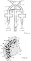
- Figure 1 illustrates a cross-sectional view of a standard mould before injecting molten alloy under pressure.
- the portion of Figure 1 from points A-B represent the alloy charge reservoir, points B-C a charge runner, and points C-D the actual shape of the part to be cast.
- Figure 2 illustrates a cross-sectional view of the distortion of the mould due to sustained pouring or injecting head pressure of the molten alloy.
- Points D-E illustrate the distortion of the casting shell due to "shell creep" under substantial head pressure. The "shell creep" phenomenon precludes the casting of a structure with dimensional accuracy using prior processes.
- the present invention includes the discovery that the problem of "creep" of a ceramic shell can be solved by varying the injection pressure of a molten alloy into a cavity, having a thickness less than about 0.76 mm (0.03 inches), as a function of time. This concept is graphically illustrated in Figure 3. One means of accomplishing this is illustrated in Figure 4.
- Figure 4 illustrates a ceramic shell 10 having a part mould 11 having a cavity 12 for producing a structure with a wall having a thickness less than about 0.76 mm (0.03 inches).
- Molten alloy is injected into the cavity 12 and allowed to solidify to form a desired structure.
- An alloy charge line 14 is located above the area of the mould cavity 12 designated for the desired structure.
- Molten alloy is delivered from a reservoir 16 defined by container 15 through the molten alloy charge line 14 to the structure cavity 12 of the mould 11.
- a charge pressure control means may be a control orifice 18 that is located above the structure cavity 12 of the mould 11 and connected to the alloy charge line 14.
- the charge pressure control means may be a bleed line 20 to remove excess alloy once the cavity 12 has been filled and to reduce the head pressure of the molten alloy thus eliminating the undesirable "creep" of the ceramic shell.
- the bleed line 20 communicates with an excess alloy reservoir 22.
- the excess alloy reservoir 22 is located immediately below the alloy reservoir 16 and is defined by a hollow column 24 which supports container 15.
- a plurality of part moulds 11 may be positioned radially around the column 24 with associated charge lines 14 and bleed lines 20 as described above.
- the typical range of head pressure for casting a wall having a thickness of less than 0.76 mm (0.03 inches) ranges from about 254 mm (10 inches) to about 356 mm (14 inches) of a nickel-based superalloy having a density of about 8.30 Mg/m3 (0.3 lbs./in.3).
- the technique may be used to fill cavities less than 0.76 mm (0.03 inches) thick, and up to 1.52 m (5 feet) high and 0.61 m (2 feet) wide.
- the present invention includes the discovery that very thin passageways of about 0.127 to about 0.381 mm (0.005 to about 0.015 inches) wide, can be formed using a thin core having a density greater than about 70 percent, and preferably about or greater than 99 percent.
- the present invention uses thin cores having a thickness less than about 0.127 to about 0.508 mm (0.005 to about 0.020 inches) and having a density greater than about 99 percent. These cores may be made out of a ceramic material or a plastics material. It has been discovered that the high density of such thin cores gives the thin core sufficient strength to withstand core, wax pattern, mould and casting processes.
- a suitable material for use in such thin cores is a silica (SiO2) material, commonly called quartz.
- the surface of the core may be patterned to provide pedestals or indentations by machining or preferably by laser patterning.
- the very thin ceramic core having a thickness less than about 0.76 mm (0.03 inches) may be shaped before or after making holes in it by, for example, a process of "creep" forming over a contoured die.
- the very thin ceramic core can be made from a variety of materials capable of withstanding the alloy casting temperatures and which can be easily removed with a strong acid or base or can be burned out ash free.
- a preferred material for the very thin ceramic core is quartz.
- Figure 6 illustrates a suitable thin ceramic core having a pattern formed by a laser on the surface thereof. The pattern forms channels and pedestals in the cast part to increase surface area for heat exchange.
- the present invention includes the discovery that a thin wall structure can be cast using rods having a diameter of about 2.29 to about 14.0 mm (0.09 to about 0.55 inches) to form very small holes in a thin wall structure and to hold the above-described thin core in place during casting.
- the holes may be formed by a variety of shaped structures in addition to rods depending on the desired objectives.
- holes in the thin wall may be formed with precision using rods which are placed in a predetermined position so that when the wall structure is cast, the holes would be perfectly positioned on the surface of the thin wall.
- the use of such rods are particularly advantageous when a curved surface having holes therein is desired. Machining holes on a curved surface of a thin wall is very difficult, time consuming and expensive.
- rods are used to cast the structure with very narrow holes thus eliminating machining.
- the rods in order to do so the rods must be received in a pocket formed in the core.
- the pocket may be formed in the core during the core moulding process or may be subsequently formed in the moulded core by a variety of means such as drilling or directing a laser beam on the core.
- the present invention includes the discovery that in one embodiment a pocket 26 ( Figure 5) can be drilled into a ceramic core 28 so as to receive and hold the above-described narrow diameter rod 30 in the ceramic core if the core to be drilled is free of the normal protective coating used in the art.
- the present invention includes a process which avoids using a protective coating on the ceramic core. As illustrated in Figure 5, the ceramic core 28 free of protective coating is drilled to provide the pocket 26 for receiving and holding the narrow diameter rod 30 in the ceramic core to provide passageways from the void formed by the main core 28 to the thin void formed by the thin ceramic core 32 and to hold the thin ceramic core 32 in fixed relationship between a casting shell 44 and the main core 28.
- the pocket 26 is made sufficiently large enough to receive the rod 30 yet small enough to firmly hold it in place and withstand any thermal expansion of the rod or ceramic core during the casting process. Generally a clearance ranging from about 0.0127 to about 0.0254 mm (0.0005 to about 0.001 inches) greater than the diameter of the rod 30 is sufficient.
- the rod 30 may be made out of quartz, Al203 or other similar material.
- the present invention includes a method for holding the very thin, curved core 32 in position in the casting process.
- a first ceramic core 28 is prepared and coated with a first pattern 34 of wax or plastics where metal is desired.
- a curved, very thin core 32 is placed on the first pattern 34 and initially located with locating pins (not shown).
- the locating pins are positioned near the corners of the thin core 32 and extend into the pattern 34 so as to temporarily hold the thin core in position while the subsequently described hole making process takes place.
- a hole is drilled through the very thin ceramic core 32, pattern 34 and into the first ceramic core 28 to form a pocket 26 in the first core 28 for receiving and holding in place a small diameter rod 30.
- a small diameter rod 30 is inserted through the hole so that the rod is received in the pocket 26 formed in the first ceramic core 28.
- the very thin ceramic core 32 is then covered with a thin pattern 36 of wax or plastics (or other suitable material) where a thin wall of metal is desired. Then holes are formed at an angle through the thin pattern 36 and into the thin ceramic core 32 to form a pocket 38 at a predetermined position where force is needed to keep the thin ceramic core in its curved shape.
- the thin ceramic core 32 may be already curved, the core has a resiliency or elasticity that cause it to want to move out of a curved shape such as that needed to make a gas-turbine blade.
- a portion of an outer rod 40 is inserted through the hole in the thin pattern 36 so as to be received in the pocket 38 of the thin ceramic core 32. Finally, the thin pattern 36 and the other portion of the outer rod 40 are covered with a ceramic shell 44.
- the thin core 32 may also be held in position by a geometric relationship of the core and holding rods.
- a rod may extend through a thin curved core so that the longitudinal axis of the rod is at an angle of ninety degrees or greater to a line tangential to the curved core surface at a point near the longitudinal axis of the rod. This arrangement prevents the core from moving.
- a substantially straight air passageway may be formed by placing a rod 46 which extend through the thin pattern 36, thin core 32, first pattern 34 and is carried on one end by the casting shell 44 and by the main core 28 on the other end.
- a labyrinth for air flow may be formed by a first rod 48 held on one end by the casting shell 44 and extend through the thin pattern 36 and the thin core 32.
- a second rod 50 is positioned a distance laterally from the first rod 48, is held on one end by the main core 28 and extends through the first pattern 34 and the thin core 32.
- the entire mould is preheated to cause the wax to flow out of the mould leaving a cavity for molten alloy and so that the cores are held firmly in place.
- the alloy is then cast in the mould as described above and the pins and cores are removed, for example, with a caustic solution.
- the present invention includes the discovery that defects in the wall of a casting made using a ceramic shell can be avoided by reducing the surface tension of the above-described thin layer of wax or plastics on the face closest to the ceramic shell.
- One way to reduce the surface tension of the wax or plastics pattern is to sandblast the pattern's outer surface.
- the thin layer of wax and other portions of the outer rod are covered with a ceramic shell.
- the ceramic shell covering is made by first dipping the thin layer of wax in a slurry having ceramic particles in a colloidal silica vehicle.
- a suitable ceramic powder may have a mesh size of about 325.
- the mould is then dipped into dry ceramic refractory powder to give strength to the shell.
- the process of dipping the mould into a ceramic slurry followed by dry ceramic refractory powder is repeated until a sufficient thickness of the shell is achieved, for example, a thickness of about 12.7 mm (1/2 inch).
- the ceramic slurry and dry powder are dried in an oven at a temperature of about 22-26°C (72-78°F), at 10 percent to 30 percent relative humidity during each dipping step.
- the shell may produce dust particles having a size ranging from about 0.0254 to about 0.0762 mm (1/1000 to about 3/1000 inch). It has been discovered that when the mould is heated the wax expands upon heating to accumulate ceramic dust particles which individually have a size ranging from about 0.0254 to about 0.0762 mm (1/1000 to about 3/1000 inch in sufficient amounts so as to produce in the cast structure surfaces defects having a size of 0.508 mm (20/1000 inch) or greater. It has also been discovered that this problem can be eliminated by altering the surface tension of the wax or plastics prior to coating with the ceramic shell.
- Particularly suitable sandblasting material is 120 grit Al2O3 used at a pressure ranging from about 34.5 to about 68.9 kPa (5 to about 10 psi).
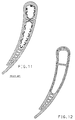
- Figure 8 illustrates a single piece, thin walled, gas-turbine blade according to the present invention with portions removed.
- Figure 9 is a sectional view of a single piece, multi-wall structure according to the present invention.
- This single-cast, thin wall structure is capable of withstanding impinging gases at temperatures as high as 2371°C (4300°F).
- gas turbine blades such as jet engine nozzles 400 (illustrated in Figure 9), leading edge 404 of wings and similar structures for above atmosphere air/space craft 402 (illustrated in Figure 10).
- a variety of thin walled hollow structure may be cast having equiaxed, single crystal and directional solidified structures.
- the very thin wall may have a thickness ranging from about 0.254 to about 1.016 mm (10/1000 to about 40/1000 inches) and preferably about 0.254 to abouut 0.381 mm (10/1000 to about 15/1000 inches).
- the very thin wall may have a thickness of about 0.0762 to about 1.016 mm (3/1000 to about 40/1000 inches), preferably 0.0762 - 0.508 mm (3/1000-20/1000 inches), and most preferably about 0.0762 to about 0.254 mm (3/1000 to about 10/1000 inches).
- Thin walled hollow structure having such thickness can be cast with dimensional accuracy using the processes of the present invention.
- the expression "having a thickness ranging from about 0.0762 to about 1.016 mm (3/1000 to about 40/1000 inches)" is intended to convey the invention as including a thickness ranging from about 0.0762-0.127 mm (3/1000-5/1000 inches), and from about 0.127-0.381 mm (5/1000-15/1000 inches).
Landscapes
- Engineering & Computer Science (AREA)
- Mechanical Engineering (AREA)
- General Engineering & Computer Science (AREA)
- Architecture (AREA)
- Molds, Cores, And Manufacturing Methods Thereof (AREA)
- Turbine Rotor Nozzle Sealing (AREA)
- Crystals, And After-Treatments Of Crystals (AREA)
- Compounds Of Alkaline-Earth Elements, Aluminum Or Rare-Earth Metals (AREA)
- Moulds For Moulding Plastics Or The Like (AREA)
- Compositions Of Oxide Ceramics (AREA)
Priority Applications (3)
| Application Number | Priority Date | Filing Date | Title |
|---|---|---|---|
| EP96107926A EP0750956B1 (de) | 1992-02-18 | 1993-02-04 | Verfahren zur Herstellung gegossener, hochtemperaturbeständiger und dünnwandiger Strukturen |
| EP00117558A EP1053803A3 (de) | 1992-02-18 | 1993-02-04 | Kern zum Giessen von Legierungsstrukturen |
| EP96107927A EP0752291B1 (de) | 1992-02-18 | 1993-02-04 | Kern für das Giessen hochtemperaturbeständiger und dünnwandiger Strukturen |
Applications Claiming Priority (2)
| Application Number | Priority Date | Filing Date | Title |
|---|---|---|---|
| US07/838,154 US5295530A (en) | 1992-02-18 | 1992-02-18 | Single-cast, high-temperature, thin wall structures and methods of making the same |
| US838154 | 1992-02-18 |
Related Child Applications (2)
| Application Number | Title | Priority Date | Filing Date |
|---|---|---|---|
| EP96107926A Division EP0750956B1 (de) | 1992-02-18 | 1993-02-04 | Verfahren zur Herstellung gegossener, hochtemperaturbeständiger und dünnwandiger Strukturen |
| EP96107927A Division EP0752291B1 (de) | 1992-02-18 | 1993-02-04 | Kern für das Giessen hochtemperaturbeständiger und dünnwandiger Strukturen |
Publications (2)
| Publication Number | Publication Date |
|---|---|
| EP0559251A1 true EP0559251A1 (de) | 1993-09-08 |
| EP0559251B1 EP0559251B1 (de) | 1998-12-02 |
Family
ID=25276404
Family Applications (4)
| Application Number | Title | Priority Date | Filing Date |
|---|---|---|---|
| EP00117558A Withdrawn EP1053803A3 (de) | 1992-02-18 | 1993-02-04 | Kern zum Giessen von Legierungsstrukturen |
| EP96107926A Expired - Lifetime EP0750956B1 (de) | 1992-02-18 | 1993-02-04 | Verfahren zur Herstellung gegossener, hochtemperaturbeständiger und dünnwandiger Strukturen |
| EP96107927A Expired - Lifetime EP0752291B1 (de) | 1992-02-18 | 1993-02-04 | Kern für das Giessen hochtemperaturbeständiger und dünnwandiger Strukturen |
| EP93200297A Expired - Lifetime EP0559251B1 (de) | 1992-02-18 | 1993-02-04 | Verfahren und Form zur Herstellung gegossener, hochtemperaturbeständiger und dünnwandiger Strukturen und das hergestellte Produkt |
Family Applications Before (3)
| Application Number | Title | Priority Date | Filing Date |
|---|---|---|---|
| EP00117558A Withdrawn EP1053803A3 (de) | 1992-02-18 | 1993-02-04 | Kern zum Giessen von Legierungsstrukturen |
| EP96107926A Expired - Lifetime EP0750956B1 (de) | 1992-02-18 | 1993-02-04 | Verfahren zur Herstellung gegossener, hochtemperaturbeständiger und dünnwandiger Strukturen |
| EP96107927A Expired - Lifetime EP0752291B1 (de) | 1992-02-18 | 1993-02-04 | Kern für das Giessen hochtemperaturbeständiger und dünnwandiger Strukturen |
Country Status (5)
| Country | Link |
|---|---|
| US (5) | US5295530A (de) |
| EP (4) | EP1053803A3 (de) |
| JP (2) | JPH0655256A (de) |
| CA (1) | CA2077222C (de) |
| DE (3) | DE69330212T2 (de) |
Cited By (27)
| Publication number | Priority date | Publication date | Assignee | Title |
|---|---|---|---|---|
| EP0694677A1 (de) * | 1994-07-29 | 1996-01-31 | United Technologies Corporation | Schaufelspitzendichtungsring für eine Gasturbine |
| EP0750957A1 (de) * | 1995-06-07 | 1997-01-02 | Allison Engine Company, Inc. | Einstückig gegossene, hochtemperaturbeständige, dünnwandige Strukturen, deren Wände mit einem eingegossenen Verbindungselement höherer Wärmeleitfähigkeit verbunden sind |
| WO1998045577A1 (de) * | 1997-04-07 | 1998-10-15 | Siemens Aktiengesellschaft | Verfahren zur kühlung einer turbinenschaufel |
| EP0877657A4 (de) * | 1995-07-11 | 1998-11-18 | ||
| EP1674174A1 (de) * | 2004-12-27 | 2006-06-28 | Siemens Aktiengesellschaft | Verfahren zur Herstellung einer Gussform |
| EP1769862A1 (de) * | 2005-10-03 | 2007-04-04 | United Technologies Corporation | Verfahren zur Herstellung von Kerne und verlorene Modelle Anordnung für gegossene Hohlkörper |
| US7237595B2 (en) | 2003-10-29 | 2007-07-03 | Siemens Aktiengesellschaft | Casting mold |
| EP1815923A1 (de) * | 2006-01-30 | 2007-08-08 | United Technologies Corporation | Metallisch beschichtete Kerne zum Gießen dünner Wände |
| EP1876325A3 (de) * | 2006-07-05 | 2013-06-12 | United Technologies Corporation | Externes Festlegungssystem und Positionierung von Filmkühlbohrungen mittels Kernfestlegungslöchern |
| WO2016174694A1 (en) * | 2015-04-30 | 2016-11-03 | Europea Microfusioni Aerospaziali S.P.A. | Furnace for the production of components made of superalloy by means of the process of investment casting |
| EP3108984A1 (de) * | 2015-06-23 | 2016-12-28 | Rolls-Royce Corporation | Automatisiertes bi-casting |
| US9579714B1 (en) | 2015-12-17 | 2017-02-28 | General Electric Company | Method and assembly for forming components having internal passages using a lattice structure |
| EP2589447A3 (de) * | 2011-11-07 | 2017-06-28 | United Technologies Corporation | Metallgießvorrichtung, Gusswerkstück und Verfahren dafür |
| ITUA20164081A1 (it) * | 2016-06-03 | 2017-12-03 | Europea Microfusioni Aerospaziali S P A | Sonda di temperatura per la misurazione automatizzata della temperatura di un forno di fusione e relativo procedimento di misurazione. |
| US9968991B2 (en) | 2015-12-17 | 2018-05-15 | General Electric Company | Method and assembly for forming components having internal passages using a lattice structure |
| US9987677B2 (en) | 2015-12-17 | 2018-06-05 | General Electric Company | Method and assembly for forming components having internal passages using a jacketed core |
| US10046389B2 (en) | 2015-12-17 | 2018-08-14 | General Electric Company | Method and assembly for forming components having internal passages using a jacketed core |
| US10099284B2 (en) | 2015-12-17 | 2018-10-16 | General Electric Company | Method and assembly for forming components having a catalyzed internal passage defined therein |
| US10099283B2 (en) | 2015-12-17 | 2018-10-16 | General Electric Company | Method and assembly for forming components having an internal passage defined therein |
| US10099276B2 (en) | 2015-12-17 | 2018-10-16 | General Electric Company | Method and assembly for forming components having an internal passage defined therein |
| US10118217B2 (en) | 2015-12-17 | 2018-11-06 | General Electric Company | Method and assembly for forming components having internal passages using a jacketed core |
| US10137499B2 (en) | 2015-12-17 | 2018-11-27 | General Electric Company | Method and assembly for forming components having an internal passage defined therein |
| US10150158B2 (en) | 2015-12-17 | 2018-12-11 | General Electric Company | Method and assembly for forming components having internal passages using a jacketed core |
| US10286450B2 (en) | 2016-04-27 | 2019-05-14 | General Electric Company | Method and assembly for forming components using a jacketed core |
| US10335853B2 (en) | 2016-04-27 | 2019-07-02 | General Electric Company | Method and assembly for forming components using a jacketed core |
| CN112620583A (zh) * | 2020-12-23 | 2021-04-09 | 重庆江增机械有限公司 | 一种球铁铸件薄壁上狭长孔槽的制作方法 |
| WO2025165245A1 (en) * | 2024-01-30 | 2025-08-07 | Ge Infrastructure Technology Llc | Systems and methods for limiting core movement during firing of ceramic molds |
Families Citing this family (131)
| Publication number | Priority date | Publication date | Assignee | Title |
|---|---|---|---|---|
| JPS60104419A (ja) * | 1983-11-12 | 1985-06-08 | Aisin Seiki Co Ltd | 開口覆材の自動開閉装置 |
| US5295530A (en) * | 1992-02-18 | 1994-03-22 | General Motors Corporation | Single-cast, high-temperature, thin wall structures and methods of making the same |
| US5465780A (en) * | 1993-11-23 | 1995-11-14 | Alliedsignal Inc. | Laser machining of ceramic cores |
| US5662160A (en) * | 1995-10-12 | 1997-09-02 | General Electric Co. | Turbine nozzle and related casting method for optimal fillet wall thickness control |
| US5623985A (en) * | 1996-03-13 | 1997-04-29 | Pcc Airfoils, Inc. | Apparatus and method for molding an article |
| US5853044A (en) * | 1996-04-24 | 1998-12-29 | Pcc Airfoils, Inc. | Method of casting an article |
| US5950705A (en) * | 1996-12-03 | 1999-09-14 | General Electric Company | Method for casting and controlling wall thickness |
| EP0894558A1 (de) * | 1997-07-29 | 1999-02-03 | Siemens Aktiengesellschaft | Turbinenschaufel sowie Verfahren zur Herstellung einer Turbinenschaufel |
| RU2126308C1 (ru) * | 1998-01-23 | 1999-02-20 | Государственное предприятие Всероссийский научно-исследовательский институт авиационных материалов | Способ изготовления составного керамического стержня для литья полых изделий |
| DE19819166A1 (de) * | 1998-04-24 | 1999-11-04 | Siemens Ag | Verfahren zur Erfassung eines thermischen Abbildes eines Verbrauchers |
| US6190133B1 (en) | 1998-08-14 | 2001-02-20 | Allison Engine Company | High stiffness airoil and method of manufacture |
| US6050325A (en) * | 1998-09-16 | 2000-04-18 | Pcc Airfoils, Inc. | Method of casting a thin wall |
| US6932145B2 (en) | 1998-11-20 | 2005-08-23 | Rolls-Royce Corporation | Method and apparatus for production of a cast component |
| US7343960B1 (en) * | 1998-11-20 | 2008-03-18 | Rolls-Royce Corporation | Method and apparatus for production of a cast component |
| EP2359958B1 (de) | 1998-11-20 | 2017-06-07 | Rolls-Royce Corporation | Herstellungsverfahren von keramischer Gussformsystem |
| US6186217B1 (en) | 1998-12-01 | 2001-02-13 | Howmet Research Corporation | Multipiece core assembly |
| US6347660B1 (en) * | 1998-12-01 | 2002-02-19 | Howmet Research Corporation | Multipiece core assembly for cast airfoil |
| JP3835973B2 (ja) * | 1999-06-18 | 2006-10-18 | 日本碍子株式会社 | 薄肉部付き鋳造物の製造方法 |
| US6626230B1 (en) | 1999-10-26 | 2003-09-30 | Howmet Research Corporation | Multi-wall core and process |
| US6786982B2 (en) | 2000-01-10 | 2004-09-07 | General Electric Company | Casting having an enhanced heat transfer, surface, and mold and pattern for forming same |
| US6302185B1 (en) * | 2000-01-10 | 2001-10-16 | General Electric Company | Casting having an enhanced heat transfer surface, and mold and pattern for forming same |
| US6502622B2 (en) * | 2001-05-24 | 2003-01-07 | General Electric Company | Casting having an enhanced heat transfer, surface, and mold and pattern for forming same |
| US6557621B1 (en) * | 2000-01-10 | 2003-05-06 | Allison Advanced Development Comapny | Casting core and method of casting a gas turbine engine component |
| US6443700B1 (en) | 2000-11-08 | 2002-09-03 | General Electric Co. | Transpiration-cooled structure and method for its preparation |
| US6505678B2 (en) | 2001-04-17 | 2003-01-14 | Howmet Research Corporation | Ceramic core with locators and method |
| US6403020B1 (en) | 2001-08-07 | 2002-06-11 | Howmet Research Corporation | Method for firing ceramic cores |
| JP3831638B2 (ja) * | 2001-08-09 | 2006-10-11 | 三菱重工業株式会社 | 板状体接合方法、接合体、ガスタービン燃焼器用の尾筒、及び、ガスタービン燃焼器 |
| US6637500B2 (en) * | 2001-10-24 | 2003-10-28 | United Technologies Corporation | Cores for use in precision investment casting |
| US6974308B2 (en) | 2001-11-14 | 2005-12-13 | Honeywell International, Inc. | High effectiveness cooled turbine vane or blade |
| US6551063B1 (en) | 2001-12-20 | 2003-04-22 | General Electric Company | Foil formed structure for turbine airfoil trailing edge |
| US6837687B2 (en) | 2001-12-20 | 2005-01-04 | General Electric Company | Foil formed structure for turbine airfoil |
| US6640546B2 (en) | 2001-12-20 | 2003-11-04 | General Electric Company | Foil formed cooling area enhancement |
| FR2836282B1 (fr) * | 2002-02-19 | 2004-04-02 | Commissariat Energie Atomique | Structure alveolaire et procede de fabrication d'une telle structure |
| US6676381B2 (en) * | 2002-04-03 | 2004-01-13 | General Electric Company | Method and apparatus for casting near-net shape articles |
| US6615899B1 (en) | 2002-07-12 | 2003-09-09 | Honeywell International Inc. | Method of casting a metal article having a thinwall |
| US20050006047A1 (en) * | 2003-07-10 | 2005-01-13 | General Electric Company | Investment casting method and cores and dies used therein |
| US7201212B2 (en) * | 2003-08-28 | 2007-04-10 | United Technologies Corporation | Investment casting |
| RU2252109C1 (ru) * | 2003-09-16 | 2005-05-20 | Федеральное государственное унитарное предприятие "Всероссийский научно-исследовательский институт авиационных материалов" (ФГУП "ВИАМ") | Способ литья полых охлаждаемых изделий и литое полое охлаждаемое изделие |
| DE10346366A1 (de) * | 2003-09-29 | 2005-04-28 | Rolls Royce Deutschland | Turbinenschaufel für ein Flugzeugtriebwerk und Gießform zu deren Herstellung |
| US20050087319A1 (en) * | 2003-10-16 | 2005-04-28 | Beals James T. | Refractory metal core wall thickness control |
| GB0327462D0 (en) * | 2003-11-26 | 2003-12-31 | Rolls Royce Plc | An arrangement for providing heat to a portion of a component of a gas turbine engine |
| US7036556B2 (en) * | 2004-02-27 | 2006-05-02 | Oroflex Pin Development Llc | Investment casting pins |
| US7302990B2 (en) * | 2004-05-06 | 2007-12-04 | General Electric Company | Method of forming concavities in the surface of a metal component, and related processes and articles |
| US7464554B2 (en) * | 2004-09-09 | 2008-12-16 | United Technologies Corporation | Gas turbine combustor heat shield panel or exhaust panel including a cooling device |
| FR2875425B1 (fr) * | 2004-09-21 | 2007-03-30 | Snecma Moteurs Sa | Procede de fabrication d'une aube de turbomachine, assemblage de noyaux pour la mise en oeuvre du procede. |
| US7448433B2 (en) * | 2004-09-24 | 2008-11-11 | Honeywell International Inc. | Rapid prototype casting |
| US7093645B2 (en) * | 2004-12-20 | 2006-08-22 | Howmet Research Corporation | Ceramic casting core and method |
| RU2283722C1 (ru) * | 2005-03-25 | 2006-09-20 | Федеральное государственное унитарное предприятие "Московское машиностроительное производственное предприятие "САЛЮТ" (ФГУП "ММПП "САЛЮТ") | Способ получения литейных керамических стержней |
| US20060231535A1 (en) | 2005-04-19 | 2006-10-19 | Fuesting Timothy P | Method of welding a gamma-prime precipitate strengthened material |
| US7325587B2 (en) * | 2005-08-30 | 2008-02-05 | United Technologies Corporation | Method for casting cooling holes |
| US8575513B2 (en) * | 2006-07-06 | 2013-11-05 | Siemens Energy, Inc. | Rapid prototyping of ceramic articles |
| US7699583B2 (en) * | 2006-07-21 | 2010-04-20 | United Technologies Corporation | Serpentine microcircuit vortex turbulatons for blade cooling |
| EP1882818B1 (de) * | 2006-07-18 | 2013-06-05 | United Technologies Corporation | Wirbelerzeuger in serpentinenartigen Mikrokanälen zur Schaufelkühlung |
| US20080110024A1 (en) * | 2006-11-14 | 2008-05-15 | Reilly P Brennan | Airfoil casting methods |
| US7624787B2 (en) * | 2006-12-06 | 2009-12-01 | General Electric Company | Disposable insert, and use thereof in a method for manufacturing an airfoil |
| US7938168B2 (en) * | 2006-12-06 | 2011-05-10 | General Electric Company | Ceramic cores, methods of manufacture thereof and articles manufactured from the same |
| DE102007012321A1 (de) * | 2007-03-09 | 2008-09-11 | Rolls-Royce Deutschland Ltd & Co Kg | Verfahren zum Feingießen von metallischen Bauteilen mit dünnen Durchgangskanälen |
| US20100025001A1 (en) * | 2007-06-25 | 2010-02-04 | Ching-Pang Lee | Methods for fabricating gas turbine components using an integrated disposable core and shell die |
| FR2927269B1 (fr) * | 2008-02-13 | 2010-10-29 | C T I F Ct Tech Des Ind De La | Preforme et procede pour la fabrication d'une piece dont une partie interieure est en mousse metallique |
| US7918265B2 (en) * | 2008-02-14 | 2011-04-05 | United Technologies Corporation | Method and apparatus for as-cast seal on turbine blades |
| EP2199725B1 (de) * | 2008-12-16 | 2011-10-12 | Siemens Aktiengesellschaft | Multi-Impingement-Verbund zum Kühlen einer Wand |
| US20100272953A1 (en) * | 2009-04-28 | 2010-10-28 | Honeywell International Inc. | Cooled hybrid structure for gas turbine engine and method for the fabrication thereof |
| ES2704138T3 (es) * | 2009-05-20 | 2019-03-14 | Howmet Corp | Recubrimiento de Pt-Al-Hf/Zr y método |
| US20110094698A1 (en) | 2009-10-28 | 2011-04-28 | Howmet Corporation | Fugitive core tooling and method |
| US10337404B2 (en) * | 2010-03-08 | 2019-07-02 | General Electric Company | Preferential cooling of gas turbine nozzles |
| US8936068B2 (en) * | 2010-06-01 | 2015-01-20 | Siemens Energy, Inc. | Method of casting a component having interior passageways |
| GB201016335D0 (en) * | 2010-09-29 | 2010-11-10 | Rolls Royce Plc | Endwall component for a turbine stage of a gas turbine engine |
| US8899303B2 (en) | 2011-05-10 | 2014-12-02 | Howmet Corporation | Ceramic core with composite insert for casting airfoils |
| US8915289B2 (en) * | 2011-05-10 | 2014-12-23 | Howmet Corporation | Ceramic core with composite insert for casting airfoils |
| US9260191B2 (en) * | 2011-08-26 | 2016-02-16 | Hs Marston Aerospace Ltd. | Heat exhanger apparatus including heat transfer surfaces |
| US8956700B2 (en) | 2011-10-19 | 2015-02-17 | General Electric Company | Method for adhering a coating to a substrate structure |
| US20130104567A1 (en) * | 2011-10-31 | 2013-05-02 | Douglas Gerard Konitzer | Method and apparatus for cooling gas turbine rotor blades |
| US9649686B2 (en) * | 2012-02-22 | 2017-05-16 | General Electric Company | Casting preforms and methods of use thereof |
| EP2735387A1 (de) * | 2012-11-22 | 2014-05-28 | Siemens Aktiengesellschaft | Gussform mit angeschrägten Stirnseiten bei inneren Wänden |
| US10018052B2 (en) | 2012-12-28 | 2018-07-10 | United Technologies Corporation | Gas turbine engine component having engineered vascular structure |
| WO2014105108A1 (en) | 2012-12-28 | 2014-07-03 | United Technologies Corporation | Gas turbine engine component having vascular engineered lattice structure |
| US10173932B1 (en) | 2012-12-31 | 2019-01-08 | General Electric Company | Disposable core die and method of fabricating a ceramic body |
| US9835035B2 (en) | 2013-03-12 | 2017-12-05 | Howmet Corporation | Cast-in cooling features especially for turbine airfoils |
| JP6537221B2 (ja) | 2013-03-13 | 2019-07-03 | ハウメット コーポレイションHowmet Corporation | 複合インサートを有するエアフォイル鋳造用セラミックコア |
| DE102013016868A1 (de) * | 2013-10-11 | 2015-04-16 | Flc Flowcastings Gmbh | Feingussverfahren hohler Bauteile |
| CN104646633B (zh) * | 2013-11-20 | 2017-06-30 | 沈阳工业大学 | 局部可自由伸缩的单晶叶片用复杂结构陶瓷型芯制备工艺 |
| GB201411332D0 (en) | 2014-06-26 | 2014-08-13 | Rolls Royce Plc | Core positioning |
| US9616492B2 (en) | 2014-09-16 | 2017-04-11 | Pcc Airfoils, Inc. | Core making method and apparatus |
| US9387533B1 (en) | 2014-09-29 | 2016-07-12 | Mikro Systems, Inc. | Systems, devices, and methods involving precision component castings |
| CN104353784B (zh) * | 2014-10-31 | 2016-09-07 | 沈阳黎明航空发动机(集团)有限责任公司 | 一种高温合金空腔复杂薄壁结构件骨架的精铸方法 |
| CN104439097A (zh) * | 2014-11-10 | 2015-03-25 | 沈阳黎明航空发动机(集团)有限责任公司 | 一种解决高温合金扩张调节片底板穿透疏松缺陷的方法 |
| US10260353B2 (en) | 2014-12-04 | 2019-04-16 | Rolls-Royce Corporation | Controlling exit side geometry of formed holes |
| US10507515B2 (en) * | 2014-12-15 | 2019-12-17 | United Technologies Corporation | Ceramic core for component casting |
| US10094287B2 (en) | 2015-02-10 | 2018-10-09 | United Technologies Corporation | Gas turbine engine component with vascular cooling scheme |
| EP3081751B1 (de) * | 2015-04-14 | 2020-10-21 | Ansaldo Energia Switzerland AG | Gekühlte turbinenschaufel und verfahren zur herstellung dieser schaufel |
| FR3037829B1 (fr) * | 2015-06-29 | 2017-07-21 | Snecma | Noyau pour le moulage d'une aube ayant des cavites superposees et comprenant un trou de depoussierage traversant une cavite de part en part |
| US10053989B2 (en) * | 2015-12-21 | 2018-08-21 | General Electric Company | Cooling circuit for a multi-wall blade |
| US10697305B2 (en) * | 2016-01-08 | 2020-06-30 | General Electric Company | Method for making hybrid ceramic/metal, ceramic/ceramic body by using 3D printing process |
| US10339264B2 (en) | 2016-01-14 | 2019-07-02 | Rolls-Royce Engine Services Oakland, Inc. | Using scanned vanes to determine effective flow areas |
| FR3046736B1 (fr) * | 2016-01-15 | 2021-04-23 | Safran | Noyau refractaire comprenant un corps principal et une coque |
| US10012099B2 (en) | 2016-01-22 | 2018-07-03 | United Technologies Corporation | Thin seal for an engine |
| US10221694B2 (en) | 2016-02-17 | 2019-03-05 | United Technologies Corporation | Gas turbine engine component having vascular engineered lattice structure |
| US10458259B2 (en) | 2016-05-12 | 2019-10-29 | General Electric Company | Engine component wall with a cooling circuit |
| US10279388B2 (en) * | 2016-08-03 | 2019-05-07 | General Electric Company | Methods for forming components using a jacketed mold pattern |
| US10508551B2 (en) | 2016-08-16 | 2019-12-17 | General Electric Company | Engine component with porous trench |
| US10767489B2 (en) | 2016-08-16 | 2020-09-08 | General Electric Company | Component for a turbine engine with a hole |
| US10612389B2 (en) | 2016-08-16 | 2020-04-07 | General Electric Company | Engine component with porous section |
| US10677079B2 (en) * | 2016-11-17 | 2020-06-09 | Raytheon Technologies Corporation | Airfoil with ceramic airfoil piece having internal cooling circuit |
| US11813669B2 (en) | 2016-12-13 | 2023-11-14 | General Electric Company | Method for making an integrated core-shell structure |
| US10807154B2 (en) * | 2016-12-13 | 2020-10-20 | General Electric Company | Integrated casting core-shell structure for making cast component with cooling holes in inaccessible locations |
| US20180161866A1 (en) | 2016-12-13 | 2018-06-14 | General Electric Company | Multi-piece integrated core-shell structure for making cast component |
| DE102017106775A1 (de) * | 2017-03-29 | 2018-10-04 | Nemak, S.A.B. De C.V. | Gießkern und Verfahren zu seiner Herstellung |
| US10974312B2 (en) | 2017-06-28 | 2021-04-13 | General Electric Company | Additively manufactured casting core-shell mold with integrated filter and ceramic shell |
| US10391670B2 (en) | 2017-06-28 | 2019-08-27 | General Electric Company | Additively manufactured integrated casting core structure with ceramic shell |
| US11192172B2 (en) * | 2017-06-28 | 2021-12-07 | General Electric Company | Additively manufactured interlocking casting core structure with ceramic shell |
| US11173542B2 (en) | 2017-06-28 | 2021-11-16 | General Electric Company | Additively manufactured casting core-shell mold and ceramic shell with variable thermal properties |
| US10391549B2 (en) * | 2017-06-28 | 2019-08-27 | General Electric Company | Additively manufactured casting core-shell hybrid mold and ceramic shell |
| DE102017122973A1 (de) | 2017-10-04 | 2019-04-04 | Flc Flowcastings Gmbh | Verfahren zur Herstellung eines keramischen Kerns für das Herstellen eines Gussteils mit Hohlraumstrukturen sowie keramischer Kern |
| WO2019084269A1 (en) * | 2017-10-25 | 2019-05-02 | 10X Technology Llc | RIGID POLYMER BLADE FOR A WIND TURBINE AND METHOD AND APPARATUS FOR MANUFACTURING THE SAME |
| DE102018200705A1 (de) | 2018-01-17 | 2019-07-18 | Flc Flowcastings Gmbh | Verfahren zur Herstellung eines keramischen Kerns für das Herstellen eines Gussteils mit Hohlraumstrukturen sowie keramischer Kern |
| KR200493044Y1 (ko) * | 2018-05-10 | 2021-01-21 | 두산중공업 주식회사 | 슬래그 스파우트 |
| US10774653B2 (en) | 2018-12-11 | 2020-09-15 | Raytheon Technologies Corporation | Composite gas turbine engine component with lattice structure |
| CN110711845B (zh) * | 2019-10-31 | 2021-02-09 | 中国航发南方工业有限公司 | 陶瓷型芯、陶瓷型芯的制备方法及铸件的制备方法 |
| US11203947B2 (en) * | 2020-05-08 | 2021-12-21 | Raytheon Technologies Corporation | Airfoil having internally cooled wall with liner and shell |
| CN112139478A (zh) * | 2020-06-28 | 2020-12-29 | 西安航天发动机有限公司 | 一种含两种异质材料的零件复合制造方法 |
| CN115255336B (zh) * | 2022-08-30 | 2024-03-26 | 北京航空航天大学 | 一种复合成分单晶薄壁构件及其制备方法 |
| US12535033B2 (en) | 2022-11-01 | 2026-01-27 | General Electric Company | Gas turbine engine |
| US12428992B2 (en) | 2022-11-01 | 2025-09-30 | General Electric Company | Gas turbine engine |
| US12410753B2 (en) | 2022-11-01 | 2025-09-09 | General Electric Company | Gas turbine engine |
| US12503980B2 (en) | 2022-11-01 | 2025-12-23 | General Electric Company | Gas turbine engine |
| US12618332B2 (en) | 2022-11-01 | 2026-05-05 | General Electric Company | Gas turbine engine |
| US12618378B2 (en) | 2022-11-01 | 2026-05-05 | General Electric Company | Gas turbine engine |
| US12196131B2 (en) | 2022-11-01 | 2025-01-14 | General Electric Company | Gas turbine engine |
| US12392290B2 (en) | 2022-11-01 | 2025-08-19 | General Electric Company | Gas turbine engine |
| CN119839235A (zh) * | 2023-10-16 | 2025-04-18 | 中国科学院金属研究所 | 一种薄壁叶片变形的控制方法 |
| US12540551B1 (en) | 2025-07-01 | 2026-02-03 | General Electric Company | Gas turbine engines including splittered airfoils |
Citations (6)
| Publication number | Priority date | Publication date | Assignee | Title |
|---|---|---|---|---|
| US3662816A (en) * | 1968-10-01 | 1972-05-16 | Trw Inc | Means for preventing core shift in casting articles |
| US4042162A (en) * | 1975-07-11 | 1977-08-16 | General Motors Corporation | Airfoil fabrication |
| US4148350A (en) * | 1975-01-28 | 1979-04-10 | Mtu-Motoren Und Turbinen-Union Munchen Gmbh | Method for manufacturing a thermally high-stressed cooled component |
| DE3246881A1 (de) * | 1981-12-23 | 1983-07-14 | Rolls-Royce Ltd., London | Verfahren und giessform zur herstellung gegossener einkristallwerkstuecke |
| EP0326508A1 (de) * | 1988-01-25 | 1989-08-02 | United Technologies Corporation | Fabrikationsmethode einer luftgekühlten Gasturbinenschaufel |
| EP0370751A2 (de) * | 1988-11-21 | 1990-05-30 | ROLLS-ROYCE plc | Maskenformen zum Giessen von Metallen |
Family Cites Families (113)
| Publication number | Priority date | Publication date | Assignee | Title |
|---|---|---|---|---|
| GB797678A (en) * | 1955-04-14 | 1958-07-09 | Torday Ltd | An improved method of manufacturing hollow honeycomb-like metallic elements |
| DE1173732B (de) * | 1960-06-08 | 1964-07-09 | Gen Motors Corp | Gegossene Turbinenschaufel |
| US3659645A (en) * | 1965-08-09 | 1972-05-02 | Trw Inc | Means for supporting core in open ended shell mold |
| US3584972A (en) * | 1966-02-09 | 1971-06-15 | Gen Motors Corp | Laminated porous metal |
| US3529905A (en) * | 1966-12-12 | 1970-09-22 | Gen Motors Corp | Cellular metal and seal |
| CH464755A (de) * | 1967-11-16 | 1968-10-31 | Siemens Ag | Messwertgeber für Fadenlängen-Messeinrichtungen |
| US3963368A (en) * | 1967-12-19 | 1976-06-15 | General Motors Corporation | Turbine cooling |
| US3950114A (en) * | 1968-02-23 | 1976-04-13 | General Motors Corporation | Turbine blade |
| US3619082A (en) * | 1968-07-05 | 1971-11-09 | Gen Motors Corp | Turbine blade |
| US3497277A (en) * | 1968-09-03 | 1970-02-24 | Gen Motors Corp | Bearing lubrication |
| US3560107A (en) * | 1968-09-25 | 1971-02-02 | Gen Motors Corp | Cooled airfoil |
| US3527544A (en) * | 1968-12-12 | 1970-09-08 | Gen Motors Corp | Cooled blade shroud |
| US3606573A (en) * | 1969-08-15 | 1971-09-20 | Gen Motors Corp | Porous laminate |
| US3606572A (en) * | 1969-08-25 | 1971-09-20 | Gen Motors Corp | Airfoil with porous leading edge |
| US3672787A (en) * | 1969-10-31 | 1972-06-27 | Avco Corp | Turbine blade having a cooled laminated skin |
| US3700418A (en) * | 1969-11-24 | 1972-10-24 | Gen Motors Corp | Cooled airfoil and method of making it |
| US3698834A (en) * | 1969-11-24 | 1972-10-17 | Gen Motors Corp | Transpiration cooling |
| US3604499A (en) * | 1969-12-04 | 1971-09-14 | Pic Air Inc | Diecasting machine with force-balanced reciprocation apparatus and transferring means |
| US3616125A (en) * | 1970-05-04 | 1971-10-26 | Gen Motors Corp | Airfoil structures provided with cooling means for improved transpiration |
| US3603599A (en) * | 1970-05-06 | 1971-09-07 | Gen Motors Corp | Cooled seal |
| US3644060A (en) * | 1970-06-05 | 1972-02-22 | John K Bryan | Cooled airfoil |
| US3644059A (en) * | 1970-06-05 | 1972-02-22 | John K Bryan | Cooled airfoil |
| US3610769A (en) * | 1970-06-08 | 1971-10-05 | Gen Motors Corp | Porous facing attachment |
| US3652248A (en) | 1970-06-09 | 1972-03-28 | Edward J Mellen Jr | Process for redrawing silica glass rods |
| US3732031A (en) * | 1970-06-17 | 1973-05-08 | Gen Motors Corp | Cooled airfoil |
| US3643728A (en) * | 1970-07-08 | 1972-02-22 | United Aircraft Corp | Process of casting nickel base alloys using water-soluble calcia cores |
| US3695778A (en) * | 1970-09-18 | 1972-10-03 | Trw Inc | Turbine blade |
| US3709632A (en) * | 1971-02-12 | 1973-01-09 | Gen Motors Corp | Blade tip closure |
| US3762032A (en) * | 1971-08-19 | 1973-10-02 | Gen Motors Corp | Bonding |
| US3726604A (en) * | 1971-10-13 | 1973-04-10 | Gen Motors Corp | Cooled jet flap vane |
| US3807993A (en) * | 1971-10-15 | 1974-04-30 | Avco Corp | Nickel base alloy containing hafnium |
| US3719365A (en) * | 1971-10-18 | 1973-03-06 | Gen Motors Corp | Seal structure |
| US3806276A (en) * | 1972-08-30 | 1974-04-23 | Gen Motors Corp | Cooled turbine blade |
| US3810711A (en) * | 1972-09-22 | 1974-05-14 | Gen Motors Corp | Cooled turbine blade and its manufacture |
| US3933442A (en) * | 1972-11-17 | 1976-01-20 | General Motors Corporation | Laminated body |
| US3834001A (en) * | 1972-11-17 | 1974-09-10 | Gen Motors Corp | Method of making a porous laminated seal element |
| US3864199A (en) * | 1973-07-26 | 1975-02-04 | Gen Motors Corp | Angular discharge porous sheet |
| JPS5550700B2 (de) * | 1974-08-26 | 1980-12-19 | ||
| US3964199A (en) * | 1975-06-02 | 1976-06-22 | Musgrave Daniel D | Adjustable spring assembly |
| US4004056A (en) * | 1975-07-24 | 1977-01-18 | General Motors Corporation | Porous laminated sheet |
| US4077458A (en) * | 1975-08-08 | 1978-03-07 | Nissan Motor Company, Limited | Core and method for casting cylinder head with exhaust port |
| DE2550858C3 (de) * | 1975-11-12 | 1978-09-28 | 8000 Muenchen | Verfahren zur Herstellung und/oder Wärmebehandlung von metallischen Form- |
| US4008568A (en) * | 1976-03-01 | 1977-02-22 | General Motors Corporation | Combustor support |
| US4130157A (en) * | 1976-07-19 | 1978-12-19 | Westinghouse Electric Corp. | Silicon nitride (SI3 N4) leachable ceramic cores |
| US4097291A (en) * | 1977-03-09 | 1978-06-27 | General Electric Company | Core and mold materials for directional solidification of advanced superalloy materials |
| US4086311A (en) * | 1977-03-09 | 1978-04-25 | General Electric Company | Methods for increasing the crushability characteristics of cores for casting advanced superalloy materials |
| US4097292A (en) * | 1977-03-09 | 1978-06-27 | General Electric Company | Core and mold materials and directional solidification of advanced superalloy materials |
| US4141213A (en) * | 1977-06-23 | 1979-02-27 | General Motors Corporation | Pilot flame tube |
| US4156614A (en) * | 1977-10-06 | 1979-05-29 | General Electric Company | Alumina-based ceramics for core materials |
| US4195475A (en) * | 1977-12-21 | 1980-04-01 | General Motors Corporation | Ring connection for porous combustor wall panels |
| US4244178A (en) * | 1978-03-20 | 1981-01-13 | General Motors Corporation | Porous laminated combustor structure |
| JPS5517614A (en) * | 1978-07-21 | 1980-02-07 | Hitachi Ltd | Vane for gas turbine |
| GB2028928B (en) * | 1978-08-17 | 1982-08-25 | Ross Royce Ltd | Aerofoil blade for a gas turbine engine |
| US4835958A (en) * | 1978-10-26 | 1989-06-06 | Rice Ivan G | Process for directing a combustion gas stream onto rotatable blades of a gas turbine |
| US4376004A (en) * | 1979-01-16 | 1983-03-08 | Westinghouse Electric Corp. | Method of manufacturing a transpiration cooled ceramic blade for a gas turbine |
| GB2042648B (en) * | 1979-02-24 | 1983-05-05 | Rolls Royce | Gas turbine engine hollow blades |
| US4232527A (en) * | 1979-04-13 | 1980-11-11 | General Motors Corporation | Combustor liner joints |
| US4302940A (en) * | 1979-06-13 | 1981-12-01 | General Motors Corporation | Patterned porous laminated material |
| US4245769A (en) * | 1979-06-28 | 1981-01-20 | General Motors Corporation | Laminate bonding method |
| CH641985A5 (de) * | 1979-08-16 | 1984-03-30 | Sulzer Ag | Verfahren zur herstellung gerichtet erstarrter gussstuecke. |
| US4296606A (en) * | 1979-10-17 | 1981-10-27 | General Motors Corporation | Porous laminated material |
| US4312186A (en) * | 1979-10-17 | 1982-01-26 | General Motors Corporation | Shingled laminated porous material |
| US4461659A (en) * | 1980-01-17 | 1984-07-24 | Cannon-Muskegon Corporation | High ductility nickel alloy directional casting of parts for high temperature and stress operation |
| US4283835A (en) * | 1980-04-02 | 1981-08-18 | United Technologies Corporation | Cambered core positioning for injection molding |
| US4382534A (en) * | 1980-06-13 | 1983-05-10 | Rolls-Royce Limited | Manufacture of laminated material |
| GB2080165B (en) * | 1980-07-17 | 1984-10-24 | Rolls Royce | Making article having internal passages eg turbine blade |
| GB2084895A (en) * | 1980-10-04 | 1982-04-21 | Rolls Royce | Dissolving refractory materials in particular cores from castings |
| GB2086780B (en) * | 1980-11-12 | 1984-12-12 | Rolls Royce | Core or core part for use in the lost wax casting process |
| GB2096523B (en) * | 1981-03-25 | 1986-04-09 | Rolls Royce | Method of making a blade aerofoil for a gas turbine |
| US4714101A (en) * | 1981-04-02 | 1987-12-22 | United Technologies Corporation | Method and apparatus for epitaxial solidification |
| GB2100633B (en) * | 1981-06-11 | 1985-02-13 | Rolls Royce | Selector device for use in the casting of single crystal objects |
| US4532974A (en) * | 1981-07-03 | 1985-08-06 | Rolls-Royce Limited | Component casting |
| US4804311A (en) * | 1981-12-14 | 1989-02-14 | United Technologies Corporation | Transverse directional solidification of metal single crystal articles |
| US4548255A (en) * | 1982-03-01 | 1985-10-22 | United Technologies Corporation | Mold with starter and selector sections for directional solidification casting |
| DE3224688A1 (de) * | 1982-07-02 | 1984-01-05 | Karlfried 6000 Frankfurt Cost | Sonnenkollektor |
| US4617977A (en) * | 1982-07-03 | 1986-10-21 | Rolls-Royce Limited | Ceramic casting mould and a method for its manufacture |
| JPS59113204A (ja) * | 1982-12-20 | 1984-06-29 | Hitachi Ltd | 冷却翼 |
| US4574451A (en) * | 1982-12-22 | 1986-03-11 | General Electric Company | Method for producing an article with a fluid passage |
| US4487550A (en) * | 1983-01-27 | 1984-12-11 | The United States Of America As Represented By The Secretary Of The Air Force | Cooled turbine blade tip closure |
| DE3327218A1 (de) * | 1983-07-28 | 1985-02-07 | MTU Motoren- und Turbinen-Union München GmbH, 8000 München | Thermisch hochbeanspruchtes, gekuehltes bauteil, insbesondere turbinenschaufel |
| JPS6050963A (ja) * | 1983-08-30 | 1985-03-22 | Sharp Corp | 薄膜トランジスタの製造方法 |
| GB2150874B (en) * | 1983-12-07 | 1986-07-09 | Rolls Royce | Investment casting |
| GB2150875B (en) * | 1983-12-07 | 1986-07-02 | Rolls Royce | Investment casting |
| US4550764A (en) * | 1983-12-22 | 1985-11-05 | Trw Inc. | Apparatus and method for casting single crystal articles |
| JPS60177946A (ja) * | 1984-02-25 | 1985-09-11 | Yuji Tokuyama | 釘又は棒状体付きインサ−トの製造に用いる釘又は棒状体の自動、或は半自動置き装置 |
| US4587700A (en) * | 1984-06-08 | 1986-05-13 | The Garrett Corporation | Method for manufacturing a dual alloy cooled turbine wheel |
| US4888069A (en) * | 1985-11-01 | 1989-12-19 | United Technologies Corporation | Nickel base superalloys having low chromium and cobalt contents |
| US4908183A (en) * | 1985-11-01 | 1990-03-13 | United Technologies Corporation | High strength single crystal superalloys |
| US5053359A (en) | 1989-03-24 | 1991-10-01 | Pyromatics, Inc. | Cristobalite reinforcement of high silica glass |
| US4724891A (en) * | 1985-12-24 | 1988-02-16 | Trw Inc. | Thin wall casting |
| US4849030A (en) * | 1986-06-09 | 1989-07-18 | General Electric Company | Dispersion strengthened single crystal alloys and method |
| FR2606688B1 (fr) * | 1986-11-17 | 1989-09-08 | Pechiney Aluminium | Procede de moulage a mousse perdue de pieces metalliques |
| US4747543A (en) * | 1987-04-14 | 1988-05-31 | United Technologies Corporation | Nozzle flap cooling liner |
| GB2205261B (en) * | 1987-06-03 | 1990-11-14 | Rolls Royce Plc | Method of manufacture and article manufactured thereby |
| US4851188A (en) * | 1987-12-21 | 1989-07-25 | United Technologies Corporation | Method for making a turbine blade having a wear resistant layer sintered to the blade tip surface |
| GB8800686D0 (en) * | 1988-01-13 | 1988-02-10 | Rolls Royce Plc | Method of supporting core in mould |
| US4862947A (en) * | 1988-08-02 | 1989-09-05 | Pcc Airfoils, Inc. | Method of casting an article |
| US4849070A (en) * | 1988-09-14 | 1989-07-18 | The United States Of America As Represented By The Secretary Of The Army | Process for fabricating three-dimensional, free-standing microstructures |
| US5173255A (en) * | 1988-10-03 | 1992-12-22 | General Electric Company | Cast columnar grain hollow nickel base alloy articles and alloy and heat treatment for making |
| US4940073A (en) * | 1989-07-19 | 1990-07-10 | Pcc Airfoils, Inc. | Mold for casting a single crystal metal article |
| US5113650A (en) * | 1989-09-18 | 1992-05-19 | Thiokol Corporation | Reorienting grain direction of calendered insulation sheet stock perpendicular to gas flow in solid propellant rocket motors |
| US4971652A (en) * | 1989-12-18 | 1990-11-20 | General Electric Company | Method and apparatus for crystal growth control |
| US5050665A (en) * | 1989-12-26 | 1991-09-24 | United Technologies Corporation | Investment cast airfoil core/shell lock and method of casting |
| US5080284A (en) * | 1990-06-25 | 1992-01-14 | United Technologies Corporation | Cooling system for the trailing edge of a liner |
| US5383766A (en) | 1990-07-09 | 1995-01-24 | United Technologies Corporation | Cooled vane |
| DE69131791T2 (de) * | 1990-07-31 | 2000-06-15 | Ishikawajima-Harima Heavy Industries Co., Ltd. | Titanaluminiden und daraus hergestellte Präzisionsgussteile |
| US5234045A (en) * | 1991-09-30 | 1993-08-10 | Aluminum Company Of America | Method of squeeze-casting a complex metal matrix composite in a shell-mold cushioned by molten metal |
| US5295530A (en) * | 1992-02-18 | 1994-03-22 | General Motors Corporation | Single-cast, high-temperature, thin wall structures and methods of making the same |
| US5312584A (en) * | 1992-02-18 | 1994-05-17 | General Motors Corporation | Moldless/coreless single crystal castings of nickel-aluminide |
| JP2791529B2 (ja) * | 1992-03-26 | 1998-08-27 | 日立金属株式会社 | 差圧鋳造方法及び差圧鋳造装置 |
| DE69403716T2 (de) * | 1993-03-26 | 1997-10-23 | Hitachi Metals Ltd | Luftdichtes Gussstück aus Aluminium-Legierung und Verfahren zur Herstellung |
| US7420659B1 (en) | 2000-06-02 | 2008-09-02 | Honeywell Interantional Inc. | Flow control system of a cartridge |
| JP6050963B2 (ja) | 2012-06-21 | 2016-12-21 | 高周波熱錬株式会社 | インナーチューブ製造装置及びインナーチューブ製造方法 |
-
1992
- 1992-02-18 US US07/838,154 patent/US5295530A/en not_active Expired - Lifetime
- 1992-08-31 CA CA002077222A patent/CA2077222C/en not_active Expired - Lifetime
-
1993
- 1993-02-04 DE DE69330212T patent/DE69330212T2/de not_active Expired - Lifetime
- 1993-02-04 DE DE69324939T patent/DE69324939T2/de not_active Expired - Lifetime
- 1993-02-04 DE DE69322300T patent/DE69322300T2/de not_active Expired - Lifetime
- 1993-02-04 EP EP00117558A patent/EP1053803A3/de not_active Withdrawn
- 1993-02-04 EP EP96107926A patent/EP0750956B1/de not_active Expired - Lifetime
- 1993-02-04 EP EP96107927A patent/EP0752291B1/de not_active Expired - Lifetime
- 1993-02-04 EP EP93200297A patent/EP0559251B1/de not_active Expired - Lifetime
- 1993-02-18 JP JP5029421A patent/JPH0655256A/ja active Pending
-
1994
- 1994-02-25 US US08/201,899 patent/US5545003A/en not_active Expired - Lifetime
-
1995
- 1995-06-07 US US08/476,888 patent/US6255000B1/en not_active Expired - Lifetime
- 1995-06-07 US US08/480,035 patent/US5641014A/en not_active Expired - Lifetime
-
1996
- 1996-06-03 US US08/657,350 patent/US6071363A/en not_active Expired - Lifetime
-
1997
- 1997-04-09 JP JP9091087A patent/JP2838081B2/ja not_active Expired - Lifetime
Patent Citations (6)
| Publication number | Priority date | Publication date | Assignee | Title |
|---|---|---|---|---|
| US3662816A (en) * | 1968-10-01 | 1972-05-16 | Trw Inc | Means for preventing core shift in casting articles |
| US4148350A (en) * | 1975-01-28 | 1979-04-10 | Mtu-Motoren Und Turbinen-Union Munchen Gmbh | Method for manufacturing a thermally high-stressed cooled component |
| US4042162A (en) * | 1975-07-11 | 1977-08-16 | General Motors Corporation | Airfoil fabrication |
| DE3246881A1 (de) * | 1981-12-23 | 1983-07-14 | Rolls-Royce Ltd., London | Verfahren und giessform zur herstellung gegossener einkristallwerkstuecke |
| EP0326508A1 (de) * | 1988-01-25 | 1989-08-02 | United Technologies Corporation | Fabrikationsmethode einer luftgekühlten Gasturbinenschaufel |
| EP0370751A2 (de) * | 1988-11-21 | 1990-05-30 | ROLLS-ROYCE plc | Maskenformen zum Giessen von Metallen |
Cited By (33)
| Publication number | Priority date | Publication date | Assignee | Title |
|---|---|---|---|---|
| EP0694677A1 (de) * | 1994-07-29 | 1996-01-31 | United Technologies Corporation | Schaufelspitzendichtungsring für eine Gasturbine |
| EP0750957A1 (de) * | 1995-06-07 | 1997-01-02 | Allison Engine Company, Inc. | Einstückig gegossene, hochtemperaturbeständige, dünnwandige Strukturen, deren Wände mit einem eingegossenen Verbindungselement höherer Wärmeleitfähigkeit verbunden sind |
| EP0877657A4 (de) * | 1995-07-11 | 1998-11-18 | ||
| WO1998045577A1 (de) * | 1997-04-07 | 1998-10-15 | Siemens Aktiengesellschaft | Verfahren zur kühlung einer turbinenschaufel |
| US7237595B2 (en) | 2003-10-29 | 2007-07-03 | Siemens Aktiengesellschaft | Casting mold |
| EP1674174A1 (de) * | 2004-12-27 | 2006-06-28 | Siemens Aktiengesellschaft | Verfahren zur Herstellung einer Gussform |
| EP1920858A1 (de) * | 2004-12-27 | 2008-05-14 | Siemens Aktiengesellschaft | Verfahren zur Herstellung einer Gussform |
| EP1769862A1 (de) * | 2005-10-03 | 2007-04-04 | United Technologies Corporation | Verfahren zur Herstellung von Kerne und verlorene Modelle Anordnung für gegossene Hohlkörper |
| EP1815923A1 (de) * | 2006-01-30 | 2007-08-08 | United Technologies Corporation | Metallisch beschichtete Kerne zum Gießen dünner Wände |
| EP1876325A3 (de) * | 2006-07-05 | 2013-06-12 | United Technologies Corporation | Externes Festlegungssystem und Positionierung von Filmkühlbohrungen mittels Kernfestlegungslöchern |
| EP2589447A3 (de) * | 2011-11-07 | 2017-06-28 | United Technologies Corporation | Metallgießvorrichtung, Gusswerkstück und Verfahren dafür |
| US10421120B2 (en) | 2011-11-07 | 2019-09-24 | United Technologies Corporation | Metal casting apparatus, cast work piece and method therefor |
| WO2016174694A1 (en) * | 2015-04-30 | 2016-11-03 | Europea Microfusioni Aerospaziali S.P.A. | Furnace for the production of components made of superalloy by means of the process of investment casting |
| EP3108984A1 (de) * | 2015-06-23 | 2016-12-28 | Rolls-Royce Corporation | Automatisiertes bi-casting |
| US10583479B2 (en) | 2015-06-23 | 2020-03-10 | Rolls-Royce Corporation | Automated bi-casting |
| US9968991B2 (en) | 2015-12-17 | 2018-05-15 | General Electric Company | Method and assembly for forming components having internal passages using a lattice structure |
| US10137499B2 (en) | 2015-12-17 | 2018-11-27 | General Electric Company | Method and assembly for forming components having an internal passage defined therein |
| US9975176B2 (en) | 2015-12-17 | 2018-05-22 | General Electric Company | Method and assembly for forming components having internal passages using a lattice structure |
| US9987677B2 (en) | 2015-12-17 | 2018-06-05 | General Electric Company | Method and assembly for forming components having internal passages using a jacketed core |
| US10046389B2 (en) | 2015-12-17 | 2018-08-14 | General Electric Company | Method and assembly for forming components having internal passages using a jacketed core |
| US10099284B2 (en) | 2015-12-17 | 2018-10-16 | General Electric Company | Method and assembly for forming components having a catalyzed internal passage defined therein |
| US10099283B2 (en) | 2015-12-17 | 2018-10-16 | General Electric Company | Method and assembly for forming components having an internal passage defined therein |
| US10099276B2 (en) | 2015-12-17 | 2018-10-16 | General Electric Company | Method and assembly for forming components having an internal passage defined therein |
| US10118217B2 (en) | 2015-12-17 | 2018-11-06 | General Electric Company | Method and assembly for forming components having internal passages using a jacketed core |
| US9579714B1 (en) | 2015-12-17 | 2017-02-28 | General Electric Company | Method and assembly for forming components having internal passages using a lattice structure |
| US10150158B2 (en) | 2015-12-17 | 2018-12-11 | General Electric Company | Method and assembly for forming components having internal passages using a jacketed core |
| US10286450B2 (en) | 2016-04-27 | 2019-05-14 | General Electric Company | Method and assembly for forming components using a jacketed core |
| US10335853B2 (en) | 2016-04-27 | 2019-07-02 | General Electric Company | Method and assembly for forming components using a jacketed core |
| US10981221B2 (en) | 2016-04-27 | 2021-04-20 | General Electric Company | Method and assembly for forming components using a jacketed core |
| ITUA20164081A1 (it) * | 2016-06-03 | 2017-12-03 | Europea Microfusioni Aerospaziali S P A | Sonda di temperatura per la misurazione automatizzata della temperatura di un forno di fusione e relativo procedimento di misurazione. |
| WO2017208275A1 (en) * | 2016-06-03 | 2017-12-07 | Europea Microfusioni Aerospaziali S.P.A. | Automated measurement process of the temperature of a fusion furnace by means of a temperature probe |
| CN112620583A (zh) * | 2020-12-23 | 2021-04-09 | 重庆江增机械有限公司 | 一种球铁铸件薄壁上狭长孔槽的制作方法 |
| WO2025165245A1 (en) * | 2024-01-30 | 2025-08-07 | Ge Infrastructure Technology Llc | Systems and methods for limiting core movement during firing of ceramic molds |
Also Published As
| Publication number | Publication date |
|---|---|
| DE69322300T2 (de) | 1999-08-26 |
| EP1053803A3 (de) | 2001-12-12 |
| DE69330212T2 (de) | 2001-09-20 |
| DE69324939T2 (de) | 1999-11-11 |
| JPH0655256A (ja) | 1994-03-01 |
| EP0752291A1 (de) | 1997-01-08 |
| EP0750956B1 (de) | 1999-05-12 |
| JPH1029053A (ja) | 1998-02-03 |
| EP0750956A2 (de) | 1997-01-02 |
| DE69324939D1 (de) | 1999-06-17 |
| EP0750956A3 (de) | 1997-01-08 |
| EP0559251B1 (de) | 1998-12-02 |
| CA2077222C (en) | 2001-11-20 |
| EP0752291B1 (de) | 2001-05-09 |
| DE69322300D1 (de) | 1999-01-14 |
| US6071363A (en) | 2000-06-06 |
| EP1053803A2 (de) | 2000-11-22 |
| JP2838081B2 (ja) | 1998-12-16 |
| US5295530A (en) | 1994-03-22 |
| US6255000B1 (en) | 2001-07-03 |
| DE69330212D1 (de) | 2001-06-13 |
| CA2077222A1 (en) | 1993-08-19 |
| US5641014A (en) | 1997-06-24 |
| US5545003A (en) | 1996-08-13 |
Similar Documents
| Publication | Publication Date | Title |
|---|---|---|
| EP0559251B1 (de) | Verfahren und Form zur Herstellung gegossener, hochtemperaturbeständiger und dünnwandiger Strukturen und das hergestellte Produkt | |
| US6244327B1 (en) | Method of making single-cast, high-temperature thin wall structures having a high thermal conductivity member connecting the walls | |
| EP1914030B1 (de) | Feingusskerne und deren Anwendung beim Feingiessen | |
| EP2511024B1 (de) | Profilierter metallener gusskern | |
| US6615899B1 (en) | Method of casting a metal article having a thinwall | |
| US4637449A (en) | Component casting | |
| EP1452251B1 (de) | Giessform für das Bauteilgiessen mit gerichteter Erstarrung | |
| EP0768130B1 (de) | Turbinenschaufel und Giessverfahren mit optimaler Wandstärkenkontrolle | |
| GB2259660A (en) | A mould for casting components | |
| CA2208196C (en) | Single-cast, high-temperature, thin wall structures and methods of making the same | |
| EP3431206B1 (de) | Vorrichtung und verfahren zur feingusskernherstellung | |
| JP3552298B2 (ja) | ホットインペラー鋳造用の鋳型 | |
| WO2001056722A1 (en) | Investment casting method and apparatus | |
| GB2358824A (en) | Casting | |
| JPH0542342A (ja) | セラミツクシエル鋳型 |
Legal Events
| Date | Code | Title | Description |
|---|---|---|---|
| PUAI | Public reference made under article 153(3) epc to a published international application that has entered the european phase |
Free format text: ORIGINAL CODE: 0009012 |
|
| AK | Designated contracting states |
Kind code of ref document: A1 Designated state(s): DE FR GB |
|
| 17P | Request for examination filed |
Effective date: 19930913 |
|
| 17Q | First examination report despatched |
Effective date: 19941206 |
|
| GRAG | Despatch of communication of intention to grant |
Free format text: ORIGINAL CODE: EPIDOS AGRA |
|
| GRAG | Despatch of communication of intention to grant |
Free format text: ORIGINAL CODE: EPIDOS AGRA |
|
| GRAH | Despatch of communication of intention to grant a patent |
Free format text: ORIGINAL CODE: EPIDOS IGRA |
|
| GRAH | Despatch of communication of intention to grant a patent |
Free format text: ORIGINAL CODE: EPIDOS IGRA |
|
| GRAA | (expected) grant |
Free format text: ORIGINAL CODE: 0009210 |
|
| AK | Designated contracting states |
Kind code of ref document: B1 Designated state(s): DE FR GB |
|
| XX | Miscellaneous (additional remarks) |
Free format text: TEILANMELDUNG 96107926.6 EINGEREICHT AM 17/05/96. |
|
| DX | Miscellaneous (deleted) | ||
| REF | Corresponds to: |
Ref document number: 69322300 Country of ref document: DE Date of ref document: 19990114 |
|
| ET | Fr: translation filed | ||
| PLBE | No opposition filed within time limit |
Free format text: ORIGINAL CODE: 0009261 |
|
| STAA | Information on the status of an ep patent application or granted ep patent |
Free format text: STATUS: NO OPPOSITION FILED WITHIN TIME LIMIT |
|
| 26N | No opposition filed | ||
| REG | Reference to a national code |
Ref country code: GB Ref legal event code: IF02 |
|
| PGFP | Annual fee paid to national office [announced via postgrant information from national office to epo] |
Ref country code: FR Payment date: 20120227 Year of fee payment: 20 |
|
| PGFP | Annual fee paid to national office [announced via postgrant information from national office to epo] |
Ref country code: DE Payment date: 20120221 Year of fee payment: 20 |
|
| PGFP | Annual fee paid to national office [announced via postgrant information from national office to epo] |
Ref country code: GB Payment date: 20120221 Year of fee payment: 20 |
|
| REG | Reference to a national code |
Ref country code: DE Ref legal event code: R071 Ref document number: 69322300 Country of ref document: DE |
|
| REG | Reference to a national code |
Ref country code: GB Ref legal event code: PE20 Expiry date: 20130203 |
|
| PG25 | Lapsed in a contracting state [announced via postgrant information from national office to epo] |
Ref country code: DE Free format text: LAPSE BECAUSE OF EXPIRATION OF PROTECTION Effective date: 20130205 Ref country code: GB Free format text: LAPSE BECAUSE OF EXPIRATION OF PROTECTION Effective date: 20130203 |