EP0559294B1 - Verfahren und Vorrichtung zur Vorbereitung von Landkartendaten mit regionalen Eigenschaften - Google Patents
Verfahren und Vorrichtung zur Vorbereitung von Landkartendaten mit regionalen Eigenschaften Download PDFInfo
- Publication number
- EP0559294B1 EP0559294B1 EP93200751A EP93200751A EP0559294B1 EP 0559294 B1 EP0559294 B1 EP 0559294B1 EP 93200751 A EP93200751 A EP 93200751A EP 93200751 A EP93200751 A EP 93200751A EP 0559294 B1 EP0559294 B1 EP 0559294B1
- Authority
- EP
- European Patent Office
- Prior art keywords
- data
- line
- closed area
- file
- closed
- Prior art date
- Legal status (The legal status is an assumption and is not a legal conclusion. Google has not performed a legal analysis and makes no representation as to the accuracy of the status listed.)
- Expired - Lifetime
Links
Images




Classifications
-
- G—PHYSICS
- G06—COMPUTING OR CALCULATING; COUNTING
- G06T—IMAGE DATA PROCESSING OR GENERATION, IN GENERAL
- G06T3/00—Geometric image transformations in the plane of the image
- G06T3/14—Transformations for image registration, e.g. adjusting or mapping for alignment of images
- G06T3/153—Transformations for image registration, e.g. adjusting or mapping for alignment of images using elastic snapping
-
- G—PHYSICS
- G06—COMPUTING OR CALCULATING; COUNTING
- G06F—ELECTRIC DIGITAL DATA PROCESSING
- G06F17/00—Digital computing or data processing equipment or methods, specially adapted for specific functions
-
- G—PHYSICS
- G06—COMPUTING OR CALCULATING; COUNTING
- G06T—IMAGE DATA PROCESSING OR GENERATION, IN GENERAL
- G06T17/00—Three-dimensional [3D] modelling for computer graphics
- G06T17/05—Geographic models
-
- G—PHYSICS
- G09—EDUCATION; CRYPTOGRAPHY; DISPLAY; ADVERTISING; SEALS
- G09B—EDUCATIONAL OR DEMONSTRATION APPLIANCES; APPLIANCES FOR TEACHING, OR COMMUNICATING WITH, THE BLIND, DEAF OR MUTE; MODELS; PLANETARIA; GLOBES; MAPS; DIAGRAMS
- G09B29/00—Maps; Plans; Charts; Diagrams, e.g. route diagram
- G09B29/003—Maps
- G09B29/006—Representation of non-cartographic information on maps, e.g. population distribution, wind direction, radiation levels, air and sea routes
- G09B29/007—Representation of non-cartographic information on maps, e.g. population distribution, wind direction, radiation levels, air and sea routes using computer methods
Definitions
- the present invention relates to a method and apparatus for preparing a map data with regional properties, and more particularly to a method and apparatus that facilitates the preparation of map information that indicates the regional characteristics and properties of regions and points on the map.
- maps have been used in various ways to indicate information graphically. Maps, presented in color have been widely used to indicate the properties of regions and spots wherein individual colors correspond to a particular property or characteristic. Such color maps include maps that show land-use conditions of fields, residential areas, industrial areas, and the like wherein the properties of the land are indicated by respective colors; regional maps of a nationwide census that illustrate different region in different colors; soil maps that depict different geological features in different colors; administrative-district maps that show urban and rural prefectures, as well as cities, towns and villages in different colors; and, charts or maps that depict public utility systems for electricity, water supply, sanitation, and the like. These maps are widely used by local government as control data, and by school systems as educational material.
- map data can then be updated relatively easily.
- storing map data on computer also makes it possible to create new maps by overlapping maps that show different types of information for the same geographical area. For example, a map prepared by superimposing a regional map for planned road construction over a soil map is convenient for checking the soil conditions prior to beginning construction. Further, maps that contain the same type of information can be used to numerically grasp the degree of, say, environmental contamination and improvements thereof in a given area provided that the measurement results on the maps being superimposed were obtained at different times.
- the input terminal of a digitizer is first manually passed along the edges of a graphical form (which shows blocks and spots on an original map).
- motion data read by the input terminal is stored in the computer as plane data that outlines graphical forms for the various regions and points.
- each item of plane data must form a closed plane. If the boundary (outline) obtained by the plane data is interrupted, the properties corresponding to this plane data flow out of such interrupted point to the periphery.
- the computer in fact often registers a discontinuity in the data. Consequently, the operator must be extremely careful when manually inputting plane data using the above mentioned digitizer technique, taking care to avoid the generation of discontinuities. As a result, such inputting operations require highly-skilled operators and sophisticated procedures.
- US-A-4 737 916 shows an electronic map display system wherein geographic data are stored as image patterns in various scales in memory M2. Structured data such as roads or main intersections are stored in memory M3. In response to an input from an operating section, road data are written over respective image pattern data to produce a complete map on a display.
- the prior art does not provide for method or apparatus for preparing map information from original maps precisely or automatically.
- the present invention aims at providing a method and apparatus for automatically preparing map data with regional properties at a high speed by reading the original map, preparing plane data, and allotting regional properties to the plane data.
- two-dimensional vector data is first prepared from raster data obtained by reading an original map, such as a topographical map plane data, which is constructed of at least point data and line data, is then automatically prepared from such vector data; next, another set of line data, corresponding to any other desired batches of point or line data, is generated from a point of discontinuity of the line data forming the plane data thus prepared; in this way, closed-area data corresponding to this plane data is prepared, stored, displayed, and printed together with property data corresponding to this closed-area data.
- an original map such as a topographical map plane data, which is constructed of at least point data and line data
- a line-data output means issues two-dimensional vector line data based on the raster data which is obtained by automatically reading the topographical and other original map.
- This line-data output means may comprise, for example, an image scanner, a pattern-recognition module, a line-data image processing unit RAM (Random Access Memory).
- a plane-data output means issues plane data that consists of at least point and line data based on the vector line data issued from the line-data output means.
- This plane-data output means may comprise, for example, a CPU (Central Processing Unit) and ROM (Read Only Memory).
- a closed-area data output means issues closed-area data that is formed by generating line data (which connects to any other point or line data) from the point of discontinuity of the line data forming the plane data issued from the plane-data output means.
- the closed-area data output means may comprise, for example, a personal computer.
- a map-data generating means classifies the closed-area data (which is issued from the above closed-area data output means) by the property data thus input and allotted. The closed-area data is then stored, displayed, and printed by the map-data generating means.
- This map-data generating means may comprise, for example, an image processing unit, RAM, a keyboard, a display unit, and a plotter.
- a control means issues the plane-data (which is issued from the plane-data output means) to a number of closed-area data output means after predetermined display data is allotted to interrupted-point data of the line data that forms the above plane data.
- the control means also issues the closed-area data (which is issued from the plurality of the closed-area data output means) to the map-data generating means.
- the above control means may comprise, for example, a CPU, ROM in which a program is stored, and other devices.
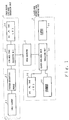
- Fig. 1 is a block diagram of an embodiment of the present invention.
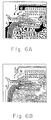
- an image-vector line-data generating unit 1 is constructed of: an image scanner 1-1 that automatically reads an original map, such as a topographical map or a circuit-diagram like that shown in Fig. 6A, and then issues an electrical signal; a pattern-recognition module 1-2 that receives the electrical signal issued from the image scanner 1-1 and generates a digital-image signal from the electrical signal thus received; a line-data image processing unit 1-3 that generates vector line data by extracting fine-line data from the digital-image signal --said signal having been generated by the pattern-recognition module 1-2, -- and prepares, for example, the line-data image shown in Fig.
- RAM (I) 1-4 which stores the vector line data (which has been prepared by the line-data image processing unit 1-3) as the L-file 2a for line-data image processing, which will be described later.
- "NSXPRES5000” is an automatic drawing system CAD of Shin-Nittetsu, Japan which can be used as the image-vector line-data generating unit 1.
- the data converter 2 has its input side connected with the image-vector line-data generating unit 1, and has its output side connected with the closed-area property-data preparing unit 3.
- the L-file 2a for line-data image processing is retrieved from the image-vector line-data generating unit 1. Then, line data of the L-file thus retrieved 2a is analyzed and issued as D-file 2b line data for closed-area-data image processing (which will be described later) to the closed-area property-data preparing unit 3.
- Common personal computers of, for example, Fujitsu, NEC, IBM, etc. can be used as the data converter 2.
- the closed-area property-data preparation unit 3 consists of a closed-area-data image processing unit 3-1; RAM (II) 3-2, in which the D-file 2b for closed-area-data image processing is stored; RAM (II) 3-2, which connects to the closed-area-data image processing unit 3-1; a keyboard 3-3, through which commands are input to execute interpolation of the line data in the D-file 2b for closed-area-data image processing, to allocate property to corresponding regions or points, to print the output and so forth and, a plotter 3-4 which prints the map information on the basis of print output data issued from the closed-area -data image processing unit 3-1.
- the closed-area property-data preparation unit 3 can be, for example, the ARC/INFO of ESRI of America.
- Fig. 2A is a block diagram of the L-file 2a for line-data image processing, the L-file 2a being stored in the RAM (I) 1-4 of the image-vector line-data generating unit 1.
- Fig. 2B is a block diagram of the D-file 2b for closed-area-data image processing, the D-file 2b being stored in the RAM (II) 3-2 of the closed-area property-data preparation unit 3.
- the L-file 2a for line-data image processing of Fig. 2A consists of one record data.
- This record represents a line that separately shows a contour or outline of an image, and consists of a header portion 21 and a data portion 22.
- the header portion 21 consists of a class portion 21-1 for showing the record's class; a code portion 21-2, for showing the configuration and the like of a line indicated by the record; and, a list portion 21-3 for showing the length of the data portion 22.
- this line data for example, the cross image shown in Fig.
- 14A may be represented by two sets of line data (lines A and B), wherein line A connects a point (xa-0, ya-0) and a point (xa-1, ya-1), and line B connects a point (xb-0, yb-0) and a point (xb-1, yb-1). Further, as shown in Fig. 14B, it is also possible to divide the line at an intersection point of the cross image into four pieces of line data (lines A, B, C and D). Moreover, the line data may also be represented by dashed lines, AB and DC.
- the line-data image processing unit 1-3 may, as needed, sequentially retrieve the L-file 2a for line-data image processing from the RAM (I) 1-4, and issue a graphical form, such as that shown in Fig. 6B, as data.
- the D-file 2b for closed-area-data image processing of Fig. 2B is quite different in file construction from the L-file 2a for line-data image processing of Fig. 2A, and has the same construction as that of, for example, a DLG file for handling the closed-area data. Namely, the D-file 2b for closed-area -data image processing of Fig.
- 2B consists of a header portion 2b-1 for storing data that indicates the file construction; a point-data portion 2b-2 for storing point data that indicates a bend or bent point of the polygonal line, and a line terminal thereof; an area-data portion 2b-3 for storing data that indicates at least one of the properties of the closed area; and, a line-data portion 2b-4 for storing the line data.
- the data converter 2 comprises a CPU 31 with microprocessor and ROM 32, in which a program is stored. Based on the program stored in the ROM 32, the CPU 31 transforms a data of the L-file 2a for line-data image processing into the D-file 2b for closed-area-data-image processing.
- step S1 the L-file 2a for line-data image processing is first read in step S1, followed by step S2, in which the number of elements is retrieved from the list portion 21-3 of the file-header portion 21 and stored in the register i. Then, the value of the register i is determined. When the value is not "0", there is the element to be read so that a step S5 follows. In this step S5, an element record i is retrieved so that element data in the leading portion of element i is retrieved and stored in register j. Then, in step S6, the value of register j is determined. When this value is any one of "1" to "7", steps S7 to S13 are executed, respectively.
- Coordinate data which is stored in a second location subsequent to the element data in the element record i, is then retrieved.
- the coordinate data thus retrieved is transferred to the line data portion 2b-4 of the D-file 2b for closed-area-data image processing, and written into a predetermined location.
- the values of register j represent a straight line, a single-bend polygonal line, a two-bend polygonal line, ..., a seven-bend polygonal line, and an eight-or-more bend polygonal line, respectively.
- step S6 if the value of register j is more than "7", the element type indicates non-line data. In this case, step 14 immediately follows.
- step S3 if the value of register i is "0", the entire the element record has already been retrieved, and thus, processing of one graphical form has been completed.
- step S15 follows, in which plane data is prepared. The procedures in this routine are thereby completed.
- step 51 the line date which is prepared on the D-file 2b for closed-area-data image processing is retrieved, and divided into line segments through a division process.
- the line data thus retrieved is divided (at points of contact with the remaining line data, and at points of intersection through which the retrieved line data is crossed by the remaining line data) into line segments free from such points of contact and intersection. Line-segment numbers are then allotted to the line segments thus obtained.
- Step S52 follows next.
- step S52 the types of starting and end points of each of the line segments are determined.
- the starting and end points of each of the line segments which have been divided at these points to produce line segments completely free from these points therein are classified as independent points (not connected to any line data), branch points (i.e., contact points) or midpoints (i.e., bends or bent points in the polygonal lines), and are then registered by category.
- step S53 these line segments are sorted based on the starting and end points.
- step S54 the line segments thus sorted are connected in a predetermined direction, either clockwise or counterclockwise. If the end point of the line segment is a branch point, there are a number of line segments each of which has the same starting point.
- step S55 the point type of end point of the segment thus connected is determined.
- connection processing of the line segments is completed so that a subsequent step S56 may follow.
- step S56 a plane-data number is allotted to the plane data constructed of a series of line segments thus connected. Such number-allotted plane data is then stored in the D-file 2b for closed-area-data image processing.
- step S55 if the end point of the connected line segment has different coordinates, and therefore a different point type, from the starting point of the first line segment, and further is not an isolated point, the processing procedures in the flowchart return to step S54 to permit a subsequent line segment to be connected.
- the closed-area-data image processing unit 3-1 of Fig. 1 may retrieve the plane data (which is transformed from the line data as described above and stored in the line-data portion 2b-4 of the D-file 2b for closed-area-data image processing) so as to have a graphical form of the map (such as that shown in Fig. 7) displayed on a CRT display unit (not shown).
- the CRT display unit may notify an operator by flashing a predetermined mark on each line discontinuity, the discontinuities being indicated in Fig. 7 by arrows A, B,..., F, respectively.
- the line discontinuities are eliminated by a correction process whereby lines are made continuous using a mouse or the like, the mouse (not shown) being connected to a cursor key (not shown) a keyboard 3-3.
- the line data which is thus transformed into correctly interpolated closed-area data, is again stored in the line-data portion 2b-4 of the D-file 2b for closed-area-data image processing.
- corresponding point data in the point-data portion 2b-2 of the same D-file is automatically corrected and stored again therein.
- the thus prepared D-file 2b for closed-area-data image processing of the RAM (II) is retrieved by the closed-area-data image processing unit 3-1 of Fig. 1, and output through the plotter 3-4 as map information.
- the image thus output may, for example, take the form of a land-use condition map such as that shown in Fig. 9.
- the present invention can accomplish such preparation of map information within a few days, whereas using the prior art several months may be required.
- the interpolation process used to fill discontinuities in the defective graphical map data is performed by using the closed-area property-data preparation unit 3.
- the closed-area property-data preparation unit 3 Even when preparing a land-use maps for relatively narrower prefectures (such as OKINAWA or TOTTORI) approximately 100,000 pieces of plane data are needed.
- several tens of display pictures are required for correcting the input data. If several tens of pictures are corrected using only one unit, too much time is required to enjoy the drastic reduction in operation time accomplished by automating the plane-data preparation step.
- Fig. 10 is a block diagram of the second embodiment of the present invention, wherein the same parts as those of the first embodiment of the present invention shown in Fig. 1 are denoted by the same reference numerals as those applied to the parts of the first embodiment.
- the data converter 2 is connected with a plurality of personal computers 4-1 (PC1), 4-2 (PC2), ..., 4-n (PCn).
- PC1 personal computers
- PC2 PC2
- PCn 4-n
- Fig. 11 is a block diagram of the above personal computers PCi.
- CPU 4-i-1 comprises a microprocessor and controls the whole system on the basis of a program stored in ROM 4-i-2.
- ROM 4-i-3 comprises an M-file 2c for closed-area-data correction processing and a storage area for works.
- a CRT i.e., a display unit with cathode-ray tube
- a mouse 4-i-5 that controls a cursor on a desired point on the screen of CRT 4-i-4, makes it possible to input a coordinate value for said point.
- Fig. 12A shows the D-file 2b for closed-area-data image processing shown in Fig 2B.
- Fig. 12B shows the data structure of the M-file 2c for closed-area-data correction processing, which file 2c is prepared on the basis of the D-file 2b for closed-area-data image processing described above.
- the M-file 2c for closed-area-data correction processing consists of a file-number portion 2b-1 that stores a file number for clarifying which D-file 2b is used in data retrieval; an isolated-point-data portion 2c-2 that stores predetermined data (such as for a small yellow circular mark) placed around the coordinate of an isolated point (a point of discontinuity) detected from the point data and the line data of the D-file 2b; and, a line-data portion 2c-4 that stores line data retrieved from the line data of the D-file 2b.
- predetermined data such as for a small yellow circular mark
- a step S1201 the D-file 2b for closed-area-data image processing is first read so that a file number corresponding to the D-file 2b thus read is prepared on the basis of the data of the header portion 2b-1 and stored in the file-number portion 2c-1 of the M-file 2c for closed-area-data correction processing.
- step S1202 next determines whether the file is in "END". If the file is not in "END", step 1203 follows, whereby the data of the D-file 2b is subsequently read to determine whether the data thus read consists of point data (i.e., data retrieved from the point-data portion 2b-2 of the D-file 2b) or line data (i.e., data retrieved from the line-data portion 2b-4 of the D-file 2b).
- point data i.e., data retrieved from the point-data portion 2b-2 of the D-file 2b
- line data i.e., data retrieved from the line-data portion 2b-4 of the D-file 2b
- step S1204 follows to determine whether the point data indicates an isolated point.
- This judgment also determines whether the number of line data items which connects one item of point data with another is two or more than two. If the number of line data is two, the point data in question corresponds to a bend or bent point in a polygonal line. If the number of line data items is three or more, the point data in question represents a contact point (i.e., a convergent point or the starting point of diversion). Therefore, in both cases described above, the point data in question is not identified as that of the isolated point. And, if the number of line data items from the point data is only one, such point data is identified as that of an isolated point.
- a step S1205 follows such that the coordinates of the isolated point are read.
- a step S1206 follows such that circle data, i.e., data for a circle (having the isolated point as its center and a predetermined radius, is prepared.
- the circle data is thus stored in the isolated-point-data portion 2c-2 of the M-file 2c for closed-area-data correction processing. Operation then returns to step S1202 described above.
- step S1204 If through the judgment performed in step S1204, the point data is not identified as that of an isolated point, operation immediately returns to the above step S1202.
- a step S1207 follows such that the line data is classified by type.
- the line data is classified as one of the following: a straight line (coordinate corresponding to a pair of points); a one-bend polygonal line (coordinates corresponding to three points); ...; a six-bend polygonal line (coordinates corresponding to seven points); or, an polygonal line with seven bends or more (coordinates corresponding to at least eight points).
- step S1208, S1209, ..., S1213, or S1214 is executed such that the coordinates of the line data are read and step S1208', S1209', ..., S1213', or S1214' follows respectively, whereby line data consisting of point-coordinate data thus read above is stored in the line-data portion 2c-3 of the M-file 2c for closed-area-data correction processing so as to permit the operation to return to step S1201.
- the operator identifies interrupted points, i.e., points of discontinuity in the graphical form of the map by means of circular marks that indicate where discontinuities occur. If a discontinuity is too small, making it too difficult for the operator to identify it, the point of discontinuity may be enlarged on the display and taken care of using the mouse through a process of interpolation.
- Data thus interpolated is stored as new line data in the line-data portion 2c-3 of the M-file 2c for closed-area-data correction processing. After data correction is completed, the new line data is retrieved by the data converter 2 and issued to the closed-area property-data preparation unit 3.
Landscapes
- Engineering & Computer Science (AREA)
- Physics & Mathematics (AREA)
- Theoretical Computer Science (AREA)
- General Physics & Mathematics (AREA)
- Software Systems (AREA)
- Geometry (AREA)
- General Engineering & Computer Science (AREA)
- Mathematical Physics (AREA)
- Educational Technology (AREA)
- Educational Administration (AREA)
- Business, Economics & Management (AREA)
- Ecology (AREA)
- Life Sciences & Earth Sciences (AREA)
- Remote Sensing (AREA)
- Computer Hardware Design (AREA)
- Computer Graphics (AREA)
- Data Mining & Analysis (AREA)
- Databases & Information Systems (AREA)
- Processing Or Creating Images (AREA)
- Image Processing (AREA)
- Instructional Devices (AREA)
Claims (6)
- Verfahren zum Herstellen von Kartendaten, wobei das Verfahren die Schritte umfaßt:zweidimensionale Vektorliniendaten (L-Datei) von durch Lesen einer Originalkarte erhaltenen Rasterdaten zu erzeugen,die zweidimensionalen Vektorliniendaten in geschlossene Bereichsdaten (D-Datei) umzuwandeln, indema) die Liniendaten in Liniensegmente unterteilt werden, die keine Kontakt- und Schnittpunkte aufweisen, und ihnen Liniensegmentenummern zugeordnet werden,b) Start- und Endpunkte jedes der Liniensegmente bestimmt werden,c) die Liniensegmente basierend auf Start- und Endpunkten sortiert werden und sie in einer vorbestimmten Richtung verbunden werden,d) die Verbindung von Liniensegmenten abgeschlossen wird, wenn ein Endpunkt eines Segments die gleichen Koordinaten wie der Startpunkt des ersten Segments aufweist,e) den so konstruierten vorläufigen geschlossenen Bereichsdaten einen Plandatennummer zugeordnet wird,f) Linienunterbrechungen durch einen von einem Operator durchgeführten Korrekturprozeß zum Erhalt geschlossener Bereichsdaten zu durchgehenden Linien verarbeitet zu werden,g) den geschlossenen Bereichsdaten regionale Eigenschaften anzeigende Merkmalsdaten zugewiesen werden, undh) die geschlossenen Bereichsdaten gespeichert werden, die angezeigt und/oder ausgedruckt werden können.
- Vorrichtung zum Herstellen von Kartendaten, wobei die Vorrichtung umfaßt:eine Erzeugungseinheit (1) für Bildvektorliniendaten, die zweidimensionale Vektorliniendaten (L-Datei) aus durch Lesen einer Originalkarte erhaltenen Rasterdaten erzeugt,einen Datenumformer (2), der die zweidimensionalen Vektorliniendaten in geschlossene Bereichsdaten (D-Datei) umwandelt, wobei der Datenumformer umfaßt:a) Mittel zum Unterteilen der Liniendaten in Liniensegmente, die keine Kontakt- und Schnittpunkte aufweisen, undb) Mittel, um denselben Liniensegmentnummern zuzuordnen, die Start- und Endpunkte jedes der Liniensegmente bestimmen,c) Mittel zum Sortieren der Liniensegmente basierend auf Start- und Endpunkten und Verbinden derselben in einer vorbestimmten Richtung,d) Mittel zum Vervollständigen der Verbindung von Liniensegmenten, wenn ein Endpunkt eines Segments die gleichen Koordinaten wie der Startpunkt des ersten Segments aufweist,e) Mittel, um den so konstruierten vorläufigen geschlossenen Bereichsdaten eine Plandatennummer zuzuweisen;eine geschlossene Datenbereich-Verarbeitungseinheit (3) zum Verarbeiten von Linienunterbrechungen zu durchgehenden Linien durch einen von einem Operator durchgeführten Korrekturprozeß zum Erhalt geschlossener Bereichsdaten,Mittel, um den geschlossenen Bereichsdaten Merkmalsdaten zuzuweisen, die regionale Eigenschaften anzeigen, undMittel zum Speichern der genannten geschlossenen Bereichsdaten, die angezeigt und/oder gedruckt werden können.
- Vorrichtung zum Herstellen von Kartendaten nach Anspruch 2, bei derdie durch die Erzeugungseinheit (1) für Bildvektorliniendaten ausgegebenen Liniendaten aus einem eine Umrißlinie eines Bildes anzeigenden einfachen Datensatz besteht, wobei der eine Datensatz aus einem Kopfteil (21) und einem Datenteil (22) besteht, wobei der Kopfteil aus einem die Klasse des Datensatzes anzeigenden Klassenteil (21-1), einem die Linienform des Datensatzes anzeigenden Codeteil (21-2), und einem die Zahl von Elementen in dem Datenteil anzeigenden Listenteil (21-3) besteht, und wobei der Datenteil aus einer Vielzahl von Parameterteilen (i=1..n) zum Speichern von eine Linie darstellenden Koordinatendaten als einen Elementdatensatz besteht.
- Vorrichtung zum Herstellen von Kartendaten nach Anspruch 2, bei derdie durch den Datenumformer (2) ausgegebenen geschlossenen Bereichsdaten auf einer DLG-Datei basieren und aus einem Kopfteil (2b-1) zum Speichern von eine Dateikonfiguration anzeigenden Daten, einem Punktdatenteil (2b-2) zum Speichern von Punktdaten, die oberen Punkt und Endpunkt in einer graphischen Linie anzeigen, einen Bereichsdatenteil (2b-3) zum Speichern von Daten, die wenigstens ein Merkmal eines geschlossenen Bereichs anzeigen, und einem Liniendatenteil (2b-4) zum Speichern von Liniendaten bestehen.
- Vorrichtung zum Herstellen von Kartendaten nach Anspruch 2, bei derder Datenumformer (2) geschlossene Bereichsdaten durch Auslesen der Zahl von Elementdatensätzen aus dem Listenteil in dem Kopfteil erzeugt, indem von der Erzeugungseinheit (1) für Bildvektorliniendaten ausgegebene, einen Datensatz umfassende Liniendaten ausgelesen werden, nacheinander die Elementdatensätze von dem Datenteil ausgelesen werden, Elementtypdaten am Kopf des Elementdatensatzes ausgelesen werden, nach den Elementtypdaten ausgelesene Koordinatendaten analysiert werden und die analysierten Koordinatendaten in einem vorbestimmten Bereich des Liniendatenteils in Übereinstimmung mit der Dateikonfiguration der DLG-Datei gespeichert werden.
- Vorrichtung zum Herstellen von Kartendaten wie in Anspruch 2 ausgeführt, bei der:die Vorrichtung weiter eine Vielzahl von Personalcomputern (4-1, 4-2, ..., 4-n) verbunden mit dem Datenumformer (2) zum Vervollständigen der vorläufigen geschlossenen Bereichsdaten als geschlossene Bereichsdaten durch Verarbeitung von Linienunterbrechungen aufweist, wobei die so vervollständigten geschlossenen Bereichsdaten von einer Vielzahl der Personalcomputer (4-1, 4-2, ..., 4-n) ausgegeben werden; undder Datenumformer (2) die vorläufigen geschlossenen Bereichsdaten erzeugt, die wenigstens aus Punktdaten und Liniendaten bestehen, welche auf der Grundlage von aus der Erzeugungseinheit (1) für Bildvektorliniendaten ausgegebenen Vektorliniendaten erzeugt werden, die vorläufigen geschlossenen Bereichsdaten in eine Vielzahl von Teilen aus vorläufigen geschlossenen Bereichsdaten unterteilt, vorbestimmte Anzeigedaten unterbrochenen Punktdaten für die Liniendaten zuweist, die jeden der Teile der so unterteilten vorläufigen geschlossenen Bereichsdaten bilden, die Teile von vorläufigen geschlossenen Bereichsdaten an jeden der Personalcomputer (4-1, 4-2, ..., 4-n) ausgibt und geschlossene Bereichsdaten an die Erzeugungseinheit (3) für geschlossene Bereichsdaten ausgibt.
Applications Claiming Priority (3)
| Application Number | Priority Date | Filing Date | Title |
|---|---|---|---|
| JP4870692 | 1992-03-05 | ||
| JP4048706A JP2770097B2 (ja) | 1991-06-24 | 1992-03-05 | 地図データ作成方法及びその装置 |
| JP48706/92 | 1992-03-05 |
Publications (3)
| Publication Number | Publication Date |
|---|---|
| EP0559294A2 EP0559294A2 (de) | 1993-09-08 |
| EP0559294A3 EP0559294A3 (en) | 1995-05-10 |
| EP0559294B1 true EP0559294B1 (de) | 2000-10-18 |
Family
ID=12810765
Family Applications (1)
| Application Number | Title | Priority Date | Filing Date |
|---|---|---|---|
| EP93200751A Expired - Lifetime EP0559294B1 (de) | 1992-03-05 | 1993-03-05 | Verfahren und Vorrichtung zur Vorbereitung von Landkartendaten mit regionalen Eigenschaften |
Country Status (6)
| Country | Link |
|---|---|
| US (1) | US5377102A (de) |
| EP (1) | EP0559294B1 (de) |
| KR (1) | KR0156270B1 (de) |
| AU (1) | AU663566B2 (de) |
| DE (1) | DE69329565T2 (de) |
| GB (1) | GB2266024B (de) |
Families Citing this family (33)
| Publication number | Priority date | Publication date | Assignee | Title |
|---|---|---|---|---|
| DE69425234T2 (de) * | 1993-12-27 | 2000-11-30 | Nissan Motor Co., Ltd. | Fahrzeugzielführungsvorrichtung und -verfahren unter Verwendung einer Anzeigeeinheit |
| US5793310A (en) * | 1994-02-04 | 1998-08-11 | Nissan Motor Co., Ltd. | Portable or vehicular navigating apparatus and method capable of displaying bird's eye view |
| TW371334B (en) * | 1994-03-18 | 1999-10-01 | Hitachi Ltd | Method for retrieving database with image information |
| US5768439A (en) * | 1994-03-23 | 1998-06-16 | Hitachi Software Engineering Co., Ltd. | Image compounding method and device for connecting a plurality of adjacent images on a map without performing positional displacement at their connections boundaries |
| US5748808A (en) * | 1994-07-13 | 1998-05-05 | Yashima Electric Co., Ltd. | Image reproducing method and apparatus capable of storing and reproducing handwriting |
| EP0693739A3 (de) * | 1994-07-13 | 1997-06-11 | Yashima Denki Kk | Zur Handschriftspeicherung und -wiedergabe geeignetes Verfahren und Apparat |
| US5987173A (en) * | 1995-03-27 | 1999-11-16 | Nippon Steel Corporation | Interactive drawing recognition processing method and apparatus thereof |
| JP3568621B2 (ja) | 1995-04-20 | 2004-09-22 | 株式会社日立製作所 | 地図表示装置 |
| US5761385A (en) * | 1995-09-05 | 1998-06-02 | Loral Defense Systems | Product and method for extracting image data |
| US5771169A (en) * | 1996-08-29 | 1998-06-23 | Case Corporation | Site-specific harvest statistics analyzer |
| US5928304A (en) * | 1996-10-16 | 1999-07-27 | Raytheon Company | Vessel traffic system |
| KR100663606B1 (ko) * | 1999-12-17 | 2007-01-02 | 주식회사 케이티 | 지도정보 좌표값을 이용한 다조건 최적경로 산출방법 |
| WO2001080099A1 (en) * | 2000-04-14 | 2001-10-25 | The Orton Family Foundation | Integrated system for and method of supporting spatial decision making and land-use scenario analysis |
| US6401041B1 (en) * | 2000-05-11 | 2002-06-04 | Clayton Petersen | Automated graphical representation of agricutural information |
| US6385533B1 (en) | 2001-01-03 | 2002-05-07 | Navigation Technologies Corp. | Method and system using dynamic profiling in a mobile environment for collecting data for a geographic database |
| JP4172941B2 (ja) * | 2002-03-01 | 2008-10-29 | 日立ソフトウエアエンジニアリング株式会社 | 土地区画データ作成方法および装置 |
| US8108429B2 (en) | 2004-05-07 | 2012-01-31 | Quest Software, Inc. | System for moving real-time data events across a plurality of devices in a network for simultaneous data protection, replication, and access services |
| US7565661B2 (en) | 2004-05-10 | 2009-07-21 | Siew Yong Sim-Tang | Method and system for real-time event journaling to provide enterprise data services |
| JP4436186B2 (ja) * | 2004-05-12 | 2010-03-24 | アルパイン株式会社 | ナビゲーション装置及び地図表示方法 |
| US7680834B1 (en) | 2004-06-08 | 2010-03-16 | Bakbone Software, Inc. | Method and system for no downtime resychronization for real-time, continuous data protection |
| US7979404B2 (en) | 2004-09-17 | 2011-07-12 | Quest Software, Inc. | Extracting data changes and storing data history to allow for instantaneous access to and reconstruction of any point-in-time data |
| JP2006099236A (ja) * | 2004-09-28 | 2006-04-13 | Toshiba Corp | 分類支援装置、分類支援方法及び分類支援プログラム |
| US7904913B2 (en) | 2004-11-02 | 2011-03-08 | Bakbone Software, Inc. | Management interface for a system that provides automated, real-time, continuous data protection |
| US9274765B2 (en) * | 2005-05-12 | 2016-03-01 | Drawing Management, Inc. | Spatial graphical user interface and method for using the same |
| US7689602B1 (en) | 2005-07-20 | 2010-03-30 | Bakbone Software, Inc. | Method of creating hierarchical indices for a distributed object system |
| US7788521B1 (en) | 2005-07-20 | 2010-08-31 | Bakbone Software, Inc. | Method and system for virtual on-demand recovery for real-time, continuous data protection |
| US8131723B2 (en) | 2007-03-30 | 2012-03-06 | Quest Software, Inc. | Recovering a file system to any point-in-time in the past with guaranteed structure, content consistency and integrity |
| US8364648B1 (en) | 2007-04-09 | 2013-01-29 | Quest Software, Inc. | Recovering a database to any point-in-time in the past with guaranteed data consistency |
| KR100857122B1 (ko) * | 2007-04-12 | 2008-09-05 | 주식회사 유니디스플레이 | 채널 오프셋 전압 보상 방법 및 이를 이용한 액정 패널구동용 컬럼 구동 회로 |
| KR100842010B1 (ko) * | 2007-06-20 | 2008-06-27 | 태양정보시스템(주) | 항공사진의 도화를 이용한 주거용 구조물의 분류방법 |
| KR100842011B1 (ko) * | 2007-06-20 | 2008-06-27 | 태양정보시스템(주) | 항공사진의 도화 및 고도를 이용한 주거용 구조물의 분류방법 |
| US9418110B1 (en) * | 2008-06-30 | 2016-08-16 | Emc Corporation | Intelligent, scalable, low-overhead mechanism for data retrieval in a distributed network environment |
| EP2902909A4 (de) * | 2012-09-28 | 2016-06-01 | Nec Corp | Verteilte speichervorrichtung, speicherknoten, datenbereitstellungsverfahren und programm |
Family Cites Families (7)
| Publication number | Priority date | Publication date | Assignee | Title |
|---|---|---|---|---|
| DE3381833D1 (de) * | 1982-03-31 | 1990-10-04 | Gen Electric | Verfahren und geraet zur sehbildverarbeitung und zur eckpunktsortierung in einem sehbild-verarbeitungssystem. |
| JPH0690596B2 (ja) * | 1985-04-30 | 1994-11-14 | 日本電装株式会社 | 電子地図表示装置 |
| FR2590702B1 (fr) * | 1985-11-26 | 1990-07-27 | Thomson Csf | Procede de pontage entre elements de contours dans une image |
| AU583202B2 (en) * | 1987-02-06 | 1989-04-20 | Fujitsu Limited | Method and apparatus for extracting pattern contours in image processing |
| EP0346491A4 (en) * | 1987-12-28 | 1992-08-19 | Aisin Aw Co., Ltd. | A display unit of navigation system |
| IE61778B1 (en) * | 1989-01-04 | 1994-11-30 | Emyville Enterprises | Image processing |
| US5150295A (en) * | 1990-05-22 | 1992-09-22 | Teledyne Industries, Inc. | Computerized system for joining individual maps into a single map product |
-
1993
- 1993-03-03 US US08/025,984 patent/US5377102A/en not_active Expired - Lifetime
- 1993-03-05 KR KR1019930003337A patent/KR0156270B1/ko not_active Expired - Fee Related
- 1993-03-05 EP EP93200751A patent/EP0559294B1/de not_active Expired - Lifetime
- 1993-03-05 GB GB9304520A patent/GB2266024B/en not_active Expired - Fee Related
- 1993-03-05 AU AU34031/93A patent/AU663566B2/en not_active Ceased
- 1993-03-05 DE DE69329565T patent/DE69329565T2/de not_active Expired - Lifetime
Also Published As
| Publication number | Publication date |
|---|---|
| AU3403193A (en) | 1993-09-09 |
| DE69329565T2 (de) | 2001-05-31 |
| GB9304520D0 (en) | 1993-04-21 |
| EP0559294A3 (en) | 1995-05-10 |
| GB2266024B (en) | 1995-05-24 |
| EP0559294A2 (de) | 1993-09-08 |
| AU663566B2 (en) | 1995-10-12 |
| KR0156270B1 (ko) | 1998-11-16 |
| DE69329565D1 (de) | 2000-11-23 |
| KR930020297A (ko) | 1993-10-19 |
| US5377102A (en) | 1994-12-27 |
| GB2266024A (en) | 1993-10-13 |
Similar Documents
| Publication | Publication Date | Title |
|---|---|---|
| EP0559294B1 (de) | Verfahren und Vorrichtung zur Vorbereitung von Landkartendaten mit regionalen Eigenschaften | |
| US5359526A (en) | Terrain and culture generation system and method | |
| Li et al. | A natural principle for the objective generalization of digital maps | |
| de By et al. | Principles of geographic information systems | |
| US5684940A (en) | Computer-implemented method and apparatus for automatically labeling area regions of maps using two-step label placing procedure and for curved labeling of point features | |
| US4744033A (en) | Electronic display system | |
| US5988853A (en) | Method for placing names for point-features on a map based on a plane sweeping technique | |
| EP0619554A2 (de) | Verfahren zur Geographischausrichtung von bitorganisierten Raumkoordinaten | |
| JP5081311B2 (ja) | 地図情報処理装置、地図情報処理方法、地図情報処理プログラム、及び記録媒体 | |
| US5519817A (en) | Method and apparatus for searching line data in graphic data base system | |
| JP2004101780A (ja) | 位置座標補正処理装置及び処理方法 | |
| KR100195018B1 (ko) | 수치지도 형상데이터 합성시 그 명칭 처리방법 | |
| CN117556158A (zh) | 耦合地名标签与等值线的用户周边地点可视化方法及系统 | |
| JP2770097B2 (ja) | 地図データ作成方法及びその装置 | |
| CN110132233A (zh) | 一种基于点云数据的cass环境下现状地形图绘图方法 | |
| JP3492185B2 (ja) | 電子地図の作成方法と更新方法 | |
| JP2004177862A (ja) | 地図位置補正装置および方法 | |
| JP3692159B2 (ja) | シンボル位置自動補正方法 | |
| KHAKHAR et al. | THE CHOROLOGICAL INFORMATION PROCESSING SYSTEM NORMAP | |
| JP2000047577A (ja) | 電子地図の表示方法と装置 | |
| JPH0812548B2 (ja) | 図面の表示方法 | |
| JP2004355505A (ja) | 時空間データ管理装置及び方法 | |
| Bannon | Developing a Cartographic Geo-Code System (CAGES) | |
| Dangennond | 17 A review of digital data commonly availableand some of the practical problems ofentering them into a GIS | |
| Wiltshire | Selected papers in the applied computer sciences, 1990 |
Legal Events
| Date | Code | Title | Description |
|---|---|---|---|
| PUAI | Public reference made under article 153(3) epc to a published international application that has entered the european phase |
Free format text: ORIGINAL CODE: 0009012 |
|
| AK | Designated contracting states |
Kind code of ref document: A2 Designated state(s): DE FR |
|
| PUAL | Search report despatched |
Free format text: ORIGINAL CODE: 0009013 |
|
| AK | Designated contracting states |
Kind code of ref document: A3 Designated state(s): DE FR |
|
| 17P | Request for examination filed |
Effective date: 19951108 |
|
| 17Q | First examination report despatched |
Effective date: 19990216 |
|
| RIC1 | Information provided on ipc code assigned before grant |
Free format text: 6G 06T 1/00 A |
|
| GRAG | Despatch of communication of intention to grant |
Free format text: ORIGINAL CODE: EPIDOS AGRA |
|
| GRAG | Despatch of communication of intention to grant |
Free format text: ORIGINAL CODE: EPIDOS AGRA |
|
| GRAH | Despatch of communication of intention to grant a patent |
Free format text: ORIGINAL CODE: EPIDOS IGRA |
|
| GRAH | Despatch of communication of intention to grant a patent |
Free format text: ORIGINAL CODE: EPIDOS IGRA |
|
| GRAA | (expected) grant |
Free format text: ORIGINAL CODE: 0009210 |
|
| AK | Designated contracting states |
Kind code of ref document: B1 Designated state(s): DE FR |
|
| REF | Corresponds to: |
Ref document number: 69329565 Country of ref document: DE Date of ref document: 20001123 |
|
| ET | Fr: translation filed | ||
| PLBE | No opposition filed within time limit |
Free format text: ORIGINAL CODE: 0009261 |
|
| STAA | Information on the status of an ep patent application or granted ep patent |
Free format text: STATUS: NO OPPOSITION FILED WITHIN TIME LIMIT |
|
| 26N | No opposition filed | ||
| PGFP | Annual fee paid to national office [announced via postgrant information from national office to epo] |
Ref country code: FR Payment date: 20100331 Year of fee payment: 18 |
|
| PGFP | Annual fee paid to national office [announced via postgrant information from national office to epo] |
Ref country code: DE Payment date: 20100410 Year of fee payment: 18 |
|
| REG | Reference to a national code |
Ref country code: FR Ref legal event code: ST Effective date: 20111130 |
|
| PG25 | Lapsed in a contracting state [announced via postgrant information from national office to epo] |
Ref country code: FR Free format text: LAPSE BECAUSE OF NON-PAYMENT OF DUE FEES Effective date: 20110331 Ref country code: DE Free format text: LAPSE BECAUSE OF NON-PAYMENT OF DUE FEES Effective date: 20111001 |
|
| REG | Reference to a national code |
Ref country code: DE Ref legal event code: R119 Ref document number: 69329565 Country of ref document: DE Effective date: 20111001 |