EP0559568A1 - Verankerung einer Struktur aus Verbundwerkstoff auf einer metallischen Struktur - Google Patents
Verankerung einer Struktur aus Verbundwerkstoff auf einer metallischen Struktur Download PDFInfo
- Publication number
- EP0559568A1 EP0559568A1 EP93400564A EP93400564A EP0559568A1 EP 0559568 A1 EP0559568 A1 EP 0559568A1 EP 93400564 A EP93400564 A EP 93400564A EP 93400564 A EP93400564 A EP 93400564A EP 0559568 A1 EP0559568 A1 EP 0559568A1
- Authority
- EP
- European Patent Office
- Prior art keywords
- metal
- composite materials
- composite
- anchoring
- vertical
- Prior art date
- Legal status (The legal status is an assumption and is not a legal conclusion. Google has not performed a legal analysis and makes no representation as to the accuracy of the status listed.)
- Granted
Links
Images



Classifications
-
- B—PERFORMING OPERATIONS; TRANSPORTING
- B63—SHIPS OR OTHER WATERBORNE VESSELS; RELATED EQUIPMENT
- B63B—SHIPS OR OTHER WATERBORNE VESSELS; EQUIPMENT FOR SHIPPING
- B63B29/00—Accommodation for crew or passengers not otherwise provided for
- B63B29/02—Cabins or other living spaces; Construction or arrangement thereof
-
- B—PERFORMING OPERATIONS; TRANSPORTING
- B63—SHIPS OR OTHER WATERBORNE VESSELS; RELATED EQUIPMENT
- B63B—SHIPS OR OTHER WATERBORNE VESSELS; EQUIPMENT FOR SHIPPING
- B63B73/00—Building or assembling vessels or marine structures, e.g. hulls or offshore platforms
- B63B73/40—Building or assembling vessels or marine structures, e.g. hulls or offshore platforms characterised by joining methods
-
- F—MECHANICAL ENGINEERING; LIGHTING; HEATING; WEAPONS; BLASTING
- F16—ENGINEERING ELEMENTS AND UNITS; GENERAL MEASURES FOR PRODUCING AND MAINTAINING EFFECTIVE FUNCTIONING OF MACHINES OR INSTALLATIONS; THERMAL INSULATION IN GENERAL
- F16B—DEVICES FOR FASTENING OR SECURING CONSTRUCTIONAL ELEMENTS OR MACHINE PARTS TOGETHER, e.g. NAILS, BOLTS, CIRCLIPS, CLAMPS, CLIPS OR WEDGES; JOINTS OR JOINTING
- F16B3/00—Key-type connections; Keys
- F16B3/005—Key-type connections; Keys the key being formed by solidification of injected material
-
- B—PERFORMING OPERATIONS; TRANSPORTING
- B63—SHIPS OR OTHER WATERBORNE VESSELS; RELATED EQUIPMENT
- B63B—SHIPS OR OTHER WATERBORNE VESSELS; EQUIPMENT FOR SHIPPING
- B63B5/00—Hulls characterised by their construction of non-metallic material
- B63B5/24—Hulls characterised by their construction of non-metallic material made predominantly of plastics
- B63B2005/242—Hulls characterised by their construction of non-metallic material made predominantly of plastics made of a composite of plastics and other structural materials, e.g. wood or metal
- B63B2005/245—Hulls characterised by their construction of non-metallic material made predominantly of plastics made of a composite of plastics and other structural materials, e.g. wood or metal made of a composite of plastics and metal
Definitions
- the present invention relates to a method for anchoring a composite material structure on a metallic structure, in particular for assembling composite material superstructures on a metallic ship hull.
- Assembly processes are known where the superstructures made of composite materials are assembled by bolting onto the steel hull.
- the state of the art is naturally oriented towards these processes since the direct welding of composite materials on a metal structure is not feasible.
- the fatigue strength of the bolted connection is often limited in the case of large structures.
- assembly by bolting alone is a source of reliefs unacceptable for the equivalent radar signature in the case of military applications.
- the object of the invention is to eliminate the drawbacks of bolting assembly by proposing a method for anchoring a composite material structure to a metallic structure and thus allowing the assembly of fully finished and partially pre-equipped composite structures in workshops. specific on metallic structures.
- the invention provides a method of anchoring a structure of composite materials of the monolithic type or of the sandwich type on a metal structure, characterized in that it is wedged, by means of a hardenable cast material, at the minus one shoulder on the end anchored with a structure in composite materials, between two metal sections, integral with a metal structure at one of their ends and converging towards their other free end.
- the metal profiles are convergent by folding inwards of their free end or by the inclination of at least one of the two profiles towards the second vertical at its free end.
- the composite material structure comprises at its anchored end a double shoulder by draping with strata of monolithic U-shaped composite materials.
- the structure in composite materials of the monolithic type deviates before its end anchored inwardly to ensure the coplanarity of the exterior surface of the structure in composite materials of the monolithic type and of the exterior surface of the inclined metal profile.
- the structure of composite materials of the sandwich type comprises a narrowing before its anchored end composed of monolithic composite materials, to ensure the coplanarity of the exterior surface of the structure of composite materials of the sandwich type and of the exterior surface. of the inclined metal profile.
- the curable cast material is preferably a resin, a loaded resin or a mortar.
- the anchored end before anchoring with the hardenable cast material, is positioned relative to the inclined profile, to the vertical profile and to the metal structure, by means of bolting between a machined counter plate. as an undercut and an extension of the vertical metal profile enclosing a portion of the monolithic type of the composite material structure.
- the method is advantageously applied to the assembly of superstructures made of composite materials on a metal hull of a ship or vice versa.
- the method is also advantageously applied to the assembly of bridges or partitions or else to transport modules or frames made of composite materials with a floor made of metallic material.
- FIG. 1 a ship is shown schematically in cross section to illustrate the application of the invention to the assembly of composite superstructures 1 on a metal ship hull 2.
- this process can be applied to all cases of heterogeneous assemblies of composite materials and metal parts.
- FIGS. 2 and 3 there is a possible embodiment of the method according to the invention respectively for a composite structure of the monolithic type and a composite structure of the sandwich type.
- the composite structure designated under the reference sign 6 is draped at its anchored end 5, to give a double shoulder 12, of additional U-shaped strata advantageously composed of a complex of monolithic composite materials made of glass fibers, carbon or aramid impregnated with resin.
- the composite structure 6 if it is of the monolithic type as shown in FIGS. 2, 4 and 6 can also preferably be produced in this way.
- this structure comprises a core 19 generally made of balsa or polychloride foam. vinyl glued in sandwich between two skins in fiberglass, carbon or aramid impregnated with resin 20 and 20 '.
- the composite structure 6 with the double shoulder 12 thus obtained is wedged by means of a hardenable cast material 3 between the two metal sections 7 and 8 which are therefore folded at their free end 11 in the form of a dovetail.
- the metal sections 7 and 8 being integral with the metal structure 9, for example by welding, the composite structure 6 is thus ideally anchored on the metal structure 9.
- the anchoring by this double wedging will be effective even using a curable cast material 3 which does not adhere either to the composite structure 6 or to the metal profiles 7 and 8 or even to the metal structure 9.
- This curable casting material 3 is chosen so as to have maximum fluidity during casting and a high mechanical resistance after curing.
- a resin for example epoxy or polyester, resin possibly charged with glass microbeads but also any kind of mortar such as cement, concrete or plaster.
- the junction between the metal sections 7 and 8 and the composite structure 6 is covered with a sealant 18 for considerations of the external atmosphere (hygiene, humidity or protection against ultraviolet rays) but also to allow if necessary optimal pressurization of parts whose partitions would be formed from the composite structure 6.
- Such an embodiment can be applied to the installation of partitions or walls inside a ship as shown in detail A in FIG. 1.
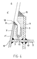
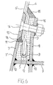
- Figures 4 and 5 respectively represent for a composite structure 6 of the monolithic type and a composite structure 6 of the sandwich type, another embodiment of the anchoring method according to the invention.
- the composite structure 6 is further doubly supported by a U-shaped composite layup for the composite structure 6 of the monolithic type as shown in FIG. 4 while FIG. 5 represents a single shoulder 4 made of monolithic composite materials for a composite structure 6 of the sandwich type.
- the core 19 of the sandwich structure is not extended to the anchored end 5 of this structure, the latter being preferably composed of composite materials of the monolithic type.
- This single shoulder 4 or double 12 is again wedged by means of the hardenable casting material 3 between the two sections 7 and 8 integral with the metal structure 9 and one of which 7 is inclined towards the second vertical 8 so to ensure the second jamming.
- This type of embodiment turns out to be particularly advantageous in connections at the level of the inclined planking of ship hulls, as shown in detail B in FIG. 1.
- the composite structure 6 of the monolithic type deviates before its anchored end 5 inwards to ensure the coplanarity of the external surface 6 ′ of the structure of composite materials 6 of the monolithic type and of the outer surface 7 ′ of the inclined metal profile 7 as shown in FIG. 4.
- the sandwich material structure 6 of the sandwich type has a constriction 13 before its anchored end 5, still composed of monolithic composite materials, to again ensure the coplanarity of the exterior surface 6 'of the structure of composite materials 6 of the sandwich type and of the external surface 7 ′ of the inclined metal profile 7.
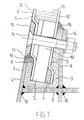
- FIGS. 6 and 7 embodiments are presented which are respectively the variants with bolts 14 of the embodiments of FIGS. 4 and 5.
- This bolting 14 can if necessary consolidate the anchoring by enclosing a portion 17 of the monolithic type of the composite structure 6 between an extension 16 of the vertical metal profile 8 and a counter plate machined in undercut 15, the intermediate part being filled with the curable casting material 3.
- this bolting 14 is used above all for positioning and temporarily maintaining the composite structure 6 between the two inclined metal profiles 7 and vertical 8 and the metal structure 9 before the casting of hardenable casting material 3.
- this counter plate 15 also avoids any possibility of creep of the sealant 18, the composite structure 6 conforming to this aim at best the trapezoidal shape of the internal face of the counter plate machined in undercut 15.
- Such superstructures for ships generally have a length of around 50 meters for a final mass of all the undeveloped superstructures of around 100 tonnes.
- the composite superstructures 1 are positioned in height and width between the inclined metal 7 and vertical 8 and the metal structure 9 composing the metal plating of the ship, with the bolting 14.
- curable casting material 3 resin known commercially under the name of "Urethane Acrylate Crestomer 1152 PA"
- the extension 16 can then be drilled against, if it is desired to replace a bolt 14, after the hardening cast material 3 has solidified.
- the method can be applied to any assembly of bridges or partitions or more generally to that of transport modules or frames made of composite materials with a floor made of metallic material.
Landscapes
- Engineering & Computer Science (AREA)
- Mechanical Engineering (AREA)
- Chemical & Material Sciences (AREA)
- Combustion & Propulsion (AREA)
- Ocean & Marine Engineering (AREA)
- Architecture (AREA)
- Structural Engineering (AREA)
- General Engineering & Computer Science (AREA)
- Bridges Or Land Bridges (AREA)
- Laminated Bodies (AREA)
- Load-Bearing And Curtain Walls (AREA)
- Joining Of Building Structures In Genera (AREA)
Applications Claiming Priority (2)
| Application Number | Priority Date | Filing Date | Title |
|---|---|---|---|
| FR9202640A FR2688275A1 (fr) | 1992-03-05 | 1992-03-05 | Procede d'ancrage d'une structure en materiaux composites sur une structure metallique. |
| FR9202640 | 1992-03-05 |
Publications (2)
| Publication Number | Publication Date |
|---|---|
| EP0559568A1 true EP0559568A1 (de) | 1993-09-08 |
| EP0559568B1 EP0559568B1 (de) | 1995-12-06 |
Family
ID=9427386
Family Applications (1)
| Application Number | Title | Priority Date | Filing Date |
|---|---|---|---|
| EP93400564A Expired - Lifetime EP0559568B1 (de) | 1992-03-05 | 1993-03-04 | Verankerung einer Struktur aus Verbundwerkstoff auf einer metallischen Struktur |
Country Status (5)
| Country | Link |
|---|---|
| EP (1) | EP0559568B1 (de) |
| DE (1) | DE69300927T2 (de) |
| ES (1) | ES2083256T3 (de) |
| FR (1) | FR2688275A1 (de) |
| TW (1) | TW212160B (de) |
Cited By (1)
| Publication number | Priority date | Publication date | Assignee | Title |
|---|---|---|---|---|
| US7223457B1 (en) | 1999-11-04 | 2007-05-29 | Basf Aktiengesellschaft | Composite elements |
Families Citing this family (3)
| Publication number | Priority date | Publication date | Assignee | Title |
|---|---|---|---|---|
| DE19825083A1 (de) | 1998-06-05 | 1999-12-09 | Basf Ag | Verbundelemente enthaltend kompakte Polyisocyanat-Polyadditionsprodukte |
| DE19914420A1 (de) | 1999-03-30 | 2000-10-05 | Basf Ag | Verbundelemente enthaltend Polyisocyanat-Polyadditionsprodukte |
| DE20103205U1 (de) | 2001-02-23 | 2001-09-20 | Hüppe GmbH & Co., 26160 Bad Zwischenahn | Befestigungselement, insbesondere für Bade- oder Duschwanne, Bade- oder Duschwanne |
Citations (4)
| Publication number | Priority date | Publication date | Assignee | Title |
|---|---|---|---|---|
| CH472626A (fr) * | 1967-02-08 | 1969-05-15 | H Beguin Gilbert | Procédé d'assemblage d'un matériau en feuille et d'un profilé, dispositif obtenu par ce procédé et application du procédé |
| CH490618A (de) * | 1968-12-20 | 1970-05-15 | Robert Schenk Fahrzeugfabrik F | Einrichtung zum Zusammenfügen aneinanderstossender Elemente |
| DE2416898A1 (de) * | 1974-04-06 | 1975-10-09 | Gmoehling Leichtmetall | Verfahren zur befestigung von blechen oder winkeln in einem profil |
| FR2629149A1 (fr) * | 1988-03-28 | 1989-09-29 | Ecia Equip Composants Ind Auto | Dispositif d'assemblage de pieces, notamment en matieres synthetiques, a l'aide d'une resine |
-
1992
- 1992-03-05 FR FR9202640A patent/FR2688275A1/fr active Granted
- 1992-04-10 TW TW081102775A patent/TW212160B/zh active
-
1993
- 1993-03-04 DE DE69300927T patent/DE69300927T2/de not_active Expired - Lifetime
- 1993-03-04 ES ES93400564T patent/ES2083256T3/es not_active Expired - Lifetime
- 1993-03-04 EP EP93400564A patent/EP0559568B1/de not_active Expired - Lifetime
Patent Citations (4)
| Publication number | Priority date | Publication date | Assignee | Title |
|---|---|---|---|---|
| CH472626A (fr) * | 1967-02-08 | 1969-05-15 | H Beguin Gilbert | Procédé d'assemblage d'un matériau en feuille et d'un profilé, dispositif obtenu par ce procédé et application du procédé |
| CH490618A (de) * | 1968-12-20 | 1970-05-15 | Robert Schenk Fahrzeugfabrik F | Einrichtung zum Zusammenfügen aneinanderstossender Elemente |
| DE2416898A1 (de) * | 1974-04-06 | 1975-10-09 | Gmoehling Leichtmetall | Verfahren zur befestigung von blechen oder winkeln in einem profil |
| FR2629149A1 (fr) * | 1988-03-28 | 1989-09-29 | Ecia Equip Composants Ind Auto | Dispositif d'assemblage de pieces, notamment en matieres synthetiques, a l'aide d'une resine |
Cited By (1)
| Publication number | Priority date | Publication date | Assignee | Title |
|---|---|---|---|---|
| US7223457B1 (en) | 1999-11-04 | 2007-05-29 | Basf Aktiengesellschaft | Composite elements |
Also Published As
| Publication number | Publication date |
|---|---|
| TW212160B (en) | 1993-09-01 |
| DE69300927D1 (de) | 1996-01-18 |
| FR2688275A1 (fr) | 1993-09-10 |
| EP0559568B1 (de) | 1995-12-06 |
| DE69300927T2 (de) | 1996-05-23 |
| FR2688275B1 (de) | 1995-06-02 |
| ES2083256T3 (es) | 1996-04-01 |
Similar Documents
| Publication | Publication Date | Title |
|---|---|---|
| CA2255119C (fr) | Dispositif limiteur de courbure d'une conduite flexible | |
| CA3013041C (en) | Continuity connection system for restorative shell | |
| JPH0663303B2 (ja) | 端部に定着装置を有する引張部材 | |
| WO2009053645A2 (fr) | Eclissage de raidisseurs en oméga au niveau d'une jonction circonférentielle d'un fuselage d'avion | |
| JPH02147749A (ja) | 繊維複合材から成る棒状引張材の固定装置 | |
| FR2676758A1 (fr) | Construction de voie de circulation pour vehicules a sustentation magnetique. | |
| WO2016135092A1 (fr) | Panneau composite muni d'une terminaison d'assemblage perfectionnée et structure comportant un tel panneau | |
| EP0559568B1 (de) | Verankerung einer Struktur aus Verbundwerkstoff auf einer metallischen Struktur | |
| EP2868829B1 (de) | Verstärkungsverfahren eines Bauelements aus Holz durch den Zusammenbau eines nachgespannten Verstärkungsmoduls | |
| US6973755B2 (en) | Column to structure attachment device | |
| JP4386804B2 (ja) | 既設鉄塔の耐震補強構造 | |
| EP0521793B1 (de) | Befestigungsverfahren von Verbundwerkstoffstrukturen mit einem metallenen Schiffsrumpf | |
| EP0554161A1 (de) | Verankerungsvorrichtung eines Faser-Drahtbündels | |
| JP2003055911A (ja) | 斜材ケーブルのサドル出口部における構造 | |
| WO2007074840A1 (ja) | 繊維強化プラスチックロッド、炭素繊維強化プラスチック製構造体及びこの炭素繊維強化プラスチック製構造体で形成した躯体 | |
| EP2868841A1 (de) | Verstärkungsverfahren eines Bauelements aus Holz durch ein Verstärkungsmodul | |
| JP3627931B2 (ja) | コンクリート表面の補修構造およびコンクリート表面の補修方法 | |
| FR3050470A1 (fr) | Dalle de batiment a masse reduite | |
| EP0242238B1 (de) | Stahl- und bewehrte Betonkonstruktionen, insbesondere zur Trägerherstellung, insbesondere als Dachbalken benutzbarer Träger oder Träger mit grosser Spannweite | |
| FR2811002A1 (fr) | Procede et systeme de mise en traction d'un dispositif de renforcement de structure | |
| FR2670517A1 (fr) | Element de franchissement pour le franchissement d'obstacles. | |
| EP4232633B1 (de) | Vorrichtung zur aufnahme der beim nachspannen eines strukturkabels freigesetzten energie | |
| WO2025149356A1 (fr) | Procédé de raccordement de deux blocs d'une structure offshore | |
| BE1010384A6 (fr) | Assemblage scelle et procede de realisation d'un tel assemblage. | |
| EP0199392B1 (de) | Container |
Legal Events
| Date | Code | Title | Description |
|---|---|---|---|
| PUAI | Public reference made under article 153(3) epc to a published international application that has entered the european phase |
Free format text: ORIGINAL CODE: 0009012 |
|
| 17P | Request for examination filed |
Effective date: 19930326 |
|
| AK | Designated contracting states |
Kind code of ref document: A1 Designated state(s): DE ES GB IT NL SE |
|
| 17Q | First examination report despatched |
Effective date: 19940606 |
|
| GRAA | (expected) grant |
Free format text: ORIGINAL CODE: 0009210 |
|
| AK | Designated contracting states |
Kind code of ref document: B1 Designated state(s): DE ES GB IT NL SE |
|
| ITF | It: translation for a ep patent filed | ||
| REF | Corresponds to: |
Ref document number: 69300927 Country of ref document: DE Date of ref document: 19960118 |
|
| GBT | Gb: translation of ep patent filed (gb section 77(6)(a)/1977) |
Effective date: 19951222 |
|
| REG | Reference to a national code |
Ref country code: ES Ref legal event code: FG2A Ref document number: 2083256 Country of ref document: ES Kind code of ref document: T3 |
|
| PLBE | No opposition filed within time limit |
Free format text: ORIGINAL CODE: 0009261 |
|
| STAA | Information on the status of an ep patent application or granted ep patent |
Free format text: STATUS: NO OPPOSITION FILED WITHIN TIME LIMIT |
|
| 26N | No opposition filed | ||
| REG | Reference to a national code |
Ref country code: GB Ref legal event code: IF02 |
|
| PGFP | Annual fee paid to national office [announced via postgrant information from national office to epo] |
Ref country code: DE Payment date: 20120315 Year of fee payment: 20 |
|
| PGFP | Annual fee paid to national office [announced via postgrant information from national office to epo] |
Ref country code: SE Payment date: 20120327 Year of fee payment: 20 Ref country code: IT Payment date: 20120326 Year of fee payment: 20 Ref country code: GB Payment date: 20120320 Year of fee payment: 20 |
|
| PGFP | Annual fee paid to national office [announced via postgrant information from national office to epo] |
Ref country code: NL Payment date: 20120228 Year of fee payment: 20 |
|
| REG | Reference to a national code |
Ref country code: DE Ref legal event code: R071 Ref document number: 69300927 Country of ref document: DE |
|
| REG | Reference to a national code |
Ref country code: NL Ref legal event code: V4 Effective date: 20130304 |
|
| REG | Reference to a national code |
Ref country code: GB Ref legal event code: PE20 Expiry date: 20130303 |
|
| PG25 | Lapsed in a contracting state [announced via postgrant information from national office to epo] |
Ref country code: DE Free format text: LAPSE BECAUSE OF EXPIRATION OF PROTECTION Effective date: 20130305 Ref country code: GB Free format text: LAPSE BECAUSE OF EXPIRATION OF PROTECTION Effective date: 20130303 |
|
| REG | Reference to a national code |
Ref country code: SE Ref legal event code: EUG |
|
| PGFP | Annual fee paid to national office [announced via postgrant information from national office to epo] |
Ref country code: ES Payment date: 20120323 Year of fee payment: 20 |
|
| REG | Reference to a national code |
Ref country code: ES Ref legal event code: FD2A Effective date: 20140828 |
|
| PG25 | Lapsed in a contracting state [announced via postgrant information from national office to epo] |
Ref country code: ES Free format text: LAPSE BECAUSE OF EXPIRATION OF PROTECTION Effective date: 20130305 |