EP0559875B1 - Reinigungseinheit für elektrostatographisches bilderzeugungsgerät - Google Patents
Reinigungseinheit für elektrostatographisches bilderzeugungsgerät Download PDFInfo
- Publication number
- EP0559875B1 EP0559875B1 EP92921033A EP92921033A EP0559875B1 EP 0559875 B1 EP0559875 B1 EP 0559875B1 EP 92921033 A EP92921033 A EP 92921033A EP 92921033 A EP92921033 A EP 92921033A EP 0559875 B1 EP0559875 B1 EP 0559875B1
- Authority
- EP
- European Patent Office
- Prior art keywords
- cleaning
- dielectric member
- web
- member web
- blade
- Prior art date
- Legal status (The legal status is an assumption and is not a legal conclusion. Google has not performed a legal analysis and makes no representation as to the accuracy of the status listed.)
- Expired - Lifetime
Links
Images


Classifications
-
- G—PHYSICS
- G03—PHOTOGRAPHY; CINEMATOGRAPHY; ANALOGOUS TECHNIQUES USING WAVES OTHER THAN OPTICAL WAVES; ELECTROGRAPHY; HOLOGRAPHY
- G03G—ELECTROGRAPHY; ELECTROPHOTOGRAPHY; MAGNETOGRAPHY
- G03G21/00—Arrangements not provided for by groups G03G13/00 - G03G19/00, e.g. cleaning, elimination of residual charge
- G03G21/0005—Arrangements not provided for by groups G03G13/00 - G03G19/00, e.g. cleaning, elimination of residual charge for removing solid developer or debris from the electrographic recording medium
- G03G21/0035—Arrangements not provided for by groups G03G13/00 - G03G19/00, e.g. cleaning, elimination of residual charge for removing solid developer or debris from the electrographic recording medium using a brush; Details of cleaning brushes, e.g. fibre density
-
- G—PHYSICS
- G03—PHOTOGRAPHY; CINEMATOGRAPHY; ANALOGOUS TECHNIQUES USING WAVES OTHER THAN OPTICAL WAVES; ELECTROGRAPHY; HOLOGRAPHY
- G03G—ELECTROGRAPHY; ELECTROPHOTOGRAPHY; MAGNETOGRAPHY
- G03G21/00—Arrangements not provided for by groups G03G13/00 - G03G19/00, e.g. cleaning, elimination of residual charge
- G03G21/0005—Arrangements not provided for by groups G03G13/00 - G03G19/00, e.g. cleaning, elimination of residual charge for removing solid developer or debris from the electrographic recording medium
- G03G21/0011—Arrangements not provided for by groups G03G13/00 - G03G19/00, e.g. cleaning, elimination of residual charge for removing solid developer or debris from the electrographic recording medium using a blade; Details of cleaning blades, e.g. blade shape, layer forming
- G03G21/0029—Details relating to the blade support
Definitions
- This invention relates in general to a cleaning assembly for an electrostatographic reproduction apparatus, and more particularly to an improved cleaning assembly which includes a cleaning blade, attached to the housing of a vacuum-assisted cleaning brush, in engagement with the dielectric member web to be cleaned so as to deflect such dielectric member web.
- a latent image charge pattern of information to be copied is formed on a dielectric member and thereafter developed with charged pigmented marking particles.
- the charged marking particles adhere to the latent image charge pattern on the dielectric member to form a developed image.
- the developed image is then transferred to a receiver member to form the desired reproduction of the information to be copied. After transfer of the developed image, any residual marking particles remaining on the dielectric member are removed and the dielectric member is reused by having subsequent latent image charge patterns formed thereon.
- Efficient cleaning of the dielectric member is required to prevent undesirable artifacts from being produced on the copied information.
- One method for removal of the residual marking particles from the dielectric member after transfer is typically accomplished by scrubbing the surface of the dielectric member with a rotating brush operating in a vacuum atmosphere to attract the particles (and any additional debris) from the dielectric member and transport the particles to a remote collection chamber.
- Another method for removing residual marking particles includes scraping the dielectric member with a cleaning blade.
- the dielectric member is, for example, a flexible web movable about a closed loop path in operative association with the electrographic process stations.
- the dielectric member cleaning brush or cleaning blade does not prove efficient in removing the residual marking particles or debris from the web. As noted, this results in undesirable artifacts being formed on the copies of the information being reproduced.
- This method utilizes a rotating brush combined with a scraping blade (see for example US-A-3,918,808; 4,640,599; and 4,984,028).
- EP-A-0322229 discloses a cleaning blade structure for removing residual toner particles from a flexible photoreceptor supported for movement in an endless path.
- An elastomeric blade member is rigidly supported by a support such that there is no extension of the blade beyond the end of the support. Rigid support of the blade in this manner allows tip loads to be varied independently without varying the tip angle.
- Such European Patent does not explicitly disclose the deflection of the photoreceptor.
- This invention is directed to an electrostatographic reproduction apparatus comprising an improved cleaning assembly as defined by claim 1.
- Fig. 1 schematically shows an exemplary electrostatographic reproduction apparatus 10 including an improved cleaning assembly, designated generally by the numeral 60, according to this invention.
- the exemplary reproduction apparatus 10 includes a dielectric member in the form for example of a composite web 12 having a photosensitive surface layer and a grounded conductive layer.
- the web 12 is supported on a series of rollers 14, one of which is selectively driven by a motor 16 to move the web about a closed loop path in the direction of arrow A.
- Electrographic process stations are located about the closed loop path in operative association with the web 12 and their operation is controlled by a typical microprocessor-based logic and control unit L having an operating program and receiving appropriate input and timing signals.
- the electrographic process under control of the unit L, functions as follows.
- the motor 16 is activated to move the dielectric member web 12 about its closed loop path in the direction of arrow A.
- a corona charger 18 applies a uniform electrostatic charge to the web 12 as it moves past the charger.
- the uniform charge is altered to form an image-wise latent image charge pattern corresponding to information to be copied.
- the charge pattern is formed for example by exposing the web 12 to a reflected light image of an original document D placed on a transparent platen 20.
- other well known optical or electronic mechanisms may be utilized to alter the uniform charge on the web in an image-wise pattern corresponding to information to be reproduced.
- the developer station for example including a magnetic brush development mechanism, transports pigmented marking particles into contact with the web. The marking particles adhere to the latent image charge pattern on the web to develop such image.
- the developed image on the web 12 is brought, by continued web movement about the closed loop path, to a transfer station 32.
- a receiver member is fed from a supply hopper 34 and transported along a path P to the transfer station 32 in timed relation with the moving web 12 so that the receiver member is in register with the developed image on the web.
- an electrical field is established to transfer the marking particles of the developed image from the web 12 to the receiver member.
- the receiver member bearing the transferred image is stripped from the web and transported to a fusing station 36, where the transferred image is fixed to the receiver member by heat and/or pressure for example, and then to an output receptacle for operator retrieval.
- the web 12 is moved through a cleaning assembly 60 (the improved assembly according to this invention to be fully described hereinbelow), where residual (non-transferred) marking particles and other debris collected on the web are removed.
- the web is thus conditioned for reuse in forming subsequent information reproductions.
- the spacing of the housing for a typical cleaning assembly including a rotating, vacuum-assisted, cleaning brush) from the dielectric member web has an important relation to the efficiency of the cleaning action performed by the brush. If the housing is positioned particularly close to the web, the cleaning action of the brush is excellent but the air flow from outside the housing is choked off.
- the cleaning brush housing must be accurately positioned with little tolerance available in its setup relative to the web.
- a cleaning blade to the cleaning assembly provides an unexpected advantage when the cleaning blade is held in a predetermined positional orientation relative to the dielectric member web.
- the scraping action of the cleaning blade serves to remove marking particles and debris adhering to the web, and also prevents the build-up of scum on the web (i.e., facilitates conditioning of the web for reuse). It is noted that it is important to prevent scum build-up on the web in order that the electrographic properties of the web are not degraded over time to maintain the operational effectiveness of the web.
- the blade substantially contains any contaminants within the effective environment of the vacuum-assisted cleaning brush.
- the brush housing can be spaced from the web a sufficient distance to accomplish excellent contamination control without having to consider the effect of brush spacing to the web for scum removal as mentioned above. That is, the brush housing can be spaced further from the web than heretofore possible with prior known cleaning assemblies without adversely affecting the overall performance of the cleaning assembly. As a result, setup tolerance for the housing relative to the web is substantially increased.
- the improved cleaning assembly 60 includes a vacuum-assisted cleaning brush 62 and a cleaning blade 64 arranged in a unique cooperative relationship (see Fig. 2).
- the cleaning brush 62 is a multi-fiber brush mounted for rotation in a housing 66.
- the housing 66 is adjustably positioned, in any well known manner, adjacent to the web 12 such that end portions of the fibers of the brush 62 are brought into sweeping contact with the web on rotation of the brush.
- the housing 66 is in flow communication with a vacuum source V (see Fig. 1) which establishes an air flow into the housing from the environment surrounding the housing.
- the sweeping action of the brush 62 and the air flow established by the vacuum source V effect removal of loose marking particles and debris from the surface of the web.
- the cleaning blade 64 serves to efficiently remove additional marking particles and debris not removed by the cleaning brush 62, for example particles and debris substantially adhering to the surface of the web 12.
- the cleaning blade 64 comprises a relatively stiff strip of material, such as polyurethane about 0.3 cm thick and of a durometer in the range of approximately 70-85 Shore A for example.
- the blade 64 is mounted in a holder 70.
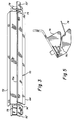
- the holder 70 has opposing portions 70a, 70b which are connected by appropriate fasteners to sandwich the blade 64 therebetween. Additionally, the holder 70 includes a portion extending along the length of the blade 64 in a direction away from the marginal edge of the blade (see Fig. 3).
- the portion 72 forms a catch tray for material removed from the web 12 by the blade.
- the holder 70 for the blade 64 is attached to the housing 66 for the cleaning brush 62 by being receivable in end brackets 74 fixed to the housing.
- the end brackets 74 respectively define a slot 76 (one bracket and slot shown in Fig. 5) for receiving tabs 70′ of the holder 70.
- spring members 78 (see Fig. 5) attached to the end brackets 74 engage the tabs and retain the holder 70 in fixed relation in the end brackets.
- the location of the end brackets 74 attached to the housing 66, the angle of the slots 76, and the dimensional configuration of the blade 64 and holder 70 assure the essential predetermined positional orientation of the blade relative to the web 12. As noted above, such predetermined positional orientation is essential to assure the effective operation of the cleaning blade 64.
- the blade 64 engages the web 12 at an angle to the normal path of travel of the web and under a force which, due to compliance of the web, substantially deflects the web from its normal path of travel (shown as a dashed line in Fig. 4).
- the angle at which the blade engages the web referred to the attack angle designated as angle A, is in the range of approximately 25°-30°.
- the loading of the blade 64 on the web 12 is in the range of approximately 12-30 gr/cm, which results in a deflection of the web in the range of approximately 0.25-0.600 cm from its undeflected location.
- the angle of deflection of the web designated as angle D, is in the range of approximately 1°-10°.
- the deflection of the web 12 by the blade 64 creates a substantially sharp discontinuity in the web as it travels past the blade. It is believed that material adhering to the web is shattered as the web travels through such discontinuity, rendering the material easier to clean from the web. Material cleaned by the blade 64 builds up in the catch tray 72.
- the blade and catch tray are within the effective range of the air flow created by the vacuum source V into the cleaning brush housing 66, at least a portion of the material building up on the blade and catch tray is entrained in the air flow so as to be cleaned away by the brush.
- the combined vacuum-assisted cleaning brush 62 and cleaning blade 64 of the cleaning assembly 60 are interdependent, each serving to enhance the operation of the other.
Landscapes
- Physics & Mathematics (AREA)
- General Physics & Mathematics (AREA)
- Cleaning In Electrography (AREA)
Claims (6)
- Elektrostatografisches Reproduktionsgerät (10) zur Bildung eines latenten Bildladungsmusters auf einem sich bewegenden bandförmigen dielektrischen Element (12), wobei das Ladungsmuster mit Pigmentpartikeln entwickelt wird, um ein Übertragungsbild zu erzeugen, mit einer Reinigungsvorrichtung (60) zum Entfernen von Restpartikeln und Verschmutzungen von dem Element (12), die
eine Reinigungsbürste (62) mit einer Umfangsfläche,
ein die Reinigungsbürste halterndes Gehäuse (66), das die Umfangsfläche der Reinigungsbürste in Berührungskontakt mit dem Element bringt,
eine Einrichtung (4) zum Erzeugen von Unterdruck innerhalb des Gehäuses und
eine relativ starr ausgebildete Reinigungsklinge (64) umfaßt,
gekennzeichnet durch eine Einrichtung (70), die die Reinigungsklinge in vorgegebener Lageausrichtung mit einer Kraft zwischen etwa 12 und 30 g/cm derart in Anlage mit dem Element hält, daß das Element (12) einer von der Reinigungsklinge (64) bewirkten, im wesentlichen in einem Bereich von etwa 2,5 bis 6 mm liegenden Auslenkung unterworfen wird. - Reinigungsvorrichtung nach Anspruch 1, dadurch gekennzeichnet, daß der Auslenkwinkel des Elements in einem Bereich zwischen etwa 1 und 10° liegt.
- Reinigungsvorrichtung nach Anspruch 1 oder 2, dadurch gekennzeichnet, daß die Einrichtung zum Haltern der Reinigungsklinge (64) derart angeordnet ist, daß sie die Klinge, in Bewegungsrichtung des Elements gesehen, hinter dem Gehäuse (66) positioniert.
- Reinigungsvorrichtung nach Anspruch 1 bis 3, dadurch gekennzeichnet, daß die Einrichtung zum Haltern der Reinigungsklinge (64) mit dem Gehäuse (66) derart verbunden ist, daß die Klinge, in Bewegungsrichtung des Elements gesehen, dem Berührungskontaktbereich zwischen Reinigungsbürste (62) und Element (12) benachbart angeordnet ist.
- Reinigungsvorrichtung nach Anspruch 4, dadurch gekennzeichnet, daß die Reinigungsklinge mittels der Halterungseinrichtung derart positioniert ist, daß sie sich im Wirkungsbereich des im Gehäuse herrschenden Unterdrucks befindet.
- Reinigungsvorrichtung nach Anspruch 1 bis 5, dadurch gekennzeichnet, daß die Reinigungsklinge einen Auffangbehälter (72) zum Sammeln der von ihr vom Element (12) abgeschabten Restpartikel und Verschmutzungen aufweist.
Applications Claiming Priority (3)
| Application Number | Priority Date | Filing Date | Title |
|---|---|---|---|
| US07/767,707 US5126798A (en) | 1991-09-30 | 1991-09-30 | Cleaning assembly for an electrostatographic reproduction apparatus |
| US767707 | 1991-09-30 | ||
| PCT/US1992/008111 WO1993007543A1 (en) | 1991-09-30 | 1992-09-24 | Cleaning assembly for an electrostatographic reproduction apparatus |
Publications (2)
| Publication Number | Publication Date |
|---|---|
| EP0559875A1 EP0559875A1 (de) | 1993-09-15 |
| EP0559875B1 true EP0559875B1 (de) | 1995-12-27 |
Family
ID=25080303
Family Applications (1)
| Application Number | Title | Priority Date | Filing Date |
|---|---|---|---|
| EP92921033A Expired - Lifetime EP0559875B1 (de) | 1991-09-30 | 1992-09-24 | Reinigungseinheit für elektrostatographisches bilderzeugungsgerät |
Country Status (5)
| Country | Link |
|---|---|
| US (1) | US5126798A (de) |
| EP (1) | EP0559875B1 (de) |
| JP (1) | JP3178838B2 (de) |
| DE (1) | DE69207172T2 (de) |
| WO (1) | WO1993007543A1 (de) |
Families Citing this family (8)
| Publication number | Priority date | Publication date | Assignee | Title |
|---|---|---|---|---|
| JP2827142B2 (ja) * | 1991-07-15 | 1998-11-18 | 株式会社リコー | 感光体クリーニング装置およびクリーナ・トナー・マガジンならびに画像形成装置 |
| US5339149A (en) * | 1993-08-23 | 1994-08-16 | Xerox Corporation | Non-stick spots blade |
| JP2691512B2 (ja) * | 1993-09-22 | 1997-12-17 | 株式会社リコー | 像保持体からの像形成物質除去方法及びその装置 |
| JP2000275983A (ja) | 1999-03-24 | 2000-10-06 | Toshiba Tec Corp | 転写装置、及びこの転写装置を備えた画像形成装置 |
| US6442367B1 (en) * | 1999-05-31 | 2002-08-27 | Konica Corporation | Electrophotographic image forming method, electrophotographic image forming apparatus, and processing cartridge |
| US6925282B2 (en) * | 2003-09-26 | 2005-08-02 | Xerox Corporation | Retractable agglomeration removable blade with cleaning mechanism and process for agglomeration removal |
| JP4807147B2 (ja) * | 2006-05-31 | 2011-11-02 | ブラザー工業株式会社 | 画像形成装置 |
| US8774697B2 (en) | 2011-07-29 | 2014-07-08 | Eastman Kodak Company | Electrophotographic printer and transitional cleaning system |
Family Cites Families (8)
| Publication number | Priority date | Publication date | Assignee | Title |
|---|---|---|---|---|
| JPS58114076A (ja) * | 1981-12-28 | 1983-07-07 | Ricoh Co Ltd | クリ−ニング装置 |
| US4435073A (en) * | 1982-08-16 | 1984-03-06 | Xerox Corporation | Toner removal apparatus |
| US4630920A (en) * | 1985-09-06 | 1986-12-23 | Xerox Corporation | Blade cleaning apparatus for removing residual toner from a charge retentive surface |
| JPH0625782B2 (ja) * | 1987-07-06 | 1994-04-06 | アンリツ株式会社 | 周波数判別回路 |
| EP0320812B1 (de) * | 1987-12-18 | 1993-09-15 | Fujitsu Limited | Reinigungseinheit zur Reinigung des Aufnahmematerials eines elektrophotographischen Gerätes |
| JPH01195488A (ja) * | 1987-12-22 | 1989-08-07 | Xerox Corp | 複写機のブレード清掃装置 |
| JPH0257890A (ja) * | 1988-08-19 | 1990-02-27 | Nkk Corp | 直流アーク炉炉底電極の冷却ファンの運転制御方法 |
| US4989047A (en) * | 1989-12-11 | 1991-01-29 | Xerox Corporation | Cleaning apparatus for the reduction of agglomeration-caused spotting |
-
1991
- 1991-09-30 US US07/767,707 patent/US5126798A/en not_active Expired - Lifetime
-
1992
- 1992-09-24 EP EP92921033A patent/EP0559875B1/de not_active Expired - Lifetime
- 1992-09-24 DE DE69207172T patent/DE69207172T2/de not_active Expired - Fee Related
- 1992-09-24 WO PCT/US1992/008111 patent/WO1993007543A1/en not_active Ceased
- 1992-09-24 JP JP50694993A patent/JP3178838B2/ja not_active Expired - Fee Related
Also Published As
| Publication number | Publication date |
|---|---|
| US5126798A (en) | 1992-06-30 |
| DE69207172T2 (de) | 1996-08-29 |
| JP3178838B2 (ja) | 2001-06-25 |
| JPH06503659A (ja) | 1994-04-21 |
| WO1993007543A1 (en) | 1993-04-15 |
| DE69207172D1 (de) | 1996-02-08 |
| EP0559875A1 (de) | 1993-09-15 |
Similar Documents
| Publication | Publication Date | Title |
|---|---|---|
| US5028959A (en) | Vacuum collection system for dirt management | |
| EP0366426B1 (de) | Elektrophotographische Vorrichtung mit einer mittels Wechselspannung betriebenen Reinigungseinrichtung | |
| EP0432453B1 (de) | Reinigungsgerät für die Reduktion von Fleckbildungen, die durch Toneragglomerat verursacht werden | |
| EP0103405B1 (de) | Gerät zur Entfernung von Toner | |
| EP0521131B1 (de) | Übertragungstrommelmontage | |
| US4121947A (en) | Method of cleaning a photoreceptor | |
| EP0404491A2 (de) | Elektrostatisches Bilderzeugungsgerät | |
| US4697914A (en) | Toner containment method and apparatus | |
| US5444522A (en) | Replaceable cleaner subsystem that prevents particle spillage | |
| US5126798A (en) | Cleaning assembly for an electrostatographic reproduction apparatus | |
| US4038546A (en) | Cleaning apparatus for a corona generating device | |
| US5329344A (en) | Lubrication of a detoning roll | |
| JP3231486B2 (ja) | クリーニング装置 | |
| EP0346454B1 (de) | Reinigungseinrichtung für doppelte zwecke | |
| JPH10301409A (ja) | 転写ローラ電気的バイアス制御 | |
| US5479249A (en) | Brush cleaner with roll detoning and air waste removal | |
| US4029047A (en) | Toner handling system | |
| EP0276581A1 (de) | Verfahren und Vorrichtung zum Entfernen des Toners von einer fotoleitenden Trommel in einem xerographischen Gerät | |
| US5315358A (en) | Flicker bar with an integral air channel | |
| US3404418A (en) | Sheet transport apparatus | |
| US6169872B1 (en) | Electrostatic cleaning belt brush | |
| US5381218A (en) | Conductive cleaning brush belt and detoning thereof | |
| US5239350A (en) | Cleaning system failure detector | |
| EP0620508B1 (de) | Reinigungsvorrichtung | |
| US5491544A (en) | Mounting mechanism for a roller transfer assembly |
Legal Events
| Date | Code | Title | Description |
|---|---|---|---|
| PUAI | Public reference made under article 153(3) epc to a published international application that has entered the european phase |
Free format text: ORIGINAL CODE: 0009012 |
|
| AK | Designated contracting states |
Kind code of ref document: A1 Designated state(s): DE FR GB |
|
| 17P | Request for examination filed |
Effective date: 19930918 |
|
| 17Q | First examination report despatched |
Effective date: 19941110 |
|
| GRAA | (expected) grant |
Free format text: ORIGINAL CODE: 0009210 |
|
| AK | Designated contracting states |
Kind code of ref document: B1 Designated state(s): DE FR GB |
|
| REF | Corresponds to: |
Ref document number: 69207172 Country of ref document: DE Date of ref document: 19960208 |
|
| ET | Fr: translation filed | ||
| PLBE | No opposition filed within time limit |
Free format text: ORIGINAL CODE: 0009261 |
|
| STAA | Information on the status of an ep patent application or granted ep patent |
Free format text: STATUS: NO OPPOSITION FILED WITHIN TIME LIMIT |
|
| 26N | No opposition filed | ||
| REG | Reference to a national code |
Ref country code: GB Ref legal event code: 732E |
|
| REG | Reference to a national code |
Ref country code: GB Ref legal event code: IF02 |
|
| REG | Reference to a national code |
Ref country code: GB Ref legal event code: 732E |
|
| PGFP | Annual fee paid to national office [announced via postgrant information from national office to epo] |
Ref country code: GB Payment date: 20050809 Year of fee payment: 14 |
|
| PGFP | Annual fee paid to national office [announced via postgrant information from national office to epo] |
Ref country code: FR Payment date: 20050902 Year of fee payment: 14 |
|
| PGFP | Annual fee paid to national office [announced via postgrant information from national office to epo] |
Ref country code: DE Payment date: 20050930 Year of fee payment: 14 |
|
| PG25 | Lapsed in a contracting state [announced via postgrant information from national office to epo] |
Ref country code: DE Free format text: LAPSE BECAUSE OF NON-PAYMENT OF DUE FEES Effective date: 20070403 |
|
| GBPC | Gb: european patent ceased through non-payment of renewal fee |
Effective date: 20060924 |
|
| REG | Reference to a national code |
Ref country code: FR Ref legal event code: ST Effective date: 20070531 |
|
| PG25 | Lapsed in a contracting state [announced via postgrant information from national office to epo] |
Ref country code: GB Free format text: LAPSE BECAUSE OF NON-PAYMENT OF DUE FEES Effective date: 20060924 |
|
| PG25 | Lapsed in a contracting state [announced via postgrant information from national office to epo] |
Ref country code: FR Free format text: LAPSE BECAUSE OF NON-PAYMENT OF DUE FEES Effective date: 20061002 |