EP0560331B1 - Dispositif et procédé de positionnement d'une partie du corps pour le traitement thérapeutique - Google Patents
Dispositif et procédé de positionnement d'une partie du corps pour le traitement thérapeutique Download PDFInfo
- Publication number
- EP0560331B1 EP0560331B1 EP93103855A EP93103855A EP0560331B1 EP 0560331 B1 EP0560331 B1 EP 0560331B1 EP 93103855 A EP93103855 A EP 93103855A EP 93103855 A EP93103855 A EP 93103855A EP 0560331 B1 EP0560331 B1 EP 0560331B1
- Authority
- EP
- European Patent Office
- Prior art keywords
- markings
- body part
- sensors
- patient
- head
- Prior art date
- Legal status (The legal status is an assumption and is not a legal conclusion. Google has not performed a legal analysis and makes no representation as to the accuracy of the status listed.)
- Expired - Lifetime
Links
Images


Classifications
-
- A—HUMAN NECESSITIES
- A61—MEDICAL OR VETERINARY SCIENCE; HYGIENE
- A61B—DIAGNOSIS; SURGERY; IDENTIFICATION
- A61B6/00—Apparatus or devices for radiation diagnosis; Apparatus or devices for radiation diagnosis combined with radiation therapy equipment
- A61B6/08—Auxiliary means for directing the radiation beam to a particular spot, e.g. using light beams
-
- A—HUMAN NECESSITIES
- A61—MEDICAL OR VETERINARY SCIENCE; HYGIENE
- A61N—ELECTROTHERAPY; MAGNETOTHERAPY; RADIATION THERAPY; ULTRASOUND THERAPY
- A61N5/00—Radiation therapy
- A61N5/10—X-ray therapy; Gamma-ray therapy; Particle-irradiation therapy
- A61N5/1048—Monitoring, verifying, controlling systems and methods
- A61N5/1049—Monitoring, verifying, controlling systems and methods for verifying the position of the patient with respect to the radiation beam
-
- G—PHYSICS
- G05—CONTROLLING; REGULATING
- G05B—CONTROL OR REGULATING SYSTEMS IN GENERAL; FUNCTIONAL ELEMENTS OF SUCH SYSTEMS; MONITORING OR TESTING ARRANGEMENTS FOR SUCH SYSTEMS OR ELEMENTS
- G05B19/00—Program-control systems
- G05B19/02—Program-control systems electric
- G05B19/18—Numerical control [NC], i.e. automatically operating machines, in particular machine tools, e.g. in a manufacturing environment, so as to execute positioning, movement or co-ordinated operations by means of program data in numerical form
- G05B19/408—Numerical control [NC], i.e. automatically operating machines, in particular machine tools, e.g. in a manufacturing environment, so as to execute positioning, movement or co-ordinated operations by means of program data in numerical form characterised by data handling or data format, e.g. reading, buffering or conversion of data
- G05B19/4086—Coordinate conversions; Other special calculations
-
- A—HUMAN NECESSITIES
- A61—MEDICAL OR VETERINARY SCIENCE; HYGIENE
- A61B—DIAGNOSIS; SURGERY; IDENTIFICATION
- A61B90/00—Instruments, implements or accessories specially adapted for surgery or diagnosis and not covered by any of the groups A61B1/00 - A61B50/00, e.g. for luxation treatment or for protecting wound edges
- A61B90/10—Instruments, implements or accessories specially adapted for surgery or diagnosis and not covered by any of the groups A61B1/00 - A61B50/00, e.g. for luxation treatment or for protecting wound edges for stereotaxic surgery, e.g. frame-based stereotaxis
- A61B2090/101—Instruments, implements or accessories specially adapted for surgery or diagnosis and not covered by any of the groups A61B1/00 - A61B50/00, e.g. for luxation treatment or for protecting wound edges for stereotaxic surgery, e.g. frame-based stereotaxis for stereotaxic radiosurgery
-
- A—HUMAN NECESSITIES
- A61—MEDICAL OR VETERINARY SCIENCE; HYGIENE
- A61B—DIAGNOSIS; SURGERY; IDENTIFICATION
- A61B90/00—Instruments, implements or accessories specially adapted for surgery or diagnosis and not covered by any of the groups A61B1/00 - A61B50/00, e.g. for luxation treatment or for protecting wound edges
- A61B90/36—Image-producing devices or illumination devices not otherwise provided for
- A61B2090/363—Use of fiducial points
-
- A—HUMAN NECESSITIES
- A61—MEDICAL OR VETERINARY SCIENCE; HYGIENE
- A61B—DIAGNOSIS; SURGERY; IDENTIFICATION
- A61B90/00—Instruments, implements or accessories specially adapted for surgery or diagnosis and not covered by any of the groups A61B1/00 - A61B50/00, e.g. for luxation treatment or for protecting wound edges
- A61B90/36—Image-producing devices or illumination devices not otherwise provided for
- A61B90/37—Surgical systems with images on a monitor during operation
- A61B2090/371—Surgical systems with images on a monitor during operation with simultaneous use of two cameras
-
- A—HUMAN NECESSITIES
- A61—MEDICAL OR VETERINARY SCIENCE; HYGIENE
- A61B—DIAGNOSIS; SURGERY; IDENTIFICATION
- A61B90/00—Instruments, implements or accessories specially adapted for surgery or diagnosis and not covered by any of the groups A61B1/00 - A61B50/00, e.g. for luxation treatment or for protecting wound edges
- A61B90/36—Image-producing devices or illumination devices not otherwise provided for
- A61B90/37—Surgical systems with images on a monitor during operation
- A61B2090/373—Surgical systems with images on a monitor during operation using light, e.g. by using optical scanners
-
- A—HUMAN NECESSITIES
- A61—MEDICAL OR VETERINARY SCIENCE; HYGIENE
- A61B—DIAGNOSIS; SURGERY; IDENTIFICATION
- A61B90/00—Instruments, implements or accessories specially adapted for surgery or diagnosis and not covered by any of the groups A61B1/00 - A61B50/00, e.g. for luxation treatment or for protecting wound edges
- A61B90/39—Markers, e.g. radio-opaque or breast lesions markers
-
- A—HUMAN NECESSITIES
- A61—MEDICAL OR VETERINARY SCIENCE; HYGIENE
- A61N—ELECTROTHERAPY; MAGNETOTHERAPY; RADIATION THERAPY; ULTRASOUND THERAPY
- A61N5/00—Radiation therapy
- A61N5/10—X-ray therapy; Gamma-ray therapy; Particle-irradiation therapy
- A61N5/1048—Monitoring, verifying, controlling systems and methods
- A61N5/1049—Monitoring, verifying, controlling systems and methods for verifying the position of the patient with respect to the radiation beam
- A61N2005/1059—Monitoring, verifying, controlling systems and methods for verifying the position of the patient with respect to the radiation beam using cameras imaging the patient
Definitions
- Such a device is disclosed by US-A-3,861,807 known.
- a small reflector attached to the skin of the body part to be treated.
- a light source is directed to the body part.
- the Light source produces concentric rings with different Intensity.
- the intensity of the reflector reflected light is transmitted through a photoelectric cell measured. When the reflector is in the middle of the light beam the intensity is highest.
- the too treating body part is dependent on by moving the photoelectric cell's measured intensity so that the place to be treated with respect to the medical Device is always in the same location. This will the body part positioned so that a well-defined Treatment point is held in a desired position. It can also use light sources and reflectors in pairs to be available.
- the invention relates to the irradiation of tumors in the brain by means of an irradiation device.
- the beam of the irradiation device should be reduced to fractions One millimeter hit the tumor exactly. This counteracts damage to healthy tissue and optimally exploited the radiation. It has proved to be advantageous in such irradiation Do not use the entire dose at once bring. Rather, should have a number of smaller doses be applied at intervals. Farther The radiation doses should advantageously be off be irradiated in different directions. Thereby the radiation spreads, which also affects the surrounding, healthy tissue strikes a larger area. The Danger of irreparable damage to healthy tissue is therefore diminished.
- the rays coming from the irradiation device go out in the application of the different doses exactly in an isocenter in the area of the tumor to be irradiated. But that is advance that the patient's head with appropriate Precision reproducibly positioned and aligned becomes.
- the tumor (treatment point), whose location is determined then becomes accurate through an optical alignment system aligned to the isocenter through which the beam of the Irradiation unit always goes through.
- EP-A-0 114 505 discloses a method or a method Device for calibrating a robot, wherein the Calibration means Facilities for determining the position a robotic arm included when the arm is a Workstation reached. For this purpose is a Target with multiple markings on the robot arm appropriate. The. Target is not with the Robot arm connected cameras from different Angles observed. In a computer, this is the Actual position of the robot arm calculated. The actual position is compared with the target position and a calibration performs.
- US-A-4,705,955 forms a technological Background. There is a table shown on the one Patient should be, who is irradiated and being small Movements of the patient with respect to the table during the actual irradiation should be determined and the position of the table will be corrected accordingly should.
- US-A-4,396,945 shows a device in which the Location of an element in space, for example one Robot arm or another platform, right through electro-optical means can be detected.
- the invention is based on the object, a body part a patient for treatment purposes in a well-defined and reproducible position relative to one Device to hold.
- the invention is based on the object, the Head of the patient in a fractionated irradiation with an irradiation device in successive treatments in a well-defined position relative to that To hold the beam of the irradiation device.
- the position of the head or other body part by scanning the mark determined by means of the sensors. Through a loop is maintain the right position. It has surprisingly shown that in this way a higher Accuracy of positioning is achievable as by mechanical fixation. Instead of a tracking of the head to align the treatment point with the isocenter can also be done a deflection of the beam. In case of emergancy Can the device in a misalignment device be switched off.
- the sensor contains means for generating a pixel matrix, in which the markings as flat structures appear.
- the image processing means are for Determination of the centers of gravity of the surface area obtained in this way Structures designed as marker points.
- the resolution usual sensors of this kind is lower than the required positioning accuracy. But if you have the Focus of one of these sensors detected areal Forming structure with conventional means of pattern recognition, so in a sense averaging over the relatively coarse grid, then this focus is with the required accuracy Are defined. It can do so by scanning the relatively extensive marks sub-pixel accurate "Marker points" are determined. These set the actual position of the body to be treated partly with sufficient Accuracy.
- the markings can be formed by balls that are in the pixel matrix independent of the direction of observation as circular structures appear. To simplify the Image processing, it is useful if the balls are deposited by contrasting surfaces. It can be one Lighting device for illuminating the balls of be provided on several pages.
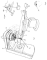
- the device For precise positioning of the head of a patient relative to an irradiation device, wherein the Treatment point lies in a tumor to be irradiated, the device contains an irradiation table and a on the irradiation table in the horizontal longitudinal direction sliding carriage, on which the patient at Use of the device is located, and one of the Radiation table separate head rest, on which at Use of the device the head of the patient detectable rests.
- a first and a second of the said Actuators grip vertically and horizontally Transverse direction at the head rest on for movement the same relative to the irradiation table.
- a third Actuator engages in the horizontal longitudinal direction of the Carriage to the longitudinal displacement of the carriage.
- Fig.1 is schematically an irradiation device for Irradiation of a brain tumor presented.
- the irradiation device is designated 10. It creates one Beam 12 of high-energy gamma secondary radiation.
- the Cross section of the beam 12 is determined by a diaphragm 14.
- a patient lies on an irradiation table 16.
- the irradiation device 10 To move a tumor sequentially from different directions to be able to irradiate and thus the burden of the To minimize beam-penetrated healthy tissue is the irradiation device 10 about an axis 18th pivotable.
- the beam 12 cuts the axis 18 in an isocenter 20 Setting the irradiation table in this isocenter to be brought. If that is the case, then it goes Beam even with a tilt of the irradiation device 10 about the axis 18 always through the tumor, such as is indicated in Fig.2.
- the exact position of the to be irradiated Tumor determined in the skull of the patient. This is a known and therefore not shown here technology.
- a ring is attached to the skull of the patient.
- To the Ring are attached to acrylic glass body with metal wires.
- the metal wires serve as markings.
- the patient's head with this ring will be a computed tomogram or created a nuclear spin tomogram, which to detect the location of the tumor and the metal wires.
- the location of the tumor is then in one through the Given metal wires defined coordinate system.
- the one to be irradiated becomes Body part by stereotactic method exactly aligned and fixed. Then there is the Treatment point, so about a tumor, exactly in the isocenter of the device.
- the isocenter is a defined point in the device-fixed coordinate system.
- the markings may also be as claimed in claim 10, on one of the teeth attached to the patient adapted mouthpiece. These markings are generated by means of image signal generating Sensors 34, 36 on the type of video cameras in the observed above described first alignment. This determines the starting position. At later Irradiations become the markers of the spacers held sensors 34, 36 detected. From the picture information the sensors are determined an actual position. Through a control circuit with servomotors of the skull the patient moves back to the desired position.
- FIG. 3 shows an example of such markings.
- the markings are of bright balls formed, standing against a dark background are located.
- the marks 22, 24, 26 and 28 are generated by two image signal generating Sensors 34 and 36 observed.
- Lamps 38 and 40 are as even as possible Illumination of the markings from all sides.
- the two sensors are in one vertical plane at a horizontal distance of about 500 mm and about 600 mm above the mark 30 containing horizontal plane arranged. You are with their optical axes 44 and 46 substantially on the Focus 30 aligned. This focus is 30 at a distance of about 500 mm from the sensors 34 and 36 contained vertical plane in the to this Vertical plane vertical, vertical plane of symmetry between the sensors 34 and 36.
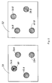
- the sensors 34 and 36 provide a pixel matrix 50 and 52. Each pixel of the sensor 34 or 36 captured image provides a brightness value.
- Fig.5 shows an example of the sensors 34 and 36 supplied pixel matrices 50 and 52, respectively the pixel matrices 50 and 52 have circular formations 54A, 56A, 58A, 60A and 54B, 56B, 58B, 60B as images of the Marks 22, 24, 26, 28.
- the markings are bullets. As images therefore arise independently of the Observation direction essentially circles.
- the image processing now includes the following steps:
- the pixels represent a relatively coarse grid Dimensions of a pixel projected into the plane of the Markings are larger than the required positioning accuracy. Of course, the dimensions of the Markings themselves much larger than the required Positioning accuracy.
- the next step is therefore in a specialization. It will be the focal points the objects identified as images of the markers educated. The coordinates of the focal points can with much greater accuracy than a pixel length or height are determined.
- the center of gravity is shown in Fig.4 by blocks 74 and 76th indicated.
- Points 80 defines the focal points of the images correspond to the markings. From the points 80 and the Figure characteristics of the optics of the sensor 34 or 36 (including aberrations) of the beam 48 calculated from the sensor 34 or 36 to the Center of gravity of the marker (e.g., 22).
- the location and the orientation of all Sensors in the coordinate system of the irradiation device in small time intervals can be accurately determined.
- a reference body with its center in the Isocenter 20 brought.
- the marked axes of the Reference bodies are parallel to the axes of the on the Irradiation device 10 related, spatially fixed coordinate system aligned.
- the reference body carries five Marks. These marks are also from bullets formed in front of a contrasting background.
- the location the markings to the center of the reference body is known exactly. It then becomes the location of the sensor with three Cartesian coordinates and three attitude angles with respect to the coordinate system of the reference body from the Focal points of the pictured markings calculated.
- the one to be irradiated becomes Body part by means of stereotactic methods, such as described, aligned and fixed. Then it is the treatment point (tumor) exactly in the isocenter 20. In This position will be the positions of the body part attached markers by means of the sensors 34 and 36th determined in the device-fixed coordinate system as follows:
- the positional deviation from the Target position from the current center of gravity coordinates of calculated markers is due to a shift with three translation sizes and described a rotation with three rotation angles.
- the calculation uses again as in the measurement of Sensors the inverse function: It will be the focal points the images of the markers 22, 24, 26, 28 in the image coordinate systems the sensors 34 and 36 as a function calculated the six degrees of freedom of the position deviation.
- the coordinates of the four marks provide the actual position a "patient-fixed" coordinate system. These Actual position is compared with the "target position", the determined at the first exact positioning and in a memory 92 has been stored. A controller 94 determined the deviation of actual position and nominal position and generates control signals at outputs 98. The Control signals are applied to actuators, which are symbolized by block 104 in Figure 4.
- FIG. 6 schematically shows a sensor, for example 34.
- the image-forming sensor 34 is in the form of a camera a camera body 110 and a lens 112.
- the lens 112 forms a planar test object 114 on a two-dimensional Arrangement 116 from sensor elements.
- the test object contains a pattern, e.g. a pattern of concentric Circles with a center 118.
- the test object 114 is arranged to the sensor 34 so that the central axis 120 of the sensor 34 substantially through the center 118 goes. It creates a corresponding pattern the two-dimensional array 116 of sensor elements.
- the image is slightly distorted. This is exaggerated in Fig. 7. Due to alignment errors, the center 118 may not lie exactly in the middle of the arrangement 116 of sensor elements. The center 118 is mapped to a foot 122. At this base point 122, the image of the pattern detected by the arrangement 116 of sensor elements is acquired. It is assumed that the distortion of the objective 112 is rotationally symmetrical, that is, it depends only on the radius related to the base 122. . In the case of ideal imaging, the characteristic of Figure 7 would be a less than 45 ° to the r gem - and r is to coordinate axes extending straight line 124.
- the measured radius r gem is slightly smaller than it should be for an ideal map.
- a point 128 of the pattern is imaged by the objective 112 at point 130 on the array 116 of sensor elements, rather than at the point 132 resulting from the line 136 passing through the main point 134 of the objective 112.
- the point 130 would be associated with the beam 138 at a point 140.
- sk y or sk z can be further considered the ratio of beam angle to pixel coordinates. There is one such factor for each coordinate direction. This then results in a representation that faithfully reflects the position of the points in the object plane. In the same way, the sensor 36 is moved.
- the coefficients a 3 and a 5 and the aforementioned factor represent "inner camera parameters" for the two sensors 34 and 36. They are determined once and entered into the computer for signal processing. It can thus be assigned to each sensor element a corresponding line of sight.
- the next step is the initialization of the position, ie the position and orientation of the two sensors 34 and 36.
- Position and orientation of the sensors 34 and 36 are measured in a coordinate system which is fixedly aligned with the irradiation device 10. Conveniently, the origin of the coordinate system is placed in the isocenter 20.
- a coordinate axis x I is aligned with the pivot axis 18 of the irradiation device, a coordinate axis z I is vertical, and the third coordinate axis y I is perpendicular to the coordinate axes x I and z I. This is shown in Fig. 1.
- FIG. 8 shows the coordinate system x I , y I and z I.
- a reference body 144 is arranged such that it is fully detected by the sensors 34 and 36.
- the reference body 144 has five marks 145, 146, 148, 150 and 152.
- the markers 145, 146, 148, 150 and 152 are similar to the markings 22 to 28 formed by balls, which are seen by the sensors 34 and 36, regardless of the direction of observation as circular structures.
- the position of the reference body 144 and the positions of the markers 145 to 152 in the coordinate system x I , y I , z I are well known. These positions of the marks are entered into the computer.
- Each of the sensors 34 and 36 now provides an image in the five marks 145 to 152 as a circular Structures appear.
- the three rotations can be described by three transformation matrices or direction cosine matrices R z ( ⁇ ), R y ( ⁇ ) and R x ( ⁇ ).
- R Z ( ⁇ m ) cos ⁇ m sin ⁇ m 0 -sin ⁇ m cos ⁇ m 0 0 0 1
- R Y ( ⁇ m ) cos m 0 -sin ⁇ m 0 1 0 sin ⁇ m 0 cos m
- R X ( ⁇ m ) 1 0 0 0 cos m sin ⁇ m 0 - sin ⁇ m cos m
- the sensor coordinate system for example of the sensor 36, can be defined by three unit vectors E x2, E y2, E z2 in the direction of the three coordinate axes x s2, y s2, x s2 .
- e S Y2 0 1 0 .
- e S Z2 0 0 1
- the position vector of the center of the ith mark 145 to 152 should be designated in the stationary coordinate system. This location vector is well known.
- the matrix R with the angle functions of the Euler angle is estimated, so not exactly known, and then of course also applies for the unit vectors E I / xm, E I / ym, EI / zm with respect to the fixed coordinate system x I, y I, z I. It is calculated which coordinates would have the centers of the images of the markers 145 to 152 assuming such a position of the sensors 34 and 36 in the sensor-oriented coordinate systems.
- the vector difference M i - S m is the vector of the principal point 134 of the lens 112 to a mark "i" of the reference body 144.
- the scalar multiplication of the vector difference with the unit vector in the y s direction provides the component of this vector difference in y s direction
- the scalar multiplication of the vector difference M i - S m with the unit vector E S / xm supplies the component of the vector difference in the optical axis direction 120 of the sensor 34 or 36.
- the ratio of the scalar products is approximately the angle that the vector difference optical with the Axis 120 of the sensor 34 or 36 forms. Multiplied by the factor sk y results in the y s coordinate y i of the calculated from the estimated position of the sensor 34 or 36 pixel.
- coordinates y i corr and z i corr are observed. These are the coordinates of the sensor elements corresponding to the centers of the images of the marks 145 to 152, corrected - as explained above - with regard to the internal camera parameters.
- the assumed position (position S m and orientation R m ) of the sensor 34 or 36 generally does not initially correspond to the true position.
- the named error vectors occur.
- the searched vector v has six components.
- the error vectors provide a total of ten errors. It is now necessary to vary the components of the vector v , ie for the sensor 36, the coordinates x I2, y I2, z I2 and the Euler angles ⁇ , ⁇ , ⁇ in such a way that the errors disappear. This can be done by means of the well-known Newtonian iteration.
- grad F 0 , where 0 is the zero vector.
- v (N + 1) v (N) - (D. T D) -1 D T f
- v (n + 1) and v (n) are the approximations for the vector v resulting from the (n + 1) th or n-th iteration step.
- D T is the transposed Jacobian matrix D, ie a matrix in which lines and columns are interchanged with respect to the matrix D.
- the character -1 means the inverse matrix.
- f (n) is the error vector after the nth iteration step.
- the obtained data on the position of the sensors 34 and 36th are saved. These data are then for used the positioning of patients.
- the determination the position of the sensors is measured at regular intervals, e.g. daily, repeatedly.
- the absolute position in space in the fixed coordinate system x I, y I, z I is independently determined.
- a starting value is first determined as the "intersection point" of the visual rays directed by the two sensors 34 and 36 on one and the same marking. Due to measurement inaccuracies, the visual rays in space generally do not have an exact intersection. Therefore, the center of the distance between the visual rays is selected as the "intersection point".
- the exact position of the markers 22, 24, 26 and 28 in the stationary coordinate system x I, y I, z I for each mark is determined individually again by means of a Newton iteration starting from the starting values.
- the observed and corrected with respect to the inner camera parameters coordinates of Images of marks 145 to 152 in the sensor-oriented coordinate system Similar to the measurement of the position of the sensors 34 and 36 by means of the test body 144 - S 1 and S 2 position vectors of the sensors 34 and 36 and y mkorr and Z mkorr the observed and corrected with respect to the inner camera parameters coordinates of Images of marks 145 to 152 in the sensor-oriented coordinate system.
- the errors are again known functions of the estimated position coordinates x j , y j and z j (P 1 , P 2 , P 3 ).
- There can then be a Jacobi matrix D * with the elements D * ik ⁇ f
- a "self-coordinate system" x E, y E, z E is defined.
- the origin of this self-coordinate system lies in the centroid 30 of the four markers 22, 24, 26 and 28.
- the unit vector pointing in z E direction is the normalized vector product of the two vectors 154 and 156, which are the centroids of the markers 24 and 26 and 28 and 22 connect together (Fig. 9).
- This unit vector and the z E -axis are thus perpendicular to the paper plane of Fig. 9 and are directed into this plane of the paper.
- the unit vector pointing in the direction of the y E axis runs parallel to the connecting line 158 between the centers of gravity of the markings 22 and 28.
- the y E axis points to the left in FIG. 9.
- the unit vector pointing in the direction of the x E axis forms with the unit vectors of the y E and z E axes, a legal system and points down in FIG. 9.
- the data P j thus obtained are stored. If the markers 22, 24, 26 and 28 are in this position, then the tumor is exactly in the isocenter 20.
- a vector k ( ⁇ X k , ⁇ Y k , ⁇ Z k , ⁇ k , ⁇ k , ⁇ k ) searched.
- Components of this vector are the deviations of the position of the head-fixed, determined by the markers 22, 24, 26 and 28 self-coordinate system of the situation, which was determined and stored in the manner described above and in which the head of the patient as determined by stereotactic methods Location with the tumor was kept in the isocenter 20.
- f i y2 sk y2 ⁇ e I Y2 (R k ⁇ P i + t ) - S 2 ) e I X2 (R k P i + t ) - S 2 ) - Y i 2 corr
- f i z2 sk z2 ⁇ e I Z2 (R k P i + t ) - S 2 ) e I X2 (R k P i + t ) - S 2 ) - Z i 2 corr
- the ratios provide angles which, with a scale factor sk ym and sk zm, respectively, provide the calculated coordinates of the images of the markers 22, 24, 26 or 28 on the array 116 of sensor elements in the most sensor-coarse coordinate system.
- the difference to the actual observed images (with correction for the internal camera parameters) provide the errors.
- the sixteen components of the error vector f are known functions of the six components of the vector k . It is again possible to form a Jacobi matrix D 'from the partial derivatives of the components of the error vector f for each component of the vector k .
- Such a Jacobi matrix is a 16x6 matrix.
- Estimates for the positions of the markers 22, 24, 26 and 28 are first determined as the intersection of two visual rays to carry out the Newtonian iteration.
- the origin and coordinate directions of the eigen coordinate system x E, y E, z E of the markings 22, 24, 26 and 28 result from these estimated values.
- Rotation and translation of the change in position are determined from this actual coordinate system and the stored eigen coordinate system determined in the original position determines, that is, the mapping, which maps the eigen coordinate system of the initial position to the current self-coordinate system. This provides as starting values components of the vector k .
- the actual components of the vector k are then calculated on the basis of the starting values of the vector k by means of the above-described Newtonian iteration.
- Fig.1 is the Patient on a sledge 15 in horizontal Longitudinally slidable on a radiation table 16 is guided.
- the patient's head lies on one Headrest 108.
- the headrest 108 is relative to the Carriage movable in vertical and in transverse direction. In Transverse direction is the headrest 108 by an actuator 160 adjustable. In vertical direction is the headrest 108 adjustable by an actuator 162.
- An adjustment the headrest 108 in the longitudinal direction relative to the Sled 15 or radiation table 16 is not provided, since then the neck of the patient at a Adjustment would have to be stretched or compressed. Instead takes place in the longitudinal direction an adjustment of Slide 15 by an actuator 164.
- the head of the Patients may use conventional means on the headrest 108 be fixed. Any movements are but through the control circuits out-regulated.
- the "tumor point" in the head of the patient remains in the isocenter with high accuracy 20th
- the described arrangement can in various ways be modified. Instead of two sensors 34 and 36 can three sensors are provided. With over-determination can then the coordinates from the calculated rays 44,46 .. calculated according to the least squares method become.
Landscapes
- Health & Medical Sciences (AREA)
- Engineering & Computer Science (AREA)
- Life Sciences & Earth Sciences (AREA)
- Biomedical Technology (AREA)
- Medical Informatics (AREA)
- Public Health (AREA)
- Physics & Mathematics (AREA)
- Nuclear Medicine, Radiotherapy & Molecular Imaging (AREA)
- General Health & Medical Sciences (AREA)
- Pathology (AREA)
- Radiology & Medical Imaging (AREA)
- Veterinary Medicine (AREA)
- Animal Behavior & Ethology (AREA)
- Surgery (AREA)
- Manufacturing & Machinery (AREA)
- Heart & Thoracic Surgery (AREA)
- Optics & Photonics (AREA)
- High Energy & Nuclear Physics (AREA)
- Biophysics (AREA)
- Human Computer Interaction (AREA)
- Molecular Biology (AREA)
- General Physics & Mathematics (AREA)
- Automation & Control Theory (AREA)
- Radiation-Therapy Devices (AREA)
- Image Processing (AREA)
- Apparatus For Radiation Diagnosis (AREA)
- Apparatuses And Processes For Manufacturing Resistors (AREA)
- Control Of Position Or Direction (AREA)
Claims (12)
- Dispositif de positionnement d'une partie du corps en vue de son traitement avec un appareil médical (10), comprenant:(a) des moyens (22, 24, 26, 28, 38, 40) générant des informations optiques sur la position de la partie du corps par rapport à l'appareil médical (10),(b) au moins deux capteurs (34, 36) générant des signaux visuels, orientés en vue de l'observation des informations optiques,(c) des moyens de traitement d'images (74, 76) traitant les signaux visuels (54A, 56A, 58A, 60A, 54B, 56B, 58B, 60B) des capteurs (34, 36), générés au départ des informations optiques,(d) des moyens de traitement et de régulation des signaux (90, 92, 94)pour déterminer la position réelle de la partie du corps à partir des informations optiques observées,pour comparer la position réelle à une position de consigne etpour générer des signaux de réglage qui sont tributaires de l'écart-type entre la position réelle et la position de consigne, et(e) des moyens (104; 160, 162, 164) qui sont sous l'influence des signaux de réglage, pour positionner la partie du corps, de façon à ce qu'un point de traitement rigoureusement défini soit maintenu dans une position de consigne, et pour éviter un traitement si l'orientation de l'appareil (10) par rapport à la partie du corps est mauvaise,
caractérisé en ce que:(f) les moyens (22, 24, 26, 28, 38, 40) générant des informations optiques sur la position de la partie du corps par rapport à l'appareil médical (10) comportent au moins deux repères (22, 24, 26, 28) qui sont adaptés pour être placés en des emplacements définis sur la partie du corps,(g) les capteurs (34, 36) générant des signaux visuels comprennent des moyens générant une matrice de pixels (50, 52) dans laquelle les repères (22, 24, 26, 28) apparaissent sous forme de structures bidimensionnelles (54A, 56A, 58A, 60A, 54B, 56B, 58B, 60B),(h) les moyens de traitement d'images (74, 76) déterminant les barycentres (80) des structures bidimensionnelles sont conçus sous forme de points de repère qui sont déterminés par les repères (22, 24, 26, 28) et définissent la position réelle de la partie du corps, et(i) les moyens de traitement et de régulation de signaux (90, 92, 94) coopèrent de telle sorte que la détermination de la position réelle de la partie du corps à partir des informations optiques observées se fait par calcul. - Dispositif selon la revendication 1, caractérisé en ce que les moyens (104; 160, 162, 164) empêchant un traitement en cas de mauvaise orientation comprennent des servo-positionneurs qui sont sous l'influence des signaux de réglage et permettent un rétablissement de l'orientation de l'appareil (10) par rapport à la partie du corps si la partie du corps s'écarte de la position de consigne.
- Dispositif selon la revendication 2, caractérisé en ce que les servo-positionneurs (104; 160, 162, 164) sont adaptés pour intervenir sur la partie du corps de telle façon que dans le cas d'un écartement par rapport à la position de consigne, la partie du corps puisse être replacée dans la position de consigne par les servo-positionneurs (104; 160, 162, 164)
- Dispositif selon l'une quelconque des revendications 1 à 3, caractérisé en ce que les repères (22, 24, 26, 28, 30) sont constitués par des sphères qui apparaissent dans la matrice de pixels (50, 52), indépendamment de la direction d'observation, sous forme de structures circulaires (54A, 56A, 58A, 60A, 54B, 56B, 58B, 60B).
- Dispositif selon la revendication 4, caractérisé en ce que les sphères sont doublées de surfaces contrastees.
- Dispositif selon la revendication 4 ou 5, caractérisé en ce qu'un dispositif d'éclairage (38, 40) a été prévu afin d'éclairer les sphères de plusieurs côtés.
- Dispositif selon l'une quelconque des revendications 1 à 6, caractérisé en ce qu'au moins trois repères (22, 24, 26, 28) ont été prévus.
- Dispositif selon l'une quelconque des revendications 1 à 7, pour le positionnement précis de la tête d'un patient par rapport à un dispositif d'irradiation (10), le point de traitement se trouvant dans une tumeur qu'il s'agit d'irradier,
caractérisé par:(a) une table d'irradiation (16) et un chariot (15) coulissant dans le sens longitudinal horizontal sur la table d'irradiation, destiné à accueillir le patient,(b) un support pour tête (108) séparé de la table d'irradiation (16) et du chariot (15), et sur lequel la tête du patient peut être calée lors de l'utilisation du dispositif,
dispositif dans lequel(c) un premier et un deuxième desdits servo-positionneurs (160, 162) interviennent dans la direction verticale et dans la direction transversale horizontale sur le support pour tête (108), pour le faire bouger par rapport au chariot (15) et(d) un troisième servo-positionneur (164) intervient sur le chariot (15) dans la direction longitudinale horizontale, pour faire glisser le chariot (15) longitudinalement. - Dispositif selon la revendication 8, caractérisé par d'autres servo-positionneurs pour l'orientation angulaire de la partie du corps.
- Procédé de positionnement de la tête d'un patient en vue de son traitement avec un appareil médical (10), comprenant les opérations consistant à:(a) poser sur le patient un élément buccal muni de repères (22, 24, 26, 28) et adapté à la dentition du patient,(b) mesurer les repères (22, 24, 26, 28) pendant un premier traitement, lorsque la tête à traiter portant les repères (22, 24, 26, 28) est calée dans une position de consigne prédéterminée par rapport à l'appareil (10), au moyen d'au moins deux capteurs (36, 38) générant des signaux visuels.(c) déterminer les barycentres (80) des images (54A à 62A; 54B à 62B) des repères (22, 24, 26, 28) détectées par les capteurs (36, 38), par un traitement d'images dans des systèmes de coordonnées implantés dans les capteurs,(d) déterminer la position des barycentres des repères (22, 24, 26, 28) dans un système de coordonnées implanté dans l'appareil, à partir des barycentres (80) des images (54A à 62A; 54B à 62B) déterminés dans les systèmes de coordonnées implantés dans les capteurs, en tant que mesure pour une position de consigne de la tête,(e) mesurer les repères (22, 24, 26, 28) pendant un traitement subséquent, au moyen des mêmes capteurs (36, 38) orientés de la même manière,(f) déterminer l'écart de position des barycentres des repères (22, 24, 26, 28) dans le système de coordonnées implanté dans l'appareil à partir des barycentres (80) des images (54A à 62A; 54B à 62B) déterminés dans les systèmes de coordonnées implantés dans les capteurs, et(g) générer des signaux de réglage en fonction de l'écart de position et corriger la position de la tête en fonction des signaux de réglage.
- Procédé selon la revendication 10, caractérisé en ce que pour calibrer les caractéristiques de reproduction de l'optique des capteurs générant des signaux visuels (36, 38), on mesure une éprouvette (144) munie de repères (146, 148, 150, 152).
- Procédé selon la revendication 10 ou 11, caractérisé en ce que pour déterminer l'assiette (position et orientation) des capteurs (36, 38), on mesure un corps de référence (144) muni de repères (146, 148, 150, 152), qui occupe une position bien déterminée dans le système de coordonnées implanté dans l'appareil.
Applications Claiming Priority (2)
| Application Number | Priority Date | Filing Date | Title |
|---|---|---|---|
| DE4207632A DE4207632C2 (de) | 1992-03-11 | 1992-03-11 | Vorrichtung und Verfahren zur Positionierung eines Körperteils für Behandlungszwecke |
| DE4207632 | 1992-03-11 |
Publications (2)
| Publication Number | Publication Date |
|---|---|
| EP0560331A1 EP0560331A1 (fr) | 1993-09-15 |
| EP0560331B1 true EP0560331B1 (fr) | 1999-02-17 |
Family
ID=6453718
Family Applications (1)
| Application Number | Title | Priority Date | Filing Date |
|---|---|---|---|
| EP93103855A Expired - Lifetime EP0560331B1 (fr) | 1992-03-11 | 1993-03-10 | Dispositif et procédé de positionnement d'une partie du corps pour le traitement thérapeutique |
Country Status (6)
| Country | Link |
|---|---|
| US (1) | US5315630A (fr) |
| EP (1) | EP0560331B1 (fr) |
| JP (1) | JPH067335A (fr) |
| CN (1) | CN1076791A (fr) |
| AT (1) | ATE176750T1 (fr) |
| DE (2) | DE4207632C2 (fr) |
Families Citing this family (150)
| Publication number | Priority date | Publication date | Assignee | Title |
|---|---|---|---|---|
| US6331180B1 (en) | 1988-05-03 | 2001-12-18 | Sherwood Services Ag | Target-centered stereotaxtic surgical arc system with reorientatable arc axis |
| FR2652928B1 (fr) | 1989-10-05 | 1994-07-29 | Diadix Sa | Systeme interactif d'intervention locale a l'interieur d'une zone d'une structure non homogene. |
| US6405072B1 (en) | 1991-01-28 | 2002-06-11 | Sherwood Services Ag | Apparatus and method for determining a location of an anatomical target with reference to a medical apparatus |
| US6006126A (en) | 1991-01-28 | 1999-12-21 | Cosman; Eric R. | System and method for stereotactic registration of image scan data |
| US5603318A (en) | 1992-04-21 | 1997-02-18 | University Of Utah Research Foundation | Apparatus and method for photogrammetric surgical localization |
| JP3432825B2 (ja) | 1992-08-14 | 2003-08-04 | ブリテイッシュ・テレコミュニケーションズ・パブリック・リミテッド・カンパニー | 位置決定システム |
| US5446548A (en) * | 1993-10-08 | 1995-08-29 | Siemens Medical Systems, Inc. | Patient positioning and monitoring system |
| US5541856A (en) * | 1993-11-08 | 1996-07-30 | Imaging Systems International | X-ray inspection system |
| DE69531994T2 (de) | 1994-09-15 | 2004-07-22 | OEC Medical Systems, Inc., Boston | System zur positionserfassung mittels einer an einem patientenkopf angebrachten referenzeinheit zur anwendung im medizinischen gebiet |
| US5622187A (en) * | 1994-09-30 | 1997-04-22 | Nomos Corporation | Method and apparatus for patient positioning for radiation therapy |
| DE19506197A1 (de) * | 1995-02-23 | 1996-09-05 | Aesculap Ag | Verfahren und Vorrichtung zur Ortsbestimmung eines Körperteils |
| DE19508228B4 (de) * | 1995-03-08 | 2005-12-29 | Brainlab Ag | Verfahren zur Bestrahlung eines in einem Zielobjekt liegenden Zielpunktes |
| DE19515748A1 (de) * | 1995-04-28 | 1996-10-31 | Siemens Ag | Gerät zur Behandlung mit akustischen Wellen |
| ES2136808T3 (es) * | 1995-06-07 | 1999-12-01 | Inductotherm Corp | Sistema de posicionamiento de video para un recipiente de vertido. |
| US5592939A (en) | 1995-06-14 | 1997-01-14 | Martinelli; Michael A. | Method and system for navigating a catheter probe |
| US5754622A (en) * | 1995-07-20 | 1998-05-19 | Siemens Medical Systems, Inc. | System and method for verifying the amount of radiation delivered to an object |
| DE19530013C1 (de) * | 1995-08-16 | 1997-03-06 | Werner Dipl Phys Brenneisen | Verfahren und Positioniereinrichtung zur korrekten Positionierung eines Zieles in dem Zielbereich einer Strahlenbehandlungseinrichtung |
| CN1051724C (zh) * | 1995-09-28 | 2000-04-26 | 深圳奥沃国际科技发展有限公司 | 立体定向放射治疗装置 |
| DE19639615C5 (de) * | 1996-09-26 | 2008-11-06 | Brainlab Ag | Reflektorenreferenzierungssystem für chirurgische und medizinische Instrumente |
| US6351659B1 (en) * | 1995-09-28 | 2002-02-26 | Brainlab Med. Computersysteme Gmbh | Neuro-navigation system |
| DE19614643A1 (de) * | 1996-04-13 | 1997-10-16 | Werner Dipl Phys Brenneisen | Verfahren und Vorrichtung zur stereotaktisch gezielten Bestrahlung eines Zieles |
| US5820553A (en) * | 1996-08-16 | 1998-10-13 | Siemens Medical Systems, Inc. | Identification system and method for radiation therapy |
| US5745545A (en) * | 1996-08-16 | 1998-04-28 | Siemens Medical Systems, Inc. | Alignment system and method for intra-operative radiation therapy |
| DE69737508T2 (de) * | 1996-10-24 | 2007-11-29 | The Nomos Corp. | Methode zur planung und vorrichtung zur planung der bestrahlungsdosierung |
| US5784431A (en) * | 1996-10-29 | 1998-07-21 | University Of Pittsburgh Of The Commonwealth System Of Higher Education | Apparatus for matching X-ray images with reference images |
| FR2765009B1 (fr) * | 1997-06-23 | 1999-09-10 | Ch & U Lille | Procede de determination automatique de la configuration d'un casque de radiochirurgie stereotaxique sur lequel peut etre adaptee une pluralite de collimateurs focalises sur un isocentre d'irradiation |
| US6226548B1 (en) | 1997-09-24 | 2001-05-01 | Surgical Navigation Technologies, Inc. | Percutaneous registration apparatus and method for use in computer-assisted surgical navigation |
| US5923727A (en) * | 1997-09-30 | 1999-07-13 | Siemens Corporate Research, Inc. | Method and apparatus for calibrating an intra-operative X-ray system |
| DE19746096A1 (de) * | 1997-10-17 | 1999-05-06 | Siemens Ag | Röntgeneinrichtung |
| US6021343A (en) | 1997-11-20 | 2000-02-01 | Surgical Navigation Technologies | Image guided awl/tap/screwdriver |
| US6348058B1 (en) | 1997-12-12 | 2002-02-19 | Surgical Navigation Technologies, Inc. | Image guided spinal surgery guide, system, and method for use thereof |
| AU2103599A (en) * | 1998-01-14 | 1999-08-02 | Leonard Reiffel | System to stabilize an irradiated internal target |
| DE19805917A1 (de) * | 1998-02-13 | 1999-11-04 | Reinhold G Mueller | Verfahren zur reproduzierbaren Positions- oder Haltungserkennung oder Lagerung von dreidimensionalen, beweglichen und verformbaren Körpern sowie Vorrichtung zur Durchführung des Verfahrens |
| US6393096B1 (en) | 1998-05-27 | 2002-05-21 | Nomos Corporation | Planning method and apparatus for radiation dosimetry |
| US6118845A (en) | 1998-06-29 | 2000-09-12 | Surgical Navigation Technologies, Inc. | System and methods for the reduction and elimination of image artifacts in the calibration of X-ray imagers |
| US6477400B1 (en) | 1998-08-20 | 2002-11-05 | Sofamor Danek Holdings, Inc. | Fluoroscopic image guided orthopaedic surgery system with intraoperative registration |
| DE19841859A1 (de) * | 1998-09-14 | 2000-04-06 | Deutsches Krebsforsch | Verfahren zur Positionierung eines Körperteils zur Behandlung an einem medizinischen Gerät |
| US6937696B1 (en) * | 1998-10-23 | 2005-08-30 | Varian Medical Systems Technologies, Inc. | Method and system for predictive physiological gating |
| US6973202B2 (en) | 1998-10-23 | 2005-12-06 | Varian Medical Systems Technologies, Inc. | Single-camera tracking of an object |
| KR20010089335A (ko) | 1998-10-23 | 2001-10-06 | 추후제출 | 방사선 치료의 생리적 게이팅을 위한 방법 및 장치 |
| US6621889B1 (en) | 1998-10-23 | 2003-09-16 | Varian Medical Systems, Inc. | Method and system for predictive physiological gating of radiation therapy |
| US6279579B1 (en) | 1998-10-23 | 2001-08-28 | Varian Medical Systems, Inc. | Method and system for positioning patients for medical treatment procedures |
| US6980679B2 (en) * | 1998-10-23 | 2005-12-27 | Varian Medical System Technologies, Inc. | Method and system for monitoring breathing activity of a subject |
| US7158610B2 (en) * | 2003-09-05 | 2007-01-02 | Varian Medical Systems Technologies, Inc. | Systems and methods for processing x-ray images |
| US6138302A (en) * | 1998-11-10 | 2000-10-31 | University Of Pittsburgh Of The Commonwealth System Of Higher Education | Apparatus and method for positioning patient |
| JP4101951B2 (ja) | 1998-11-10 | 2008-06-18 | オリンパス株式会社 | 手術用顕微鏡 |
| US6720988B1 (en) * | 1998-12-08 | 2004-04-13 | Intuitive Surgical, Inc. | Stereo imaging system and method for use in telerobotic systems |
| DE19908844C2 (de) * | 1999-03-01 | 2001-06-07 | Aesculap Ag & Co Kg | Verfahren und Vorrichtung zur Korrelation der tatsächlichen Lage eines Markierungselementes mit den durch ein Abbildungsverfahren erhaltenen Positionsdaten |
| DE19908903C2 (de) | 1999-03-02 | 2001-04-26 | Deutsches Krebsforsch | Lokalisationseinheit für bild- und positionsgebende Geräte, deren Verwendung sowie Adaptermodul |
| US6470207B1 (en) | 1999-03-23 | 2002-10-22 | Surgical Navigation Technologies, Inc. | Navigational guidance via computer-assisted fluoroscopic imaging |
| DE19915720A1 (de) * | 1999-04-08 | 2000-11-16 | Deutsches Krebsforsch | Stereotaktisches Lokalisationsverfahren und Meßphantom für eine medizinische Anwendung |
| DE19917867B4 (de) * | 1999-04-20 | 2005-04-21 | Brainlab Ag | Verfahren und Vorrichtung zur Bildunterstützung bei der Behandlung von Behandlungszielen mit Integration von Röntgenerfassung und Navigationssystem |
| US6491699B1 (en) | 1999-04-20 | 2002-12-10 | Surgical Navigation Technologies, Inc. | Instrument guidance method and system for image guided surgery |
| US6711433B1 (en) | 1999-09-30 | 2004-03-23 | Siemens Corporate Research, Inc. | Method for providing a virtual contrast agent for augmented angioscopy |
| US6235038B1 (en) | 1999-10-28 | 2001-05-22 | Medtronic Surgical Navigation Technologies | System for translation of electromagnetic and optical localization systems |
| US11331150B2 (en) | 1999-10-28 | 2022-05-17 | Medtronic Navigation, Inc. | Method and apparatus for surgical navigation |
| US7366562B2 (en) | 2003-10-17 | 2008-04-29 | Medtronic Navigation, Inc. | Method and apparatus for surgical navigation |
| US6493573B1 (en) | 1999-10-28 | 2002-12-10 | Winchester Development Associates | Method and system for navigating a catheter probe in the presence of field-influencing objects |
| US6499488B1 (en) | 1999-10-28 | 2002-12-31 | Winchester Development Associates | Surgical sensor |
| US6474341B1 (en) | 1999-10-28 | 2002-11-05 | Surgical Navigation Technologies, Inc. | Surgical communication and power system |
| US6747539B1 (en) | 1999-10-28 | 2004-06-08 | Michael A. Martinelli | Patient-shielding and coil system |
| US6379302B1 (en) | 1999-10-28 | 2002-04-30 | Surgical Navigation Technologies Inc. | Navigation information overlay onto ultrasound imagery |
| AU1240801A (en) | 1999-10-28 | 2001-05-08 | Enterprise Medical Technology, Inc. | Coil structures and methods for generating magnetic fields |
| US8239001B2 (en) | 2003-10-17 | 2012-08-07 | Medtronic Navigation, Inc. | Method and apparatus for surgical navigation |
| US6381485B1 (en) | 1999-10-28 | 2002-04-30 | Surgical Navigation Technologies, Inc. | Registration of human anatomy integrated for electromagnetic localization |
| US8644907B2 (en) | 1999-10-28 | 2014-02-04 | Medtronic Navigaton, Inc. | Method and apparatus for surgical navigation |
| WO2001054765A2 (fr) * | 2000-01-31 | 2001-08-02 | Zmed, Incorporated | Procede et dispositif permettant d'aligner les faisceaux de radiation medicale a l'aide d'une structure d'immobilisation du patient |
| US6725080B2 (en) | 2000-03-01 | 2004-04-20 | Surgical Navigation Technologies, Inc. | Multiple cannula image guided tool for image guided procedures |
| US6535756B1 (en) | 2000-04-07 | 2003-03-18 | Surgical Navigation Technologies, Inc. | Trajectory storage apparatus and method for surgical navigation system |
| US7085400B1 (en) | 2000-06-14 | 2006-08-01 | Surgical Navigation Technologies, Inc. | System and method for image based sensor calibration |
| DE10051370A1 (de) * | 2000-10-17 | 2002-05-02 | Brainlab Ag | Verfahren und Vorrichtung zur exakten Patientenpositionierung in der Strahlentherapie und Radiochirurgie |
| US6636757B1 (en) | 2001-06-04 | 2003-10-21 | Surgical Navigation Technologies, Inc. | Method and apparatus for electromagnetic navigation of a surgical probe near a metal object |
| US7769430B2 (en) * | 2001-06-26 | 2010-08-03 | Varian Medical Systems, Inc. | Patient visual instruction techniques for synchronizing breathing with a medical procedure |
| DE10161152B4 (de) * | 2001-12-12 | 2014-02-13 | Medical Intelligence Medizintechnik Gmbh | Positionierung des Behandlungsstrahls eines Strahlentherapiesystems mittels eines Hexapoden |
| US7016522B2 (en) * | 2002-01-15 | 2006-03-21 | Siemens Medical Solutions Usa, Inc. | Patient positioning by video imaging |
| US6947786B2 (en) | 2002-02-28 | 2005-09-20 | Surgical Navigation Technologies, Inc. | Method and apparatus for perspective inversion |
| US6990368B2 (en) | 2002-04-04 | 2006-01-24 | Surgical Navigation Technologies, Inc. | Method and apparatus for virtual digital subtraction angiography |
| US7998062B2 (en) | 2004-03-29 | 2011-08-16 | Superdimension, Ltd. | Endoscope structures and techniques for navigating to a target in branched structure |
| US6892090B2 (en) | 2002-08-19 | 2005-05-10 | Surgical Navigation Technologies, Inc. | Method and apparatus for virtual endoscopy |
| US7620444B2 (en) * | 2002-10-05 | 2009-11-17 | General Electric Company | Systems and methods for improving usability of images for medical applications |
| US7366333B2 (en) * | 2002-11-11 | 2008-04-29 | Art, Advanced Research Technologies, Inc. | Method and apparatus for selecting regions of interest in optical imaging |
| US7599730B2 (en) | 2002-11-19 | 2009-10-06 | Medtronic Navigation, Inc. | Navigation system for cardiac therapies |
| US7697972B2 (en) | 2002-11-19 | 2010-04-13 | Medtronic Navigation, Inc. | Navigation system for cardiac therapies |
| US7542791B2 (en) | 2003-01-30 | 2009-06-02 | Medtronic Navigation, Inc. | Method and apparatus for preplanning a surgical procedure |
| US7660623B2 (en) | 2003-01-30 | 2010-02-09 | Medtronic Navigation, Inc. | Six degree of freedom alignment display for medical procedures |
| US7570791B2 (en) | 2003-04-25 | 2009-08-04 | Medtronic Navigation, Inc. | Method and apparatus for performing 2D to 3D registration |
| US8112143B2 (en) * | 2003-08-08 | 2012-02-07 | Koninklijke Philips Electronics N.V. | Using magnetic resonance images for locating anatomical targets |
| US7313430B2 (en) * | 2003-08-28 | 2007-12-25 | Medtronic Navigation, Inc. | Method and apparatus for performing stereotactic surgery |
| US20050053267A1 (en) * | 2003-09-05 | 2005-03-10 | Varian Medical Systems Technologies, Inc. | Systems and methods for tracking moving targets and monitoring object positions |
| US8571639B2 (en) * | 2003-09-05 | 2013-10-29 | Varian Medical Systems, Inc. | Systems and methods for gating medical procedures |
| EP2316328B1 (fr) | 2003-09-15 | 2012-05-09 | Super Dimension Ltd. | Dispositif de fixation à enroulement pour utilisation avec des bronchoscopes |
| ATE438335T1 (de) | 2003-09-15 | 2009-08-15 | Super Dimension Ltd | System aus zubehör zur verwendung mit bronchoskopen |
| US7835778B2 (en) | 2003-10-16 | 2010-11-16 | Medtronic Navigation, Inc. | Method and apparatus for surgical navigation of a multiple piece construct for implantation |
| US7840253B2 (en) | 2003-10-17 | 2010-11-23 | Medtronic Navigation, Inc. | Method and apparatus for surgical navigation |
| US8764725B2 (en) | 2004-02-09 | 2014-07-01 | Covidien Lp | Directional anchoring mechanism, method and applications thereof |
| US7567834B2 (en) | 2004-05-03 | 2009-07-28 | Medtronic Navigation, Inc. | Method and apparatus for implantation between two vertebral bodies |
| GB2464856B (en) * | 2004-09-24 | 2010-06-30 | Vision Rt Ltd | Image processing system for use with a patient positioning device |
| US20060074305A1 (en) * | 2004-09-30 | 2006-04-06 | Varian Medical Systems Technologies, Inc. | Patient multimedia display |
| US7636595B2 (en) | 2004-10-28 | 2009-12-22 | Medtronic Navigation, Inc. | Method and apparatus for calibrating non-linear instruments |
| US9119541B2 (en) * | 2005-08-30 | 2015-09-01 | Varian Medical Systems, Inc. | Eyewear for patient prompting |
| US7835784B2 (en) | 2005-09-21 | 2010-11-16 | Medtronic Navigation, Inc. | Method and apparatus for positioning a reference frame |
| WO2007072356A2 (fr) * | 2005-12-21 | 2007-06-28 | Koninkijke Philips Electronics N.V. | Systeme de positionnement de capteurs de surveillance d'un patient |
| US9168102B2 (en) | 2006-01-18 | 2015-10-27 | Medtronic Navigation, Inc. | Method and apparatus for providing a container to a sterile environment |
| US8112292B2 (en) | 2006-04-21 | 2012-02-07 | Medtronic Navigation, Inc. | Method and apparatus for optimizing a therapy |
| US20090209846A1 (en) * | 2006-06-28 | 2009-08-20 | Roland Bammer | Apparatus and method for real-time motion-compensated magnetic resonance imaging |
| US8660635B2 (en) | 2006-09-29 | 2014-02-25 | Medtronic, Inc. | Method and apparatus for optimizing a computer assisted surgical procedure |
| US7953247B2 (en) | 2007-05-21 | 2011-05-31 | Snap-On Incorporated | Method and apparatus for wheel alignment |
| WO2009021447A1 (fr) * | 2007-08-10 | 2009-02-19 | Chunhui Wu | Procédé et équipement de mesure du centre de gravité d'un corps humain en formant une image de démarcation en temps réel par rayons x |
| US8905920B2 (en) | 2007-09-27 | 2014-12-09 | Covidien Lp | Bronchoscope adapter and method |
| EP2211721B1 (fr) * | 2007-11-19 | 2019-07-10 | Pyronia Medical Technologies, Inc. | Système de positionnement d'un patient et procédés de radiologie de diagnostic et de radiothérapie |
| US9575140B2 (en) | 2008-04-03 | 2017-02-21 | Covidien Lp | Magnetic interference detection system and method |
| US8473032B2 (en) | 2008-06-03 | 2013-06-25 | Superdimension, Ltd. | Feature-based registration method |
| US8218847B2 (en) | 2008-06-06 | 2012-07-10 | Superdimension, Ltd. | Hybrid registration method |
| US7938709B2 (en) * | 2008-06-26 | 2011-05-10 | Vladimir Leonov | Steering mechanism for a toy vehicle |
| DE102008032295B4 (de) * | 2008-07-09 | 2014-12-24 | Siemens Aktiengesellschaft | Röntgeneinrichtung |
| US8932207B2 (en) | 2008-07-10 | 2015-01-13 | Covidien Lp | Integrated multi-functional endoscopic tool |
| US10667727B2 (en) * | 2008-09-05 | 2020-06-02 | Varian Medical Systems, Inc. | Systems and methods for determining a state of a patient |
| US20100061596A1 (en) * | 2008-09-05 | 2010-03-11 | Varian Medical Systems Technologies, Inc. | Video-Based Breathing Monitoring Without Fiducial Tracking |
| US8165658B2 (en) | 2008-09-26 | 2012-04-24 | Medtronic, Inc. | Method and apparatus for positioning a guide relative to a base |
| DE102008062030A1 (de) * | 2008-12-12 | 2010-06-17 | Siemens Aktiengesellschaft | Anordnung und Verfahren zur Positionierung von abzubildenden Objekten |
| US8175681B2 (en) | 2008-12-16 | 2012-05-08 | Medtronic Navigation Inc. | Combination of electromagnetic and electropotential localization |
| US8611984B2 (en) | 2009-04-08 | 2013-12-17 | Covidien Lp | Locatable catheter |
| US8494613B2 (en) | 2009-08-31 | 2013-07-23 | Medtronic, Inc. | Combination localization system |
| US8494614B2 (en) | 2009-08-31 | 2013-07-23 | Regents Of The University Of Minnesota | Combination localization system |
| GB201007580D0 (en) | 2010-05-06 | 2010-06-23 | Im Sense Ltd | Making robust images |
| US10582834B2 (en) | 2010-06-15 | 2020-03-10 | Covidien Lp | Locatable expandable working channel and method |
| WO2012085805A2 (fr) | 2010-12-21 | 2012-06-28 | Koninklijke Philips Electronics N.V. | Dispositif de luminothérapie |
| DE102011050201A1 (de) * | 2011-05-07 | 2012-11-08 | Benedikt Hieronimi | System zur Auswertung von Identifikationsmarken, Identifikationsmarken und deren Verwendung |
| US20150025548A1 (en) | 2012-03-08 | 2015-01-22 | Neutar, Llc | Patient and Procedure Customized Fixation and Targeting Devices for Stereotactic Frames |
| US9200899B2 (en) | 2012-03-22 | 2015-12-01 | Virtek Vision International, Inc. | Laser projection system and method |
| US9788810B2 (en) * | 2015-06-25 | 2017-10-17 | Portavision Medical Llc | System and method for X-ray imaging alignment |
| US10952593B2 (en) | 2014-06-10 | 2021-03-23 | Covidien Lp | Bronchoscope adapter |
| US10426555B2 (en) | 2015-06-03 | 2019-10-01 | Covidien Lp | Medical instrument with sensor for use in a system and method for electromagnetic navigation |
| US9962134B2 (en) | 2015-10-28 | 2018-05-08 | Medtronic Navigation, Inc. | Apparatus and method for maintaining image quality while minimizing X-ray dosage of a patient |
| US10478254B2 (en) | 2016-05-16 | 2019-11-19 | Covidien Lp | System and method to access lung tissue |
| US10418705B2 (en) | 2016-10-28 | 2019-09-17 | Covidien Lp | Electromagnetic navigation antenna assembly and electromagnetic navigation system including the same |
| US10751126B2 (en) | 2016-10-28 | 2020-08-25 | Covidien Lp | System and method for generating a map for electromagnetic navigation |
| US10722311B2 (en) | 2016-10-28 | 2020-07-28 | Covidien Lp | System and method for identifying a location and/or an orientation of an electromagnetic sensor based on a map |
| US10446931B2 (en) | 2016-10-28 | 2019-10-15 | Covidien Lp | Electromagnetic navigation antenna assembly and electromagnetic navigation system including the same |
| US10792106B2 (en) | 2016-10-28 | 2020-10-06 | Covidien Lp | System for calibrating an electromagnetic navigation system |
| US10517505B2 (en) | 2016-10-28 | 2019-12-31 | Covidien Lp | Systems, methods, and computer-readable media for optimizing an electromagnetic navigation system |
| US10615500B2 (en) | 2016-10-28 | 2020-04-07 | Covidien Lp | System and method for designing electromagnetic navigation antenna assemblies |
| US10638952B2 (en) | 2016-10-28 | 2020-05-05 | Covidien Lp | Methods, systems, and computer-readable media for calibrating an electromagnetic navigation system |
| US11219489B2 (en) | 2017-10-31 | 2022-01-11 | Covidien Lp | Devices and systems for providing sensors in parallel with medical tools |
| US12089902B2 (en) | 2019-07-30 | 2024-09-17 | Coviden Lp | Cone beam and 3D fluoroscope lung navigation |
| WO2021056452A1 (fr) * | 2019-09-27 | 2021-04-01 | 西安大医集团股份有限公司 | Procédé et appareil de détection de position de patient, dispositif de radiothérapie et support de stockage lisible |
| CN110779442B (zh) * | 2019-10-18 | 2021-05-11 | 北京东软医疗设备有限公司 | 多轴医用介入治疗设备的iso精度测试方法及测试系统 |
| CN111467174B (zh) * | 2019-12-20 | 2023-02-17 | 联影(常州)医疗科技有限公司 | 一种头部固定装置、血管减影造影系统及透射方法 |
| CN112914755B (zh) * | 2021-01-25 | 2025-02-25 | 深圳市奥昇医疗科技有限责任公司 | 手术追踪系统及其控制方法 |
| CN114028739A (zh) * | 2021-11-17 | 2022-02-11 | 上海伽玛星科技发展有限公司 | 头部放疗多次复位的控制方法 |
Family Cites Families (11)
| Publication number | Priority date | Publication date | Assignee | Title |
|---|---|---|---|---|
| US3861807A (en) * | 1972-08-17 | 1975-01-21 | Charles Lescrenier | Position locating and maintaining method and means |
| US4146924A (en) * | 1975-09-22 | 1979-03-27 | Board Of Regents For Education Of The State Of Rhode Island | System for visually determining position in space and/or orientation in space and apparatus employing same |
| JPS5496323A (en) * | 1978-01-17 | 1979-07-30 | Canon Inc | Television camera |
| US4396945A (en) * | 1981-08-19 | 1983-08-02 | Solid Photography Inc. | Method of sensing the position and orientation of elements in space |
| EP0114505B1 (fr) * | 1982-12-28 | 1987-05-13 | Diffracto Ltd. | Appareil et méthode pour calibrer un robot |
| DE3340482C2 (de) * | 1983-11-09 | 1986-04-24 | Fritsch Orthopädie-Technik Inh. Norbert Fritsch, 8501 Fürth | Verfahren zur Herstellung einer durchsichtigen und strahlendurchlässigen Maske zum Anbringen von für die punktgenaue Bestrahlung von menschlichen Körperteilen notwendigen Markierungen |
| DE3436444A1 (de) * | 1984-10-04 | 1986-04-10 | Peter Dr. 7915 Elchingen Blank | Verfahren und einrichtung zur reproduzierbaren dreidimensionalen positionierung eines patienten, insbesondere zur bestrahlung |
| US4705955A (en) * | 1985-04-02 | 1987-11-10 | Curt Mileikowsky | Radiation therapy for cancer patients |
| US4730351A (en) * | 1985-06-11 | 1988-03-08 | Siemens Aktiengesellschaft | X-ray diagnostics installation |
| DE3828639C2 (de) * | 1987-08-24 | 1994-08-18 | Mitsubishi Electric Corp | Strahlentherapiegerät |
| JP2931983B2 (ja) * | 1989-06-30 | 1999-08-09 | ジーイー横河メディカルシステム株式会社 | 放射線治療システム |
-
1992
- 1992-03-11 DE DE4207632A patent/DE4207632C2/de not_active Expired - Fee Related
-
1993
- 1993-03-10 US US08/029,015 patent/US5315630A/en not_active Expired - Lifetime
- 1993-03-10 AT AT93103855T patent/ATE176750T1/de not_active IP Right Cessation
- 1993-03-10 DE DE59309373T patent/DE59309373D1/de not_active Expired - Fee Related
- 1993-03-10 EP EP93103855A patent/EP0560331B1/fr not_active Expired - Lifetime
- 1993-03-11 JP JP5050506A patent/JPH067335A/ja active Pending
- 1993-03-11 CN CN93102650A patent/CN1076791A/zh active Pending
Also Published As
| Publication number | Publication date |
|---|---|
| EP0560331A1 (fr) | 1993-09-15 |
| DE4207632C2 (de) | 1995-07-20 |
| JPH067335A (ja) | 1994-01-18 |
| DE59309373D1 (de) | 1999-03-25 |
| US5315630A (en) | 1994-05-24 |
| CN1076791A (zh) | 1993-09-29 |
| ATE176750T1 (de) | 1999-03-15 |
| DE4207632A1 (de) | 1993-09-23 |
Similar Documents
| Publication | Publication Date | Title |
|---|---|---|
| EP0560331B1 (fr) | Dispositif et procédé de positionnement d'une partie du corps pour le traitement thérapeutique | |
| EP2082687B1 (fr) | Représentation superposée de saisies | |
| EP2156790B1 (fr) | Attribution de marqueurs de radiographie à des marqueurs représentés sur des radiographies | |
| DE69022063T2 (de) | Lokal angreifendes interaktives system innerhalb einer nichthomogenen struktur. | |
| DE69808431T2 (de) | Verfahren und vorrichtung zum graphischen abbilden von strahlungsquellen | |
| DE3039480A1 (de) | Ausrichtvorrichtung und -verfahren fuer rechnergesteuerte tomographie-phantome | |
| DE3831278A1 (de) | Stereotaktisches geraet | |
| EP0871407B1 (fr) | Dispositif pour piloter des structures tridimensionnelles | |
| EP1722698B1 (fr) | Dispositif pour commander des structures corporelles | |
| DE102006024242A1 (de) | Verfahren zur Detektierung einer Abweichung eines Röntgensystems in Bezug auf eine Soll-Position | |
| DE202019105838U1 (de) | Anordnung mit einem Koordinatenmessgerät oder Mikroskop | |
| EP2123327B1 (fr) | Dispositif et procédé de marquage d'un champ de rayonnement sur la surface du corps d'un patient | |
| EP4225537A1 (fr) | Procédé d'étalonnage pour l'étalonnage automatisé d'une caméra par rapport à un robot médical, et système d'assistance chirurgicale | |
| EP1305565B1 (fr) | Determination de la position d'un axe de rotation (notamment d'une table pour patient utilisee en radiotherapie) sur la base de l'angle de pivotement et d'une corde au moyen d'un repere deplacable | |
| DE19536180C2 (de) | Verfahren und Vorrichtungen zur Lokalisierung eines Instruments | |
| EP1054623B1 (fr) | Identification reproductible de position ou de tenue de corps deformables | |
| EP2926734A1 (fr) | Procédé de montage d'un dispositif d'irradiation de patient et procédé de positionnement d'un patient au niveau d'un dispositif d'irradiation de patient | |
| DE102022202555B4 (de) | Verfahren zum Bestimmen der dreidimensionalen Positionen von Punkten einer Zielregion an einem Patienten in einem Referenzkoordinatensystem eines chirurgischen Visualisierungssystems und chirurgisches Visualisierungssystem | |
| DE102021207950A1 (de) | Verfahren und System zur Bestimmung einer Lage zumindest eines Objekts in einem Operationssaal | |
| EP1251329A2 (fr) | Procédé pour stabiliser le point de mire dans la détermination tridimensionnelle de la position d'un objet avec une caméra digitale | |
| DE102006051963B4 (de) | Verfahren zur Kalibrierung einer Röntgendiagnostikeinrichtung mit einem C-Bogen | |
| DE4017299C2 (fr) | ||
| DE19547999C1 (de) | Verfahren und Vorrichtung zur Bestimmung des Abstandes zwischem dem Fokus eines Schalltherapiegerätes und der Hautoberfläche eines Patienten | |
| DE102017200527B4 (de) | Positionierungsvorrichtung, Positionierungssystem und Verfahren zur Positionierung eines Instrumentes | |
| DE102024201660A1 (de) | Verfahren zur Patientenregistrierung an einem medizinischen Visualisierungssystem und medizinisches Visualisierungssystem |
Legal Events
| Date | Code | Title | Description |
|---|---|---|---|
| PUAI | Public reference made under article 153(3) epc to a published international application that has entered the european phase |
Free format text: ORIGINAL CODE: 0009012 |
|
| AK | Designated contracting states |
Kind code of ref document: A1 Designated state(s): AT BE CH DE DK ES FR GB GR IE IT LI LU MC NL PT SE |
|
| 17P | Request for examination filed |
Effective date: 19931005 |
|
| 17Q | First examination report despatched |
Effective date: 19961031 |
|
| GRAG | Despatch of communication of intention to grant |
Free format text: ORIGINAL CODE: EPIDOS AGRA |
|
| GRAG | Despatch of communication of intention to grant |
Free format text: ORIGINAL CODE: EPIDOS AGRA |
|
| GRAH | Despatch of communication of intention to grant a patent |
Free format text: ORIGINAL CODE: EPIDOS IGRA |
|
| RAP1 | Party data changed (applicant data changed or rights of an application transferred) |
Owner name: DEUTSCHES KREBSFORSCHUNGSZENTRUM |
|
| GRAH | Despatch of communication of intention to grant a patent |
Free format text: ORIGINAL CODE: EPIDOS IGRA |
|
| GRAA | (expected) grant |
Free format text: ORIGINAL CODE: 0009210 |
|
| AK | Designated contracting states |
Kind code of ref document: B1 Designated state(s): AT BE CH DE DK ES FR GB GR IE IT LI LU MC NL PT SE |
|
| PG25 | Lapsed in a contracting state [announced via postgrant information from national office to epo] |
Ref country code: NL Free format text: LAPSE BECAUSE OF FAILURE TO SUBMIT A TRANSLATION OF THE DESCRIPTION OR TO PAY THE FEE WITHIN THE PRESCRIBED TIME-LIMIT Effective date: 19990217 Ref country code: IT Free format text: LAPSE BECAUSE OF FAILURE TO SUBMIT A TRANSLATION OF THE DESCRIPTION OR TO PAY THE FEE WITHIN THE PRESCRIBED TIME-LIMIT;WARNING: LAPSES OF ITALIAN PATENTS WITH EFFECTIVE DATE BEFORE 2007 MAY HAVE OCCURRED AT ANY TIME BEFORE 2007. THE CORRECT EFFECTIVE DATE MAY BE DIFFERENT FROM THE ONE RECORDED. Effective date: 19990217 Ref country code: GR Free format text: LAPSE BECAUSE OF NON-PAYMENT OF DUE FEES Effective date: 19990217 Ref country code: ES Free format text: THE PATENT HAS BEEN ANNULLED BY A DECISION OF A NATIONAL AUTHORITY Effective date: 19990217 |
|
| REF | Corresponds to: |
Ref document number: 176750 Country of ref document: AT Date of ref document: 19990315 Kind code of ref document: T |
|
| REG | Reference to a national code |
Ref country code: CH Ref legal event code: EP |
|
| GBT | Gb: translation of ep patent filed (gb section 77(6)(a)/1977) |
Effective date: 19990217 |
|
| PG25 | Lapsed in a contracting state [announced via postgrant information from national office to epo] |
Ref country code: LU Free format text: LAPSE BECAUSE OF NON-PAYMENT OF DUE FEES Effective date: 19990310 Ref country code: AT Free format text: LAPSE BECAUSE OF NON-PAYMENT OF DUE FEES Effective date: 19990310 |
|
| REG | Reference to a national code |
Ref country code: IE Ref legal event code: FG4D Free format text: GERMAN |
|
| REF | Corresponds to: |
Ref document number: 59309373 Country of ref document: DE Date of ref document: 19990325 |
|
| PG25 | Lapsed in a contracting state [announced via postgrant information from national office to epo] |
Ref country code: BE Free format text: LAPSE BECAUSE OF NON-PAYMENT OF DUE FEES Effective date: 19990331 |
|
| ET | Fr: translation filed | ||
| PG25 | Lapsed in a contracting state [announced via postgrant information from national office to epo] |
Ref country code: PT Free format text: LAPSE BECAUSE OF FAILURE TO SUBMIT A TRANSLATION OF THE DESCRIPTION OR TO PAY THE FEE WITHIN THE PRESCRIBED TIME-LIMIT Effective date: 19990517 Ref country code: DK Free format text: LAPSE BECAUSE OF FAILURE TO SUBMIT A TRANSLATION OF THE DESCRIPTION OR TO PAY THE FEE WITHIN THE PRESCRIBED TIME-LIMIT Effective date: 19990517 |
|
| NLV1 | Nl: lapsed or annulled due to failure to fulfill the requirements of art. 29p and 29m of the patents act | ||
| BERE | Be: lapsed |
Owner name: DEUTSCHES KREBSFORSCHUNGSZENTRUM Effective date: 19990331 |
|
| PG25 | Lapsed in a contracting state [announced via postgrant information from national office to epo] |
Ref country code: MC Free format text: LAPSE BECAUSE OF NON-PAYMENT OF DUE FEES Effective date: 19990930 |
|
| REG | Reference to a national code |
Ref country code: CH Ref legal event code: PL |
|
| REG | Reference to a national code |
Ref country code: IE Ref legal event code: FD4D |
|
| REG | Reference to a national code |
Ref country code: CH Ref legal event code: AEN Free format text: DAS PATENT IST AUFGRUND DES WEITERBEHANDLUNGSANTRAGS VOM 17.11.1999 REAKTIVIERT WORDEN. |
|
| PLBE | No opposition filed within time limit |
Free format text: ORIGINAL CODE: 0009261 |
|
| PG25 | Lapsed in a contracting state [announced via postgrant information from national office to epo] |
Ref country code: DE Free format text: LAPSE BECAUSE OF NON-PAYMENT OF DUE FEES Effective date: 20000101 |
|
| REG | Reference to a national code |
Ref country code: CH Ref legal event code: NV Representative=s name: DIPL.-ING. ETH H. R. WERFFELI PATENTANWALT |
|
| 26N | No opposition filed | ||
| REG | Reference to a national code |
Ref country code: GB Ref legal event code: IF02 |
|
| PGFP | Annual fee paid to national office [announced via postgrant information from national office to epo] |
Ref country code: GB Payment date: 20050308 Year of fee payment: 13 |
|
| PGFP | Annual fee paid to national office [announced via postgrant information from national office to epo] |
Ref country code: SE Payment date: 20050316 Year of fee payment: 13 Ref country code: FR Payment date: 20050316 Year of fee payment: 13 |
|
| PGFP | Annual fee paid to national office [announced via postgrant information from national office to epo] |
Ref country code: CH Payment date: 20050321 Year of fee payment: 13 |
|
| PG25 | Lapsed in a contracting state [announced via postgrant information from national office to epo] |
Ref country code: GB Free format text: LAPSE BECAUSE OF NON-PAYMENT OF DUE FEES Effective date: 20060310 |
|
| PG25 | Lapsed in a contracting state [announced via postgrant information from national office to epo] |
Ref country code: SE Free format text: LAPSE BECAUSE OF NON-PAYMENT OF DUE FEES Effective date: 20060311 |
|
| PG25 | Lapsed in a contracting state [announced via postgrant information from national office to epo] |
Ref country code: LI Free format text: LAPSE BECAUSE OF NON-PAYMENT OF DUE FEES Effective date: 20060331 Ref country code: CH Free format text: LAPSE BECAUSE OF NON-PAYMENT OF DUE FEES Effective date: 20060331 |
|
| REG | Reference to a national code |
Ref country code: CH Ref legal event code: PL |
|
| EUG | Se: european patent has lapsed | ||
| GBPC | Gb: european patent ceased through non-payment of renewal fee |
Effective date: 20060310 |
|
| REG | Reference to a national code |
Ref country code: FR Ref legal event code: ST Effective date: 20061130 |
|
| PG25 | Lapsed in a contracting state [announced via postgrant information from national office to epo] |
Ref country code: FR Free format text: LAPSE BECAUSE OF NON-PAYMENT OF DUE FEES Effective date: 20060331 |