EP0560333A1 - Une machine à poinçonner - Google Patents
Une machine à poinçonner Download PDFInfo
- Publication number
- EP0560333A1 EP0560333A1 EP93103866A EP93103866A EP0560333A1 EP 0560333 A1 EP0560333 A1 EP 0560333A1 EP 93103866 A EP93103866 A EP 93103866A EP 93103866 A EP93103866 A EP 93103866A EP 0560333 A1 EP0560333 A1 EP 0560333A1
- Authority
- EP
- European Patent Office
- Prior art keywords
- punch
- machine according
- units
- axis
- cassette
- Prior art date
- Legal status (The legal status is an assumption and is not a legal conclusion. Google has not performed a legal analysis and makes no representation as to the accuracy of the status listed.)
- Withdrawn
Links
Images



Classifications
-
- B—PERFORMING OPERATIONS; TRANSPORTING
- B21—MECHANICAL METAL-WORKING WITHOUT ESSENTIALLY REMOVING MATERIAL; PUNCHING METAL
- B21D—WORKING OR PROCESSING OF SHEET METAL OR METAL TUBES, RODS OR PROFILES WITHOUT ESSENTIALLY REMOVING MATERIAL; PUNCHING METAL
- B21D28/00—Shaping by press-cutting; Perforating
- B21D28/02—Punching blanks or articles with or without obtaining scrap; Notching
- B21D28/12—Punching using rotatable carriers
Definitions
- the present invention relates to a punch press machine of the type having both punch units with single punches and punch units with several punches.
- Machines of this type are progressively replacing normal punching machines.
- machines provided with punch units having several punches which in the art are called "multitool" presses are particularly advantageous in having a significantly greater productivity than normal machines having punch units with single punches.
- Multitool presses comprise a cassette carried by the upper turret of the machine and housing a punch-carrier body which carries a plurality of punches around its periphery with its centre disposed on a point of a circle concentric with the turret. Around the periphery of the turret there are also distributed punch units having single punches.
- a striker member is translated along a striking axis to press on a punch of the multitool machine transferred into the station by rotation of the turret.
- the striking axis is coaxial with the longitudinal axis of the cassette and eccentric with respect to the longitudinal axis of the punch to be struck.
- a first arrangement provides an intermediate body between the punch-carrier body and the striker member, housed in the cassette and translatable axially under the action of the striker member. On its lower face this intermediate body is provided with engagement means to which the preselected punch is transferred by rotating the punch-carrier body. These means engage the pre-selected punch to transmit the force of the striker member only to this punch.
- the intermediate body has a radially extending longitudinal projection beneath which the pre-selected punch is transferred by means of a rotation of the punch-carrier body to transmit the force of the striker member only to the pre-selected punch.
- a third arrangement provides a striker member having a central part with which it strikes a punch a single punch unit, and a longitudinal projection with which it strikes either directly on the upper end of a pre-selected punch of a multitool, if the punch has a length such as to project from the cassette, or on the upper end of a pin axially fixed to the pre-selected punch.
- the multitool machine with an intermediate body is of complex construction in that it effects rotation of the punch-carrier body, translations of the intermediate body and of the individual preselected punch, blocking of the other punches, and, in turn, translation of this punch-carrier body.
- the object of the present invention is that of providing a punch press machine which will be free from the above stated disadvantages.
- a punch press machine comprising:
- a punch press machine As illustrated in Figure 1, a punch press machine, generally indicated with the reference numeral 1, comprises first and second cylindrical turret 2, 3 disposed coaxially of one another along a vertical axis 4 and rotatable about this axis 4; a work station 5; a carriage 6 for gripping and moving a metal sheet (not illustrated) to be punched, disposed between the turrets 2 and 3; a support frame 7 for the turrets 2 and 3, the station 5 and the carriage 6; and a central electronic control unit 8.
- a support frame 7 comprises a base 9 which carries the turret 3 mounted rotatably thereon and an arm 10 connected to the base 9 by means of a column 10a, and which rotatably carries the turret 2.
- the arm 10 supports the station 5 disposed peripherally of the turrets 2 and 3.
- the turret 2 carries the punch units 11, each of which can be selectively transferred to the station 5 by rotation of the turret 2.
- the machine 1 is provided with a drive device (not illustrated and of known type), controlled by the central control unit 8, for rotation of the turret 2.
- the units 11 include punch units 13, 14, 15 and 16 of different type having one or more punches 12 disposed parallel to the axis 4.
- the units 13 have single punches and angularly fixed punch-carrier cassettes, and are distributed around a circle A concentric with the turret 2; each unit 14 is provided with a plurality of punches 12 spaced around a circle B centred on a point of the circle A; and movable around the circle B; the units 15, which are spaced around a circle C centred on a point of the circle A, have single punches and respective angularly fixed punch-carrier cassettes; finally the units 16, which are spaced along a pair of arcs D' and D" of a circle concentric with and respectively radially inside and outside the circle A, are of the single punch type and have respective angularly fixed punch-carrier cassettes.
- Units 13, 15 and 16 are of known type, therefore will not be described herein; the units 14, on the other hand, have innovative characteristics and will be described below.
- Units 13 and 15 can have modifications, which will be described hereinbelow, of which that relating to the unit 13 is illustrated in Figure 2 with reference numeral 13a. This modification consists in providing a system for rotation of the punch 12 about its longitudinal axis.
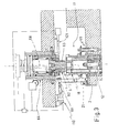
- the unit 14 comprises a punch-carrier cassette 18 constituted by a circular plate 19 housed within a through hole 20 formed in the turret 2 and having its axis 21 parallel to the axis 4, and a tubular body 22 which extends upwardly from the plate 19.
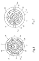
- the cassette 18 is axially movable within the hole 20 and, as illustrated in Figure 6, has eight through holes 23 in the plate 19, equidistant from one another around the circle Band having axes 24 parallel to the axis 21; each hole 23 houses a punch 12 of commercial type.
- the unit 14 further includes a sheet holder device 30 having a circular plate 31 disposed beneath the plate 19 and of diameter substantially equal to the diameter of this plate 19.
- the device 30 further includes a rod 36 of greater length than the thickness of the plate 19, extending axially upwardly from the plate 31 along a central through hole 37 formed in the plate 19.
- the rod 36 is axially slidable along the hole 37 and its free end is threaded so as to be engaged by a nut 38 adapted to prevent the rod 36 from coming out of the plate 19.
- the device 30 is axially movable between a first end position, in which the plate 31 is disposed at a distance from the lower face of the plate 19 and the nut 38 is in abutment against the upper face of the plate 19, and a second end position in which the plate 31 is disposed in contact with the lowerface of the plate 19.
- the central part of the plate 19 in contact with the nut 38 is constituted by a cylindrical body 39 having an axis 21, housed in a cylindrical seat 40 formed on the upper surface of the plate 19.
- the lateral surface of the body 39 has eight axial grooves 41 each of which is engaged by an associated key 42 projecting radially from the shank of an associated punch 12.
- the keys 42 prevent rotation of the punches 12 about their longitudinaly axes during the punching operation, in this way preventing the angle or orientation of the cut from varying.
- the plate 19 has a first and second plurality of holes 43 parallel to the axis 21 and disposed, with constant pitch, respectively round an outer and an inner circle with respect to the circle B.
- the plate 31 has a first and second plurality of holes 44 coaxial to and facing the holes 43, and disposed with the same constant pitch as the holes 43 around outer and inner circles with respect to the circle B.
- Each hole 43 houses one end of an associated spring 43 the other end of which is fitted into a respective hole 44.
- the springs 45 are mounted under compression between the plates 19 and 31 to maintain the device 30 in the first end position.
- the cassette 18 comprises internally and coaxially a cup shape body 47 having a wall 48 which closes the top of the cassette 18.
- the body 47 is provided with eight holes 50 passing through the wall 48 and the side wall 49 of the body 47.
- Each hole 50 is coaxial with an associated hole 23 and houses an associated pin 51 the lower end of which is in contact with the head of an associated punch 12 and the upper end of which projects from the body 47 by a given amount which will be referred to below.
- the body 47 has a groove 50a which defines a flange in the wall 48 itself.
- the groove 50a has a depth substantially equal to the thickness of the wall 49 in such a way that the sections 52 of the pins 51 are exposed so as to be provided with springs 53 and abutment collars 54 fitted around the associated pin 51.
- Each spring 53 is disposed between an associated collar 54 and the flange 48a, and is held under compression to press the associated pin 51 against the head of the associated punch 12.
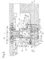
- Each unit 14 is provided with a biasing 55 for the cassette 18 which is axially movable within the hole 20 between a rest position (illustrated in Figure 5) in which the cassette 18, the plate 19 and the device 30 are within the hole 20, and an operative position in which the cassette 18 projects below the turret 2, the sheet holder 33 presses the metal sheet and the device 30 is disposed in the second end position.
- the device 55 includes a tubular body 56 a lower portion of which lies within a blind hole 57 the axis of which is parallel to the axis 21 and formed externally of the unit 14 on the upper face of the turret 2.
- the body 56 is movable axially within the hole 57 and is urged upwardly by a spring 58 disposed between the bottom of the hole 57 and the lower portion of the body 56.
- the stroke of the body 56 is upwardly limited by a stop 58a constituted by a nut and lock nut screwed to the threaded end of a shaft 59 which extends coaxially from the bottom of the hole 57 upwardly through the body 56 to project from the body 56.
- the upper end of the body 56 has a flange 60 which is contacted from above by an annular flange 61 formed on the outer face of the body 22; in this way the action of the spring 58 is transmitted, which tends to bias the cassette 18 from the operative position to the rest position.
- the cassette 18 carries a radial pin 152 engaging an axial groove 153 of the body 47 for the purpose of preventing relative rotation between the body 47 and the cassette 18.
- the station 5 includes a striker device 66 disposed above the turret 2 and comprising a tubular body 67 having an axis 68 housed in a through hole 69 of a support beam 70.
- the beam 70 is fixed to the arm 10 and extends parallel to and above the turret 2.
- the axis 68 is perpendicular to the turret 2 and intersects the circle Aalong which are located the units 11, which, when in the working station 5, are disposed beneath the body 68.
- the axis 21 of a unit 14 is coaxial with the axis 68.
- the body 67 is rotatably mounted on the beam 70 so as to turn about the axis 68 driven by a reversible motor 71 controlled from the central control unit 8. Between the body 67 and the motor 71 there is formed a worm gear coupling comprising a toothed wheel 72 and worm gear 73.
- the body 67 houses a tubular body 74 coaxial with the axis 68 and movable towards and away from the turret 2.
- the body 74 has on its outer lateral surface a longitudinal groove 74 engaged by a radial key carried by the body 67 to tie the body 74 angularly to the body 67 and allow axial movement of the body 74 between an upperend position and a lower end position.
- the body 74 has a pair of teeth 76a extending axially downwardly at diametrically opposite positions with respect to one another.
- the teeth 76a are able to engage a pair of recesses 76b formed at the free end of the body 22, to couple the body 74 and the cassette 18 for rotation together.
- the body 74 is traversed axially by a rod 77 movable axially towards and away from the turret 2 under the action of a linear actuator 78 disposed above the body 67 and controlled by the central control unit 8.
- the rod 77 carries a piston 79 disposed within the body 67 above an upper portion 74a of the body 74, of greater thickness.
- the piston 79 sealingly closes the body 67 to create an annular chamber 80 defined by the body 67, the portion 74a and the piston 79.
- the chamber 80 can be occupied by fluid under pressure conveyed via a first channel 81 within the rod 77. In use, this fluid, in use, causes the body 74 to descend towards the turret 2.
- the rod 77 carries at its lower end a striker mass (hammer) 82 comprising an axially symmetric body 83 coaxial with the axis 68, and an annular body 84 disposed around the body 83.
- the body 83 has an upper portion 85, an intermediate portion 86 and a lower portion 87, all cylindrical and of progressively decreasing diameter in order.
- the portion 85 is connected to the lower end of the rod 77 by a screw 88 and has a diameter substantially equal to the internal diameter to the body 74.
- the portion 85 transversely sealingly closes the body 74 to create an annular chamber 89 defined by the body 74, the rod 77, the portion 85 and the portion 74a.
- the chamber 89 can be filled with fluid under pressure conveyed through a second channel 90 within the rod 77. This fluid causes upward translation of the body 74.
- the portions 86 and 87 are disposed coaxially within the body 84, which is axially fixed to the body 83 by a retaining ring 91 disposed between the portion 86 and the body 84.
- the ring 91 has its radially inner point crown housed in an annular groove 92 formed on the outer surface of the body 83, and a radially outer part housed in an annular groove 93 formed on the internal surface of the body 84.
- the body 84 can be coupled angularly for rotation with the body 83 by a frontal coupling 94.
- the coupling 94 comprises a first flange 95 disposed coaxially about the portion 86 and fixedly mounted to the body 84 by screws 96 (only one of which is illustrated in Figure 8) and a second flange 97 disposed coaxially about the portion 86 and mounted so as to be angularly fixed and axially slidable on the portion 85 by means of axial guides defined by pins 96a fitted in the flange 97 and in the portion 85.
- the flange 97 is movable between an engagement position and a disengagement position (illustrated in Figure 8).
- the flange 97 In the engagement position the flange 97 is pressed against the flange 95 by a plurality of springs 98 (only one of which is illustrated in Figure 8) disposed between the flange 97 and the portion 85 within associated holes 99, and in the disengagement position the flange 97 is held spaced from the flange 95 by a key 100 against the action of the springs 98.
- the key 100 is carried by the body 74 and extends radially towards the axis 68.
- the key 100 When the flange 97 is in the disengagement position the key 100 is disposed in contact against the flange 97 and engages a longitudinal slot 1 OOa formed on the flange 95 to connect the body 74 for rotation with the body 84.
- the body 84 In the disengagement position, therefore, the body 84 is uncoupled from the body 83 and coupled to the body 74.
- the flange 95 is in contact with an annular flange 84a defined at the upper end of the body 84 and having an axial slot 84b coaxial to the slot 100a.
- the body 84 has on its lateral surface a longitudinal rib 101 which extends downwardly parallel to the axis 68 and has a radial dimension lying between the outer lateral surface of the body 84 and the inner lateral surface of the body 22.
- the thickness of the rib 101 ( Figure 7) is less than the distance between two adjacent pins 51 so that it can lie over a single punch 12.
- the rib 101 extends downwardly less than the downward extent of the body 83.
- a lower surface 102 of the body 83 is spaced from a lower surface 103 of the rib 101 by an amount equal to that by which the pins 51 project from the upper end of the cassette 18. In this way when, in use, the hammer 82 is displaced downwardly, the body 83 and the rib 101 are simultaneously disposed in contact with the upper face of the wall 48 and the upper end of the pin 51 respectively.
- the station 5 includes a locking device 105 operable to limit the downward stroke of the body 74 so as to dispose this in an intermediate position lying between the upper and lower end of stroke positions.
- the device 105 includes a slide 106 slidable on a guide mounted beneath the beam 70 by the action of a linear actuator 107 controlled by the central control unit 8.
- the slide 106 translates along a radial direction 104 towards and away from the axis 68 between an operative position and a rest position. In the operative position of the slide 106 its end 108 is so positioned that, during the downward stroke of the body 74 an outer annular flange 109 formed on the lower end of this body 74 comes into contact with it.
- Each unit 14 is provided with a key 111 mounted movably on the turret 2 outside and radially of the cassette 18.
- the key 111 is displaceable between a position (illustrated in Figure 5) in engagement with a longitudinal groove 112, with which the cassette 18 is provided on its outer surface, and a position of disengagement from the groove 112. In the engagement position the key 111 locks the cassette 18 in an angular reference position in which the recesses 76b are disposed parallel to the direction 104.
- the key 111 has a projection 117 which extends upwardly beyond the upper face of the turret 2.
- the station 5 includes a release device 110 operable to displace the key 111 by the action of a linear actuator 113 ( Figure 4) controlled by the central control unit 8 and carried by the beam 70.
- the actuator 113 controls the translation towards and away from the axis 68 of its rod 114 which, by means of a lever mechanism 115, controls translation of the key 111.
- the mechanism 115 has a lever 151 in the lower end of which is formed a slot 116.
- the key 111 is always in the engagement position in the groove 112 and the projection 117 is in a position such as to allow traversing of the slot 116.
- the projection 117 engages the slot 116 so that the movement of the rod 114 causes, via the mechanism 115, movement of the key 111 and therefore unlocking of the cassette 18.
- the turret 3 is of known type and can turn about the axis 4 under the action of a motor not illustrated.
- the turret 3 carries die units 118 provided with dies 119 each of which corresponds to an associated punch 12 of the units 13, 14, 15 and 16.
- the units 118 are disposed on the turret 3 in an arrangement identical to that in which the punch units 11 are disposed on the turret 2 so as to position, in use, a unit 118 beneath an associated unit 11 transferred to the station 5.
- the metal sheet to be punched is disposed between the turrets 2 and 3, mounted on the carriage 6 of known type which, under the control of the central control unit 8, can move the said metal sheet to transfer different portions of the metal sheet in succession under the station 5.
- the central control unit 8 is of known type and allows selective actuation of the turrets 2 and 3, the motor 71, the actuator 78, the carriage 6 and the devices 105 and 110 by means of programmes of known type.
- the pre-selected punch 12 forms part of a unit 14 this is transferred and stopped at the station 5, and the projection 117 of the key 111 is inserted into the slot 116.
- the device 110 is actuated to display the key 111 into its disengaged position so as to unlock the cassette 18 for turning movement.
- the body 74 is turned to rotate the rib 101, via the key 100, to a pre-selected working position.
- the device 105 is actuated to translate the slide 106 towards the operative position, and the body 74 is lowered until it is locked in the said intermediate position.
- the locking of the body 74 causes engagement of the flange 97 against the flange 95 by the actions of the springs 98; the rib 101 is thus fixedly secured to the body 83 and prevented from rotating.
- the body 74 is turned to return it to the initial position in which the teeth 76a are disposed above the recesses 76b; this rotation does not involve rotation of the rib 101 in that the key 100 remains outside the slot 100a.
- the body 74 is completely lowered. This lowering carries the body 74 into the lower end position in which the teeth 76a engage the recesses 76b so that the body 74 and the cassette 18 are coupled for rotation together.
- the body 74 is turned to rotate the cassette 18 and carry the punch 12 to be struck beneath the rib 101.
- the body 74 is maintained in its lower end position to define a precise reference for the angular position of the cassette 18 during punching.
- the rod 77 is raised. During this displacement the cassette 18 is held up by the device 55 and the springs 45 progressively return the device 30 into the first end position, allowing the punch 12 to be withdrawn from the metal sheet. Then the body 74 is rotated to return the cassette 18 into the reference position and allow the device 110 to lock the cassette 18 by displacement of the key 111. Following this the body 74 is raised to bring the key 100 into contact with the flange 84a, the device 105 is actuated to translate the slide 106 towards the axis 68, the body 74 is translated downwardly to engage on the end 108 of the slide 106, and finally the body 74 is turned to bring the key 100 into alignment with the slots 84b and 100a.
- the body 7 is caused to translate upwardly and subsequently rotate to bring the rib 101 into its reference position.
- the carriage 6 moves the metal sheet to bring another portion thereof into the station 5 in correspondence with which the turrets 2 and 3, by rotating, carry another unit 11 into the station 5.
- the punch 12 to be struck belongs to a unit 13, after having transferred and stopped this unit 13 in the station 5 the rod 77 is translated downwardly in such a way that the body 83 strikes the punch 12. If the punch 12 to be struck belongs to a unit 15, after having transferred the corresponding unit 11 and stopped it in the station 5, in the same way as described for the unit 14, rotation of the rib 101 is controlled to bring this into alignment with the punch 12 to be struck and the rod 77 is made to translate downwardly in such a way that the rib 101 strikes the punch 12. If the punch 12 to be struck belongs to a unit 16 the pair of units 16 of which the pre-selected unit 16 forms part is transferred and stopped in the station 5.
- the units 13, 15, and 16 as already indicated are units of known type and in particular are also provided with sheet holder devices and biasing devices.
- the machine 1 is provided with a working station in which the striking device, because of the possibility of varying at will the angular position of the rib 101 with respect to the striking axis, can work on punches disposed around the circle A and on punches disposed to one side of this circle A as, for example, the punches disposed around the circles B and C and along the arcs D' and D".
- the possibility of angularly orientating the rib 101 allows the machine 1 to carry punches of different dimensions and above all to be provided with a greater number of punches of greater length than the number of such punches with which current punch presses machines are provided; because of this the machine 1 has a high productive capacity.
- the striking device is able to vary the position along the circle B of the punch to be struck and therefore it is not only possible to prearrange the punch in a given striking position in the machine 1, but also to vary its angle of cutting orientation.
- the high number of punches and the possibility of varying for some of these the striking point and the angle of cutting orientation involves a significant reduction in punching costs in that a single machine 1 can perform the functions of two current machines.
- the unit 14 is of relatively simpler construction than those units provided with intermediate bodies disposed between the hammer and punch in that an element rotatable with respect to the cassette is not present.
- commercial punches are utilised in the unit 14 described above, thanks to the presence of the pins 51 and the particular configuration of the hammer 82.
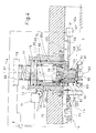
- FIG. 2 there is shown a variant of the unit 13, indicated 13a.
- the unit 13a is a single punch and includes a punch-carrier cassette 120 within which the punch 12 is mounted coaxially.
- the cassette 120 has slots 121 which can be engaged by teeth 76a to be rotated by the body 74 about the axis 68 when the unit 13a is stopped in the station 5. Rotation of the cassette 120 causes rotation of the punch 12 to cause punching at a pre-selected angle of cutting orientation.
- the unit 16 disposed along the arc D' could be chosen to be offset or in phase with the units 16 disposed along the arc D".
- the unit 11 constituted by the units 15 could be provided with an external rotatable cassette having recesses similar to the recesses 76b for coupling with the body 74 so as to be rotated.
- the external cassette could then have, along its inner lateral surface, a toothed annular portion meshing with respective toothed annular portions formed in the punch-carrier cassette of each unit 15.
- Rotation of the outer cassette would involve rotation along its longitudinal axis of each punch-carrier cassette and therefore rotation about its longitudinal axis of each punch. In this way even if the units 15 could not rotate around the circle C the rotation of the punches about their respective longitudinal axes makes it possible for each punch to be orientable to any angle of cutting orientation.
- the outer cassette could be rotated by a drive device via, for example, a worm gear coupling.
- the punch press machine in place of the turret 2 and 3 the punch press machine could be provided with a chain transfer device as described in Italian Patent application No 3350A/89 by the same applicant.
- the chain could carry a plurality of punch units 11 constituted by a unit 13 or 13a, a unit 14 or by several units 15 disposed around the circle C, and at least one pair of units 16.
Landscapes
- Engineering & Computer Science (AREA)
- Mechanical Engineering (AREA)
- Punching Or Piercing (AREA)
- Perforating, Stamping-Out Or Severing By Means Other Than Cutting (AREA)
Applications Claiming Priority (2)
| Application Number | Priority Date | Filing Date | Title |
|---|---|---|---|
| ITBO920079A IT1257758B (it) | 1992-03-10 | 1992-03-10 | Macchina punzonatrice |
| ITBO920079 | 1992-03-10 |
Publications (1)
| Publication Number | Publication Date |
|---|---|
| EP0560333A1 true EP0560333A1 (fr) | 1993-09-15 |
Family
ID=11338053
Family Applications (1)
| Application Number | Title | Priority Date | Filing Date |
|---|---|---|---|
| EP93103866A Withdrawn EP0560333A1 (fr) | 1992-03-10 | 1993-03-10 | Une machine à poinçonner |
Country Status (2)
| Country | Link |
|---|---|
| EP (1) | EP0560333A1 (fr) |
| IT (1) | IT1257758B (fr) |
Cited By (6)
| Publication number | Priority date | Publication date | Assignee | Title |
|---|---|---|---|---|
| US5528968A (en) * | 1994-04-14 | 1996-06-25 | Murata Machinery, Ltd. | Punch press with automated sheet rotation |
| EP0818253A3 (fr) * | 1996-07-12 | 1998-03-25 | C. Behrens AG | Poinçonneuse à revolver |
| EP1057551A1 (fr) * | 1999-05-25 | 2000-12-06 | RAINER S.r.l. | Unité à poinçon multiple et machine outil pourvu d'une telle unité à poinçon multiple |
| EP1595614A1 (fr) * | 2004-05-12 | 2005-11-16 | Goiti, S.Coop | Machine à poinçonner |
| CN102423781A (zh) * | 2011-11-29 | 2012-04-25 | 大连大显精密轴有限公司 | 一种楔块紧固式轴类工件压筋胎具 |
| WO2020083866A1 (fr) * | 2018-10-22 | 2020-04-30 | Ehrt Maschinenbau Gmbh | Outil d'estampage |
Citations (5)
| Publication number | Priority date | Publication date | Assignee | Title |
|---|---|---|---|---|
| DE1138613B (de) * | 1959-12-01 | 1962-10-25 | Voith Gmbh J M | Vorrichtung zum Stanzen von wenigstens angenaehert kreisfoermigen Scheiben |
| DE2264851B2 (de) * | 1971-02-19 | 1977-06-02 | U.S. Amada Ltd., Seattle, Wash. (V.StA.) | Revolverstanzpresse |
| US4250785A (en) * | 1979-06-02 | 1981-02-17 | Yamazaky Iron Works | Turret type punch press having a plurality of strikers |
| EP0108935A2 (fr) * | 1982-11-06 | 1984-05-23 | Trumpf GmbH & Co | Presse à estamper à poinçon multiple |
| DE3912871A1 (de) * | 1988-04-25 | 1989-11-02 | Pullmax Ab | Werkzeugbefestigung fuer stanzwerkzeug |
-
1992
- 1992-03-10 IT ITBO920079A patent/IT1257758B/it active IP Right Grant
-
1993
- 1993-03-10 EP EP93103866A patent/EP0560333A1/fr not_active Withdrawn
Patent Citations (5)
| Publication number | Priority date | Publication date | Assignee | Title |
|---|---|---|---|---|
| DE1138613B (de) * | 1959-12-01 | 1962-10-25 | Voith Gmbh J M | Vorrichtung zum Stanzen von wenigstens angenaehert kreisfoermigen Scheiben |
| DE2264851B2 (de) * | 1971-02-19 | 1977-06-02 | U.S. Amada Ltd., Seattle, Wash. (V.StA.) | Revolverstanzpresse |
| US4250785A (en) * | 1979-06-02 | 1981-02-17 | Yamazaky Iron Works | Turret type punch press having a plurality of strikers |
| EP0108935A2 (fr) * | 1982-11-06 | 1984-05-23 | Trumpf GmbH & Co | Presse à estamper à poinçon multiple |
| DE3912871A1 (de) * | 1988-04-25 | 1989-11-02 | Pullmax Ab | Werkzeugbefestigung fuer stanzwerkzeug |
Cited By (7)
| Publication number | Priority date | Publication date | Assignee | Title |
|---|---|---|---|---|
| US5528968A (en) * | 1994-04-14 | 1996-06-25 | Murata Machinery, Ltd. | Punch press with automated sheet rotation |
| EP0818253A3 (fr) * | 1996-07-12 | 1998-03-25 | C. Behrens AG | Poinçonneuse à revolver |
| EP1057551A1 (fr) * | 1999-05-25 | 2000-12-06 | RAINER S.r.l. | Unité à poinçon multiple et machine outil pourvu d'une telle unité à poinçon multiple |
| EP1595614A1 (fr) * | 2004-05-12 | 2005-11-16 | Goiti, S.Coop | Machine à poinçonner |
| CN102423781A (zh) * | 2011-11-29 | 2012-04-25 | 大连大显精密轴有限公司 | 一种楔块紧固式轴类工件压筋胎具 |
| CN102423781B (zh) * | 2011-11-29 | 2013-06-12 | 大连大显精密轴有限公司 | 一种楔块紧固式轴类工件压筋胎具 |
| WO2020083866A1 (fr) * | 2018-10-22 | 2020-04-30 | Ehrt Maschinenbau Gmbh | Outil d'estampage |
Also Published As
| Publication number | Publication date |
|---|---|
| ITBO920079A0 (it) | 1992-03-10 |
| IT1257758B (it) | 1996-02-13 |
| ITBO920079A1 (it) | 1993-09-10 |
Similar Documents
| Publication | Publication Date | Title |
|---|---|---|
| US4569267A (en) | Multitool punch mechanism | |
| US5072620A (en) | Stamping tool | |
| CA1327881C (fr) | Tourelle indexable a outils multiples pour poinconneuse | |
| EP0399338B1 (fr) | Porte-outil multiple pour poinçons | |
| US4570313A (en) | Spindle lock-up device | |
| US4779329A (en) | Tool changer for rotatable tool assemblies in punching machines | |
| US6675688B2 (en) | Modular unit for converting punching machines from single-punch to multiple-punch | |
| CN100384560C (zh) | 冲床 | |
| JP2945682B2 (ja) | 打抜き工具用のツールホルダー | |
| EP1863608B1 (fr) | Support d'outil de travail de métal pour une utilisation avec un tour portable pouvant se fixer et usiner la circonférence d'un tube | |
| US5848563A (en) | Multiple tool for punch press | |
| US5615471A (en) | Machine for machining sheet metal | |
| US5201589A (en) | Marking tool holder for a punch press | |
| JPH07136724A (ja) | タレットパンチプレス | |
| US5544989A (en) | Apparatus for making a drilled hole with an undercut | |
| FI3450042T3 (fi) | Monitoimityökalu | |
| EP0583537B1 (fr) | Dispositif pour la sélection et l'orientation d'un outil de découpage pour une presse de découpage | |
| KR100348143B1 (ko) | 펀칭 프레스 | |
| EP1057551A1 (fr) | Unité à poinçon multiple et machine outil pourvu d'une telle unité à poinçon multiple | |
| AU640541B2 (en) | Drilling and chiselling device | |
| JP4341368B2 (ja) | パンチプレス | |
| JPH06126533A (ja) | タレットパンチプレス | |
| US1992558A (en) | Turning, forming, and threading attachment for drill presses | |
| SU1496870A1 (ru) | Пробивной револьверный пресс | |
| SU1180118A1 (ru) | Револьверный дыропробивной пресс |
Legal Events
| Date | Code | Title | Description |
|---|---|---|---|
| PUAI | Public reference made under article 153(3) epc to a published international application that has entered the european phase |
Free format text: ORIGINAL CODE: 0009012 |
|
| AK | Designated contracting states |
Kind code of ref document: A1 Designated state(s): AT BE CH DE ES FR GB LI NL SE |
|
| 18D | Application deemed to be withdrawn |
Effective date: 19940316 |