EP1057551A1 - Unité à poinçon multiple et machine outil pourvu d'une telle unité à poinçon multiple - Google Patents
Unité à poinçon multiple et machine outil pourvu d'une telle unité à poinçon multiple Download PDFInfo
- Publication number
- EP1057551A1 EP1057551A1 EP99830316A EP99830316A EP1057551A1 EP 1057551 A1 EP1057551 A1 EP 1057551A1 EP 99830316 A EP99830316 A EP 99830316A EP 99830316 A EP99830316 A EP 99830316A EP 1057551 A1 EP1057551 A1 EP 1057551A1
- Authority
- EP
- European Patent Office
- Prior art keywords
- cassette
- punch
- unit
- tool
- rotation
- Prior art date
- Legal status (The legal status is an assumption and is not a legal conclusion. Google has not performed a legal analysis and makes no representation as to the accuracy of the status listed.)
- Withdrawn
Links
- 239000002184 metal Substances 0.000 claims description 15
- 238000004080 punching Methods 0.000 claims description 9
- 239000012530 fluid Substances 0.000 claims description 2
- 238000010276 construction Methods 0.000 description 1
- 238000012986 modification Methods 0.000 description 1
- 230000004048 modification Effects 0.000 description 1
- 230000002093 peripheral effect Effects 0.000 description 1
- 230000001681 protective effect Effects 0.000 description 1
Images

Classifications
-
- B—PERFORMING OPERATIONS; TRANSPORTING
- B21—MECHANICAL METAL-WORKING WITHOUT ESSENTIALLY REMOVING MATERIAL; PUNCHING METAL
- B21D—WORKING OR PROCESSING OF SHEET METAL OR METAL TUBES, RODS OR PROFILES WITHOUT ESSENTIALLY REMOVING MATERIAL; PUNCHING METAL
- B21D28/00—Shaping by press-cutting; Perforating
- B21D28/02—Punching blanks or articles with or without obtaining scrap; Notching
- B21D28/12—Punching using rotatable carriers
- B21D28/125—Punching using rotatable carriers with multi-tools
-
- B—PERFORMING OPERATIONS; TRANSPORTING
- B21—MECHANICAL METAL-WORKING WITHOUT ESSENTIALLY REMOVING MATERIAL; PUNCHING METAL
- B21D—WORKING OR PROCESSING OF SHEET METAL OR METAL TUBES, RODS OR PROFILES WITHOUT ESSENTIALLY REMOVING MATERIAL; PUNCHING METAL
- B21D28/00—Shaping by press-cutting; Perforating
- B21D28/02—Punching blanks or articles with or without obtaining scrap; Notching
- B21D28/12—Punching using rotatable carriers
Definitions
- the present invention relates to a multiple punch unit.
- the present invention also relates to a machine tool for working sheet metal provided with an innovative multiple punch unit.
- a multiple punch unit comprises a single tool holder cassette within which a plurality of punches are installed in a circle.
- a first type of multiple punch unit has a body installed within the tool holder cassette supporting a striker and rotating about a vertical axis to bring the striker into alignment with a pre-selected punch.
- a second type of multiple punch unit has a body installed within the cassette and supporting the striker; the cassette being rotatable about a vertical axis to carry the pre-selected punch into alignment with the striker.
- a third type of multiple punch unit provides an external striker outside the tool holder cassette and rotatable about a vertical axis to bring a projection thereof into alignment with a pre-selected punch; the cassette being rotatable about the said vertical axis to orientate the pre-selected punch.
- the main disadvantage of this type of multiple punch unit lies in its large dimensions and in the complexity of construction in that two different motor drives are needed, one for the cassette and the other for the striker.
- the object of the present invention is that of providing a multiple punch unit which will be free from the above-mentioned disadvantages.
- a further object of the present invention is that of providing a machine tool having a multiple punch unit free from the above-mentioned disadvantages.
- a multiple punch unit characterised in that it comprises:
- a machine tool for punching a metal sheet comprising:
- a machine tool generally indicated 1 for working sheet metal 2 comprises:
- the work unit 5 comprises:
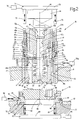
- At least one of the punch units 11 carried by the turret 8 is a multiple punch unit and is illustrated in Figure 2 as multiple punch unit 18 which comprises a cassette 21 shaped like a cylindrical cup and rotatable about its vertical longitudinal axis P.
- the cassette 21 has a bottom wall 22 and an annular side wall 23 which extends upwardly from the peripheral rim of the bottom wall 22. Close to the bottom wall 22, but at a given distance from it, and within the cassette 21 there is installed a disc 24 having an axis P fixed for rotation with the cassette 21 by means of a key 25 carried by the wall 23 and engaging an axial groove 26 formed on the lateral face of the disc 24.
- the disc 24 is movable along the axis P and between it and the bottom wall 22 there is installed a coil spring 27 opposing the translation of the disc 24 towards the bottom wall 22.
- the disc 24 has around its periphery a plurality of vertical through holes 28.
- the disc 24 supports a plurality of punch tools 31 each having a shank 31a which traverses a respective hole 28, and a head 31b which rests on the upper face of the disc in correspondence with the edge of the respective hole 28.
- the bottom wall 22 has around its periphery a plurality of vertical through holes 32 coaxial with the holes 28.
- the shank 31a lies within a corresponding hole 32 and its tip projects from the hole 32 up to the interior of a recess 33 formed on the lower face of the bottom wall 22.
- the projection 35 has a smaller diameter and is in engagement with the upper face of the disc 24.
- a striker 36 fixed to the body 34 by means of a fixing screw 37 extends downwardly along a vertical axis A.
- a cylindrical pad 39 on the axis P which is pressed against the heads 31b of the punch tool 31 by a coil spring 38 installed between the pad 37 and the lower face of the body 34.
- the pad 37 has a through hole 40 on the axis P traversed by the projection 35.
- the pad 37 further has a second through hole 41 having an axis A traversed by the striker 36 the lower end of which comes into contact with the head 31b of one of the punch tools 31.
- a pin 45 having an axis M axially fixes the cassette 21 and the body 34 together.
- the pin 45 traverses the sections 42b and 42c of the hole 42, the hole 40 of the pad 39, a through hole 46 formed in the disc 24, and a through hole 47 formed in the bottom wall 22.
- the pin 45 allows the body 34 to rotate about the axis M with respect to the cassette 31. From the top towards the bottom the pin 45 has a head 45a which engages the shoulder 43, a section 45b housed in the sections 42b and 42c, an annular projection 45c housed in the section 42c and in contact against the disc 24, a section 45d housed in the holes 46 and 47, and an end fixed by means of a screw to the bottom wall 22.
- the turret 8 has a through hole 48 on the axis P engaged by a sleeve 51 housing the lower part of the cassette 21.
- a key 52 carried by the turret 8 by a known means 52a between a position in which it extends into an axial groove 53 formed in the wall 23 to prevent rotation of the cassette 21 about the axis P, and a disengaged position in which it lies outside this groove 53.
- the cassette 21 supports a cylindrical sleeve 54 on the axis P and a lower portion which lies inside the upper part of the wall 25 and an upper portion which lies within the upper part of the body 34.
- a toothed annular zone 55 meshing with a toothed annular zone 56 formed on the outer face of the upper part of the body 34.
- a vertical hole 58 is formed in the sleeve 54 in correspondence with one notch 57a, which opens into a through slot 61.
- a pin 62 is housed in the hole 58 and has an upper end which extends into the notch 57a and a lower end which extends into the slot 61 and which carries a key 63.
- the pin 62 is movable, against the action of a spring 64 housed in the slot 61, between an upper position in which the key 63 engages a toothed annular zone 65 formed at the upper end of the part 23, and a lower position in which the key is disengaged from the toothed zone 65.
- rotation of the sleeve 54 about the axis P involves an equal rotation both of the cassette 21 and therefore the disc 24, and of the body 34.
- a rotation of the sleeve 54 about the axis P involves an equal rotation only of the body 34.
- the machine 1 includes a device 71 for selection of the punch tool 31 to be utilised and for the adjustment of the angular orientation of the selected punch tool 31.
- the device 71 comprises an annular body 72 on axis M, two vertical teeth 73 which extend downwardly from the lower end of the body 72 and which are diametrically opposite one another, and means 74 for rotation of the body 72 about the axis M and for vertical translation of the body 72.
- the die unit 13 comprises a cassette 75 having a vertical axis T, housed, with the interposition of a sleeve 76, within a vertical through hole 77 formed in the turret 12.
- the cassette 75 houses a cylindrical body 78 centred on axis T with a plurality of vertical through holes 81 in a ring, each of which is engaged by a corresponding die tool 82; in use, when the axis P of the multiple punch unit 18 and the axis T of the die unit 13 are coaxial with the axis M of the hammer 14 the holes 81 are coaxial with respective holes 32 such that each punch tool 31 is coupled with a corresponding die tool 82.
- the body 78 is fixed against rotation with respect to the cassette 75.
- a key 83 carried by the turret 12 is able to translate, by means 84 of known type, between an engaged position in a groove 85 formed in the cassette 75 in such a way as to prevent rotation of this, and a disengaged position in which the cassette 75 is free to rotate about the axis T.
- the machine 1 includes a device 87 for selection of the die tool 82 to be utilised and for adjusting the angular orientation of the selected die tool 82.
- the device 87 includes an annular body 88 on axis T, two vertical teeth 91 which extend upwards from the upper end of the body 88 and which are diametrically opposite one another, and means 92 for rotation of the body 88 about the axis T and for vertical translation of the body 88.
- the multiple punch unit 18 and the corresponding die unit 13 are brought into alignment with the hammer 14.
- the body 72 turns until the teeth 73 are in alignment with the notches 57a, then the body 72 translates downwardly until the teeth 73 engage the notches 57a and one of the teeth 73 disengages the key 63 from the toothed zone 65 by means of the pin 62, and finally the body 72 turns in such a way as to bring the striker 36 into alignment with the punch tool 31 to be utiised.
- the body 72 translates upwardly in such a way as to disengage the teeth 73 from the notches 57a, then the body 72 turns through 90°, subsequently the body 72 translates downwardly until the teeth 73 engage the notches 57b and finally the body 72 turns until, with the same rotation of the cassette 21 and the body 34, it reaches the pre-selected angular orientation of the selected punch tool 31.
- the cassette 75 turns by means of the device 87 in such a way as to make the die tool 82 coupled to the selected punch tool 31 reach the same angular orientation.
- these must be free to rotate and therefore the respective keys 52 and 83 are in the disengaged position.
- the body 34 translates downwardly and causes an equal translation of the striker 36 which acts only on the selected punch tool 31; the bottom wall 22 acting as a sheet presser.
- a compact multiple punch unit therefore having reduced dimensions, is formed incorporating therein the punch tools and the striker. Moreover it is possible easily to select the punch tool to be utilised and it is possible to determine with ease the angular orientation at which the punch tool is to be set.
Landscapes
- Engineering & Computer Science (AREA)
- Mechanical Engineering (AREA)
- Perforating, Stamping-Out Or Severing By Means Other Than Cutting (AREA)
Priority Applications (1)
| Application Number | Priority Date | Filing Date | Title |
|---|---|---|---|
| EP99830316A EP1057551A1 (fr) | 1999-05-25 | 1999-05-25 | Unité à poinçon multiple et machine outil pourvu d'une telle unité à poinçon multiple |
Applications Claiming Priority (1)
| Application Number | Priority Date | Filing Date | Title |
|---|---|---|---|
| EP99830316A EP1057551A1 (fr) | 1999-05-25 | 1999-05-25 | Unité à poinçon multiple et machine outil pourvu d'une telle unité à poinçon multiple |
Publications (1)
| Publication Number | Publication Date |
|---|---|
| EP1057551A1 true EP1057551A1 (fr) | 2000-12-06 |
Family
ID=8243415
Family Applications (1)
| Application Number | Title | Priority Date | Filing Date |
|---|---|---|---|
| EP99830316A Withdrawn EP1057551A1 (fr) | 1999-05-25 | 1999-05-25 | Unité à poinçon multiple et machine outil pourvu d'une telle unité à poinçon multiple |
Country Status (1)
| Country | Link |
|---|---|
| EP (1) | EP1057551A1 (fr) |
Cited By (5)
| Publication number | Priority date | Publication date | Assignee | Title |
|---|---|---|---|---|
| EP1447154A3 (fr) * | 2003-02-06 | 2004-10-20 | Murata Kikai Kabushiki Kaisha | Presse à poinçonner |
| EP2210684A1 (fr) * | 2009-01-27 | 2010-07-28 | TRUMPF Werkzeugmaschinen GmbH + Co. KG | Outil pour une machine de poinçonnage dotée de plusieurs ensembles d'outils oscillants |
| ITMO20130149A1 (it) * | 2013-05-27 | 2014-11-28 | Salvagnini Italia Spa | Apparato di punzonatura |
| EP3213835A1 (fr) * | 2013-05-27 | 2017-09-06 | SALVAGNINI ITALIA S.p.A. | Machine à poinçonner |
| CN116422755A (zh) * | 2023-04-20 | 2023-07-14 | 江苏群业电工有限公司 | 一种缠绕电缆用的线盘冲压成型设备 |
Citations (9)
| Publication number | Priority date | Publication date | Assignee | Title |
|---|---|---|---|---|
| EP0388644A2 (fr) * | 1989-02-21 | 1990-09-26 | RAINER S.r.l. | Machine à poinçonner la tôle |
| EP0560333A1 (fr) * | 1992-03-10 | 1993-09-15 | RAINER S.r.l. | Une machine à poinçonner |
| EP0579217A1 (fr) * | 1992-07-14 | 1994-01-19 | Amada Metrecs Company, Limited | Outil multiple pour poinçonneuse |
| EP0580124A1 (fr) * | 1992-07-21 | 1994-01-26 | Amada Metrecs Company, Limited | Outil multiple pour poinçonneuse |
| EP0583537A1 (fr) * | 1992-08-20 | 1994-02-23 | Murata Machinery Ltd. | Dispositif permettant de découper dans diverses directions avec chaque outil d'un porte-outil à plusieurs outils |
| DE4402427A1 (de) * | 1993-01-29 | 1994-08-04 | Rainer Srl | Stanze |
| DE4444858A1 (de) * | 1993-12-24 | 1995-06-29 | Rainer Srl | Lochstanze |
| DE4445363A1 (de) * | 1993-12-24 | 1995-07-13 | Rainer Srl | Blechbearbeitungsmaschine |
| EP0818253A2 (fr) * | 1996-07-12 | 1998-01-14 | C. Behrens AG | Poinçonneuse à revolver |
-
1999
- 1999-05-25 EP EP99830316A patent/EP1057551A1/fr not_active Withdrawn
Patent Citations (9)
| Publication number | Priority date | Publication date | Assignee | Title |
|---|---|---|---|---|
| EP0388644A2 (fr) * | 1989-02-21 | 1990-09-26 | RAINER S.r.l. | Machine à poinçonner la tôle |
| EP0560333A1 (fr) * | 1992-03-10 | 1993-09-15 | RAINER S.r.l. | Une machine à poinçonner |
| EP0579217A1 (fr) * | 1992-07-14 | 1994-01-19 | Amada Metrecs Company, Limited | Outil multiple pour poinçonneuse |
| EP0580124A1 (fr) * | 1992-07-21 | 1994-01-26 | Amada Metrecs Company, Limited | Outil multiple pour poinçonneuse |
| EP0583537A1 (fr) * | 1992-08-20 | 1994-02-23 | Murata Machinery Ltd. | Dispositif permettant de découper dans diverses directions avec chaque outil d'un porte-outil à plusieurs outils |
| DE4402427A1 (de) * | 1993-01-29 | 1994-08-04 | Rainer Srl | Stanze |
| DE4444858A1 (de) * | 1993-12-24 | 1995-06-29 | Rainer Srl | Lochstanze |
| DE4445363A1 (de) * | 1993-12-24 | 1995-07-13 | Rainer Srl | Blechbearbeitungsmaschine |
| EP0818253A2 (fr) * | 1996-07-12 | 1998-01-14 | C. Behrens AG | Poinçonneuse à revolver |
Cited By (8)
| Publication number | Priority date | Publication date | Assignee | Title |
|---|---|---|---|---|
| EP1447154A3 (fr) * | 2003-02-06 | 2004-10-20 | Murata Kikai Kabushiki Kaisha | Presse à poinçonner |
| EP2210684A1 (fr) * | 2009-01-27 | 2010-07-28 | TRUMPF Werkzeugmaschinen GmbH + Co. KG | Outil pour une machine de poinçonnage dotée de plusieurs ensembles d'outils oscillants |
| ITMO20130149A1 (it) * | 2013-05-27 | 2014-11-28 | Salvagnini Italia Spa | Apparato di punzonatura |
| EP3213835A1 (fr) * | 2013-05-27 | 2017-09-06 | SALVAGNINI ITALIA S.p.A. | Machine à poinçonner |
| US10144046B2 (en) | 2013-05-27 | 2018-12-04 | Salvagnini Italia S.P.A. | Punching apparatus |
| US11103912B2 (en) | 2013-05-27 | 2021-08-31 | Salvagnini Italia S.P.A. | Punching apparatus |
| CN116422755A (zh) * | 2023-04-20 | 2023-07-14 | 江苏群业电工有限公司 | 一种缠绕电缆用的线盘冲压成型设备 |
| CN116422755B (zh) * | 2023-04-20 | 2024-01-16 | 江苏群业电工有限公司 | 一种缠绕电缆用的线盘冲压成型设备 |
Similar Documents
| Publication | Publication Date | Title |
|---|---|---|
| US4938264A (en) | Routing cutter | |
| JPH02303636A (ja) | パンチ・プレスのための指標がつけられるマルチ・ツール | |
| US4478540A (en) | Spindle head assembly with oblique axis of rotation | |
| US4594033A (en) | Boring tool for producing undercuts in holes | |
| US4360048A (en) | Power driven, hand operated plane | |
| US5615471A (en) | Machine for machining sheet metal | |
| EP1057551A1 (fr) | Unité à poinçon multiple et machine outil pourvu d'une telle unité à poinçon multiple | |
| JPH0390226A (ja) | マルチツールパンチホルダ | |
| EP0583537B1 (fr) | Dispositif pour la sélection et l'orientation d'un outil de découpage pour une presse de découpage | |
| JPH02502268A (ja) | 工具の伸長長さと直径とを自動的に調整および測定するための機械 | |
| EP1166929B1 (fr) | Outil combiné | |
| US6038947A (en) | Quick return feed for machine tool | |
| US4135278A (en) | Automatic tool changing device for a machining center | |
| EP1747087B1 (fr) | Porte-outil sur tourelle pour presse | |
| EP3752320B1 (fr) | Machine de transfert améliorée | |
| US5791841A (en) | Quill interlock | |
| US4473937A (en) | System for automatic fine adjustment of tools | |
| EP0560333A1 (fr) | Une machine à poinçonner | |
| JPS61178114A (ja) | ねじ立てアタツチメントと割出装置 | |
| US4183270A (en) | Device for changing and fixing tools quickly | |
| JPH06126350A (ja) | タレットパンチプレス | |
| JP4443380B2 (ja) | 工具マガジン装置およびこれを備えた立形マシニングセンタ | |
| JP4374635B2 (ja) | 工具交換装置 | |
| GB2370250A (en) | Automated engraving apparatus | |
| US5454747A (en) | Faceting machine |
Legal Events
| Date | Code | Title | Description |
|---|---|---|---|
| PUAI | Public reference made under article 153(3) epc to a published international application that has entered the european phase |
Free format text: ORIGINAL CODE: 0009012 |
|
| AK | Designated contracting states |
Kind code of ref document: A1 Designated state(s): AT BE CH CY DE DK ES FI FR GB GR IE IT LI LU MC NL PT SE |
|
| AX | Request for extension of the european patent |
Free format text: AL;LT;LV;MK;RO;SI |
|
| AKX | Designation fees paid | ||
| STAA | Information on the status of an ep patent application or granted ep patent |
Free format text: STATUS: THE APPLICATION IS DEEMED TO BE WITHDRAWN |
|
| 18D | Application deemed to be withdrawn |
Effective date: 20010607 |
|
| REG | Reference to a national code |
Ref country code: DE Ref legal event code: 8566 |