EP0560593A2 - Bildschirmvorrichtung für AV-System - Google Patents
Bildschirmvorrichtung für AV-System Download PDFInfo
- Publication number
- EP0560593A2 EP0560593A2 EP93301823A EP93301823A EP0560593A2 EP 0560593 A2 EP0560593 A2 EP 0560593A2 EP 93301823 A EP93301823 A EP 93301823A EP 93301823 A EP93301823 A EP 93301823A EP 0560593 A2 EP0560593 A2 EP 0560593A2
- Authority
- EP
- European Patent Office
- Prior art keywords
- audio
- visual
- unit
- displayed
- control
- Prior art date
- Legal status (The legal status is an assumption and is not a legal conclusion. Google has not performed a legal analysis and makes no representation as to the accuracy of the status listed.)
- Granted
Links
Images





Classifications
-
- H—ELECTRICITY
- H04—ELECTRIC COMMUNICATION TECHNIQUE
- H04N—PICTORIAL COMMUNICATION, e.g. TELEVISION
- H04N21/00—Selective content distribution, e.g. interactive television or video on demand [VOD]
- H04N21/40—Client devices specifically adapted for the reception of or interaction with content, e.g. set-top-box [STB]; Operations thereof
- H04N21/47—End-user applications
-
- H—ELECTRICITY
- H04—ELECTRIC COMMUNICATION TECHNIQUE
- H04B—TRANSMISSION
- H04B1/00—Details of transmission systems, not covered by a single one of groups H04B3/00 - H04B13/00; Details of transmission systems not characterised by the medium used for transmission
- H04B1/06—Receivers
- H04B1/16—Circuits
- H04B1/20—Circuits for coupling gramophone pick-up, recorder output, or microphone to receiver
- H04B1/205—Circuits for coupling gramophone pick-up, recorder output, or microphone to receiver with control bus for exchanging commands between units
-
- H—ELECTRICITY
- H04—ELECTRIC COMMUNICATION TECHNIQUE
- H04N—PICTORIAL COMMUNICATION, e.g. TELEVISION
- H04N21/00—Selective content distribution, e.g. interactive television or video on demand [VOD]
- H04N21/40—Client devices specifically adapted for the reception of or interaction with content, e.g. set-top-box [STB]; Operations thereof
- H04N21/41—Structure of client; Structure of client peripherals
- H04N21/422—Input-only peripherals, i.e. input devices connected to specially adapted client devices, e.g. global positioning system [GPS]
- H04N21/42204—User interfaces specially adapted for controlling a client device through a remote control device; Remote control devices therefor
-
- H—ELECTRICITY
- H04—ELECTRIC COMMUNICATION TECHNIQUE
- H04N—PICTORIAL COMMUNICATION, e.g. TELEVISION
- H04N5/00—Details of television systems
- H04N5/76—Television signal recording
Definitions
- This invention relates to a monitor apparatus for an audio-visual system, and more particularly to a monitor apparatus by which selection of one of a number of displayed programs and selection of an operation mode of an audio-visual unit connected thereto can be performed using a pointing device while the screen is watched.
- the present invention further relates to a display apparatus by which a controlling menu for selection of a program is displayed on a television receiver or a monitor unit of an audio-visual system.
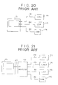
- Audio-visual systems generally have such a configuration as shown in FIG. 20 of the accompanying drawings.
- the audio-visual system includes an audio-visual monitor unit 171 and three audio-visual units including a video tape recorder (VTR) 173, a laser disk player (LDP) 175 and a video tape recorder 176 integrated with a camera (such video tape recorder will be hereinafter referred to as camcorder).
- VTR video tape recorder
- LDP laser disk player
- camcorder video tape recorder
- the video tape recorder 173 is connected to a first audio-visual terminal a of the audio-visual monitor unit 171 by way of an audio-visual cable 178; the laser disk player 175 is connected to a second audio-visual terminal b of the monitor unit 171 byway of another audio-visual cable 180; and the camcorder 176 is connected to a third audio-visual terminal c of the monitor unit 171 by way of a further audio-visual cable 181, so that video signals and audio signals of the video tape recorder 173, the laser disk player 175 and the camcorder 176 may be inputted to the monitor unit 171.
- the user when a broadcast of, for example, the sixth channel is to be received by means of a tuner of the video tape recorder 173 and displayed on the audio-visual monitor unit 171, the user will first manually operate a remote control unit (not shown) of the video tape recorder 173 to set the tuner of the video tape recorder 173 to the sixth channel. Then, the user will manually operate a remote control unit (not shown) of the monitor unit 171 to select the first audio-visual input terminal a of the monitor unit 171 while watching the screen of the monitor unit 171.
- a modified audio-visual system is also known and shown in FIG. 21.
- the audio-visual system shown is different from the audio-visual system shown in FIG. 20 in that it additionally includes an audio-visual (AV) selector 172.
- An output of the audio-visual selector 172 is connected, for example, to the first audio-visual input terminal a of the monitor unit 171 by way of an audio-visual cable 177.
- the audio-visual system further includes a tuner 174 as an additional audio-visual unit.
- the audio-visual units that is, the video tape recorder 173, the tuner 174, the laser disk player 175 and the camcorder 176, are connected to input terminals of the audio-visual selector 172 by way of audio-visual cables 178, 179, 180 and 181, respectively.
- One of the audio-visual units 173 to 176 is selected by the audio-visual selector 172, and a video signal and an audio signal of the selected audio-visual unit are inputted to the first audio-visual input terminal a of the monitor unit 17
- the audio-visual selector 172 when, for example, a reproduction program of the laser disk player 175 is to be displayed on the monitor unit 171, the audio-visual selector 172 will first be manually operated to set so that the output of the laser disk player 175 may be selected. Then, the remote control unit (not shown) of the monitor unit 171 will be manually operated to select the first audio-visual input terminal a while watching the screen of the monitor unit 171. Then, a remote control unit of the laser disk player 175 will be manually operated to set the laser disk player 175 to a reproduction mode.
- audio-visual systems have been developed wherein manually operable keys for controlling a plurality of audio-visual units are disposed on a housing of a single remote control unit or wherein a change-over switch for audio-visual units is provided so that one manually operable key is used commonly for a plurality of audio-visual units.
- the audio-visual system is difficult to use where it involves a large number of audio-visual units.
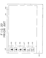
- FIG. 22 One of the control menu displaying apparatus is shown in FIG. 22.
- a control window 143 is displayed at a left end portion of a screen 141 of the television receiver, and icons 144 to 149 of a control menu for selecting a channel to be received are displayed in the control window 143. If one of the icons 144 to 149 is selected in this condition using a remote control unit or a pointing device such as a mouse not shown, then a program of the selected channel is received and an image is displayed in a major area 142 of the screen 141.
- control window 143 may be erased by manual operation of the remote control unit or the like to expand the area in which the image of the received program is displayed. It is to be noted that a further area 150 below the major area 142 and the control window 143 is used to display therein, for example, a displayed condition of the received channel in the form of a caption. Also the area 150 may be used to display part of the image of the received program therein.
- a monitor apparatus for an audio-visual system which includes a monitor unit, a plurality of audio-visual units, and audio-visual bus means for transmitting data signals including a command, a video signal and an audio signal between said monitor unit and said audio-visual units, comprising:
- the pointing means may include a plurality of remote control keys provided on a remote controller for the monitor unit.
- the monitor apparatus for an audio-visual system if the first control window displayed on the screen of the monitor unit is pointed using the pointing device to select one of the audio-visual units, then the second control window is displayed on the screen of the display unit, and accordingly, if the second control window is pointed using the pointing device, then an operation mode of the audio-visual unit selected in the first control window can be set. Accordingly, control of the entire audio-visual system can be performed by means of the single pointing device while the screen of the monitor unit is watched.
- an operation mode of the audio-visual unit selected using the pointing device can be set by means of any of the remote control keys. Accordingly, the user can control the audio-visual system simply without being aware of a source device under the plain concept that "what is observed can be moved".
- the pointing means may include indications of keys displayed in the second window.
- a monitor apparatus for an audio-visual system which includes a monitor unit, a first audio-visual unit having a receiving function, a second audio-visual unit having a reproducing function, and audio-visual bus means for transmitting data signals including a command, a video signal and an audio signal between the monitor unit and the first and second audio-visual units, which comprises display means, control window producing means for producing on the display means a control window in which a channel of a program received by the first audio-visual unit and supplied to the monitor unit and a designation of the second audio-visual unit for reproducing a program supplied to the monitor unit are displayed at a time, pointing means for pointing one of the channel and the designation displayed in the control window, and selecting means for selecting, in response to pointing by the pointing means, a program to be displayed on the display means.
- the pointing means may include a plurality of remote control keys provided on a remote controller for the monitor unit.
- a program to be displayed can be selected by pointing the reception channel or the second audio-visual unit in the control window displayed on the screen of the monitor unit using the pointing device.
- the selected program is supplied from the first audio-visual unit or the second audio-visual unit to the monitor unit by way of the audio-visual bus means.
- a monitor apparatus for an audio-visual system which receives and displays thereon various programs by way of a high speed large capacity digital communication network, which comprises display means, means for producing on the display means a control window in which a menu of the programs is displayed, pointing means for pointing one of the programs in the menu displayed in the control window, and controlling means for selecting the program pointed by the pointing means.
- a program to be displayed can be selected by pointing the menu in the control window displayed on the screen of the monitor unit using the pointing device.
- the selected program is supplied to the monitor unit by way of the high speed large capacity digital communication network. Accordingly, the monitorap- paratus is further enhanced in user interface.
- a control menu displaying apparatus for displaying a control menu for selecting a program to be displayed on a display unit, which comprises first means for causing the display unit to display thereon a control menu including several items of programs, second means for storing therein access data corresponding to the items, third means for developing an instruction to change the display position of a designated one of the items in the control menu, and fourth means responsive to the instruction from the third means for comparing the access data to the designated item with the access data to the other items and determining, based on a result of the comparison, whether or not the display position of the designated item should be changed.
- a control menu displaying apparatus for an audio-visual system, which includes a monitor unit, a plurality of audio-visual units, and audio-visual bus means for transmitting a command, a video signal and an audio signal between the monitor unit and the audio-visual units, for displaying a menu of programs supplied from the audio-visual units on the monitor unit, which comprises first means for causing the monitor unit to display thereon a control menu including several items of programs, second means for storing therein access data to the items, third means for developing an instruction to change the display position of a designated one of the items in the control menu, and fourth means responsive to the instruction from the third means for comparing the access data to the designated item with the access data to the other items and determining, based on a result of the comparison, whether or not the display position of the designated item should be changed.
- the display position of an arbitrary item in the menu can be changed in accordance with the accessing condition of the user. Consequently, the items in the menu can be displayed in order, for example, beginning with an item which is selected most frequently. Accordingly, those items which are accessed comparatively frequently will all be displayed at a time on the screen, and one of them can be selected without the necessity of manual operation for scrolling or the like. Consequently, the environment in which "a program enjoyed frequently can be selected immediately" is provided. Further, if a relationship between the frequency of access and time is taken and the display position of an item of the menu is determined forecasting a future frequency of access to the item, then a display of a menu which is further easy to use ran be provided.
- the audio-visual system shown includes an audio-visual monitor unit 21 with an audio-visual controlling function, which is connected to a video tape recorder (VTR) 22 via audio-visual buses 26a and 26b, further to a tuner (TUNER) 23 via audio-visual buses 27a and 27b, further to an laser disk player (LDP) 24 via audio-visual buses 28a and 28b and further to a camcorder (CAM) 25 via audio-visual buses 29a and 29b, thereby constituting a ring-like network.
- VTR video tape recorder
- TUNER tuner
- LDP laser disk player
- CAM camcorder
- data outputted, for example, from the audio-visual monitor unit 21 come to the video tape recorder 22 through the audio-visual bus 26a, to the tuner 23 further through the audio-visual bus 27a, to the laser disk player 24 further through the audio-visual bus 28a and to the camcorder 25 further through the audio-visual bus 29a.
- the data come to the laser disk player 24 fur- therthrough the audio-visual bus 29b, to the tuner23 further through the audio-visual bus 28b, to the video tape recorder 22 further through the audio-visual bus 27b, and back to the audio-visual monitor unit 21 further through the audio-visual bus 26b.
- the audio-visual buses 26a and 26b are accommodated in a single cable and constituted, for example, from optical fibres and have the transmission rate of 100 Mbits/sec.
- the audio-visual buses 27a and 27b, 28a and 28b, and 29a and 29b are constructed similarly to the audio-visual buses 26a and 26b.
- the signal format shown has the form of a packet including a control bit set and data (audio data, video data, a command and so forth).
- the control bit set includes a source address indicative of an audio-visual unit which has sent out the data, a destination address indicative of an audio-visual unit of the destination of the data, and so forth.
- the data in the signal format include a command for controlling an audio-visual unit such as the video tape recorder 22 or the tuner 23, an audio signal and/or a video signal sent out from the video tape recorder 22 or the tuner 23 to the audio-visual monitor unit21, and h, and have a length in accordance with contents of the data.
- an audio-visual unit such as the video tape recorder 22 or the tuner 23
- an audio signal and/or a video signal sent out from the video tape recorder 22 or the tuner 23 to the audio-visual monitor unit21 and h, and have a length in accordance with contents of the data.
- FIG. 7 the audio-visual monitor unit incorporated in the audio-visual system described hereinabove with reference to FIG. 5 is shown in block diagram.
- transmission lines only for a video signal and an audio signal are each indicated by a thick line.
- the audio-visual monitor unit shown includes an infrared-ray to electricity converter (IR/E) 31 which converts a command sent out as infrared-rays (IR) from a remote controlling and pointing device (which will be hereinafter described in detail) into an electric signal, and an interface (IF) 32 which transfers the electric signal to a control section 33.
- the control section 33 analyzes the command and sends it out to a display section 38.
- control section 33 adds, in accordance with contents of the command thus analyzed, a source address and a destination address to the data on which the command for controlling an audio-visual unit is carried, and sends out the resulted signal into the audio-visual bus 26a by way of an interface (IF) 34 and an electro-optic converter (E/O) 35.
- the control section 33 includes a CPU (central processing unit) 33a which analyzes a command inputted thereto and detects a program of which channel has been accessed.
- the CPU 33a stores a result of the detection into an access data memory 33d constituted from an EEPROM (electrically erasable programmable read only memory).
- the CPU 33a further executes necessary processing, which will be hereinafter described, in accordance with a control procedure or program stored in a ROM (read only memory) 33b.
- the control section 33 further includes a RAM (random access memory) 33c.
- a photoelectric converter 36 converts an optical signal inputted thereto from the audio-visual bus 26b into an electric signal and transfers it to the control section 33 by way of the interface 34.
- the data are a video signal or an audio signal sent out from an audio-visual unit, they are converted into an analog signal by a digital to analog converter (D/A) 37 and supplied to the display section 38.
- the display section 38 has an image display section and a sound display section, receives a video signal and an audio signal and displays them as an image and sound.
- FIG. 8 shows the construction of the laser disk player 24 of the audio-visual system described above. Also in FIG. 8, transmission lines only for a video signal and an audio signal are each indicated by a thick line similarly as in FIG. 7.
- the laser disk player 24 include a photoelectric converter (O/E) 41 which converts an optical signal inputted thereto through the audio-visual bus 28a into an electric signal, and an interface (IF) 45 which transfers the electric signal to a control section 46 which may be constituted from a microcomputer.
- the control section 46 fetches data inputted thereto by way of the interface 45 if the destination address added to the data is for the control section 46 itself, but if the destination address is not for the control section 46 itself, the control section 46 does not fetch the data.
- Data which have not been fetched by the control section 46 are converted into an optical signal by an electro-optic converter (E/O) 43 and are sent out into the audio-visual bus 29a.
- E/O electro-optic converter
- a reproducing section 47 reproduces a program from a laser disk based on the command analyzed by the control section 46.
- An analog to digital converter (A/D) 48 converts a video signal and an audio signal outputted from the reproducing section 47 into digital signals and sends them out to the interface 45.
- connection configurations of the video tape recorder 22, the tuner 23 and the camcorder 25 to the audio-visual buses are similar to that of the laser disk player 24 described above, and overlapping description thereof is omitted herein to avoid redundancy.
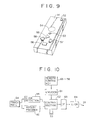
- the remote controlling and pointing device includes a remote controlling and pointing device housing 51 and several manually operable elements provided on the housing 51.
- the manually operable elements include a power source on/off switch 52 for the entire audio-visual system, a menu on/off switch 53 for setting the audio-visual monitor unit 21 of FIG. 5 to a condition wherein it displays a menu thereon, a click button/track ball 54, and remote control keys 55 to 58 for manually operating an audio-visual unit selected by the remote controlling and pointing device.
- a click detecting section 59 for detecting a click of the click button/track ball 54 and outputting it to a control section 62
- a rotary encoder 60 for detecting rotation of the click button/track ball 54 and outputting it to the control section 62
- an encoder 61 for detecting a manual operation of any of the remote control keys 55 to 58 and outputting it to the control section 62.
- the control section 62 receives a command of any of the remote control keys 55 to 58 inputted thereto by way of the encoder 61, a manual click operation inputted by way of the click detecting section 59 and rotation of the click button/track ball 54 inputted thereto by way of the rotary encoder 60 and outputs a command to an electricity to infrared-ray converter (E/IR) 64 by way of an interface (IF) 63 such as a drivercircuit.
- E/IR electricity to infrared-ray converter
- IF interface
- the command is outputted from the electricity to infrared-ray converter 64 to the audio-visual monitor unit 21 shown FIG. 5. It is to be noted that the power source on/off switch 52 for the entire system is omitted in (b) of FIG. 9.
- the monitor apparatus incorporated in the audio-visual system described above operates in the following manner. It is to be noted that operation of the monitor apparatus when the user wants to reproduce and display a program of the laser disk player 24 on the audio-visual monitor unit 21 will be described below by way of example.
- the user will turn on the power source on/off switch 52 of the remote controlling and pointing device.
- the control section 62 of the remote controlling and pointing device thus produces a command to turn on the power source of the audio-visual monitor unit 21, and the command is transmitted as an optical signal of infrared-rays from the electricity to infrared-ray converter 64 of the remote controlling and pointing device to the audio-visual monitor unit 21.
- control section 33 of the audio-visual monitor 21 first analyzes the command inputted thereto by way of the infrared-ray to electricity converter 31 and the interface 32 and performs initialization thereof including confirmation of connecting conditions of audio-visual units connected to the audio-visual buses, detection of an abnormal condition, and so forth (step S1 in FIG. 2).
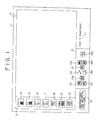
- the control section 33 of the audio-visual monitor unit 21 causes the display section 38 to display a first control window 3 on the left side of a major area 2 on a display screen 1 of the display section 38 and simultaneously causes the display section 38 to display icons 4 to 7 indicating receiving channels and icons 8 to 10 indicating the audio-visual units in the first control window 3.
- the control section 33 further causes the display section 38 to display a cursor (not shown) in the first control window 3.
- the icon 4 indicates reception of the first channel
- the icon 5 indicates reception of the sixth channel
- the icon 6 indicates reception of the first program of broadcasting via satellite
- the icon 7 indicates reception of the second program of broadcasting via satellite.
- the icon 8 indicates reproduction of a program of the video tape recorder 22
- the icon 9 indicates reproduction of a program of the laser disk player24
- the icon 10 indicates reproduction of a program of the camcorder 25.
- the user when the user wants to enjoy the broadcasting of t he first channel, the user should manually operate the click button/track ball 54 of the remote controlling and pointing device to move the cursor to the icon 4 and click it, but when the user wants to reproduce a program of the laser disk player 24, the user should similarly move the cursor to the icon 9 and click the click button/track ball 54.
- step S3 the user will manually operate the click button/track ball 54 of the remote controlling and pointing device to select the icon 9 and click it (step S3).
- the control section 33 of the audio-visual monitor unit 21 confirms that the laser disk player 24 has been selected (steps S4 and S5), it causes the colour of the background of the icon 9 to be changed to indicate that the laser disk player 24 has been selected and causes a second control window 12 to be displayed below the major area 2 of the screen 1 and further causes control keys 13a to 13j for setting an operation mode of the laser disk player 24 to be displayed in the second control window 12 as seen in FIG. 1 (step S6).
- the user will set the laser disk player 24 to a reproduction mode.
- Such setting may be achieved by manually operating the click button/track ball 54 to move the cursor to the PB control key 13a displayed at a lower portion of the second control window of the screen 1 and clicking it or by manually operating the PB remote control key 55 provided on the remote controlling and pointing device.
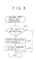
- the processing when the former manual operation is performed is executed at step S7, and the processing when the latter manual operation is performed is executed at step S8, and details of them are illustrated in FIGS. 3 and 4, respectively. In the following, a flow of operations of the processing when the former manual operation is performed will be described.
- step S71 when the cursor is moved to the PB control key 13a displayed on the audio-visual monitor unit 21 and the click button/track ball 54 is clicked, the control section 33 of the audio-visual monitor unit 21 judges whether or not the PB control key 13a displayed on the display section 38 has been operated. Then, if the judgment is YES, the control section 33 of the audio-visual monitor unit 21 confirms an audio-visual unit selected at present and recognizes that a control signal should be directed to the audio-visual unit, and here, the control section 33 processes determining that an instruction to reproduce the laser disk player 24 has been provided (step S72).
- control section 33 produces a command to set the laser disk player 24 to a reproduction mode, adds a control bit set indicating that the source address indicates the audio-visual monitor unit 21 and the destination address indicates the laser disk player 24, and sends out the resulted signal to the audio-visual bus 26a by way of the interface 34 and the electro-optical converter 35 (step S73), thereby completing the control key inputting processing.
- the control section 46 of the laser disk player 24 fetches, checking the destination address added to the data inputted thereto by way of the audio-visual bus 28a and the interface 45, the data and analyzes the command. Then, the control section 46 sets the reproducing section 47 to a reproduction mode to effect reproduction of a program. Further, the control section 46 adds, to a video signal and an audio signal outputted from the reproducing section 47 and converted into digital signals by the analog to digital converter 48, a control bit set which represents that the source address indicates the laser disk player 24 and the destination address indicates the audio-visual monitor unit 21, and sends out the resulted signal to the audio-visual bus 29a by way of the interface 45 and the electro-optical converter 43.
- the data sent out into the audio-visual bus 29a come to the audio-visual monitor unit 21 by way of the camcorder 25, the audio-visual bus 29b, the laserdisk player24, the audio-visual bus 28b, the tuner 23, the audio-visual bus 27b, the video tape recorder 22 and the audio-visual bus 26b.
- the control section 33 of the audio-visual monitor unit 21 fetches, checking the destination address added to the data inputted thereto from the audio-visual bus 26b, the data.
- the digital to analog converter 37 converts the data inputted thereto into an analog video signal and an analog audio signal and outputs them to the display section 38.
- the reproduction program of the laser disk player24 is displayed in the major area 2 of the screen 1, and a message 11 "Disk is displayed.” is displayed below the area 2 on the right side of the second control window 12. Further, another message 14 indicating "Preparations for recording and printing" is displayed on the left side of the second control window 12 (preparations for printing are made when a printer is connected to the audio-visual buses).
- the reproduction mode setting operation of the laser disk player 24 is completed with this. Since the various control keys (t he stop control key 13b, the fast feeding (FF) control key 13c, the rewinding (REW) control key 13d, the pause control key 13e, the high speed search control key 13f, the reverse high speed search control key 13g, the chapter control key 13h and the reverse chapter control key 13j) for controlling the laser disk player 24 are displayed on the screen 1 of the audio-visual monitor unit 21, the laser disk player 24 can be set to any operation mode by moving the cursor and clicking the click button/track ball 54.
- the various control keys t he stop control key 13b, the fast feeding (FF) control key 13c, the rewinding (REW) control key 13d, the pause control key 13e, the high speed search control key 13f, the reverse high speed search control key 13g, the chapter control key 13h and the reverse chapter control key 13j
- the flow of operations when the PB remote control key 55 provided on the remote controlling and pointing device is manually operated is similar to that of the case of FIG. 3, detailed description thereof is omitted herein.
- the four kinds of remote control keys including the PB remote control key 55, the stop remote control key 56, the fast feeding remote control key 57 and the rewinding remote control key 58 are provided on the remote controlling and pointing device, it is possible to set any of those operation modes.
- a signal generated by the encoder 61 when it detects a manual operation of any of the remote control keys 55 to 58 only designates an operation mode but does not designate an audio-visual unit.
- a monitor apparatus for an audio-visual system according to a second preferred embodiment of the present invention will be described.
- the monitor apparatus of the present embodiment is incorporated in the audio-visual system shown in FIG. 5 and has such hardware construction as shown in FIG. 7 similarly as in the first embodiment described hereinabove, and overlapping description of them is omitted herein to avoid redundancy.
- the monitor apparatus of the present embodiment is only different from the monitor apparatus of the preceding embodiment in that the control program stored in the ROM 33b of the control section 33 of the audio-visual monitor unit 21 is different and accordingly the monitor apparatus of the present embodiment operates in a different manner.
- operation of the monitor apparatus of the present embodiment will be described subsequently with reference to FIGS. 5 to 7 and 11 to 14.
- operation of the monitor apparatus when the user wants to display a control menu of the tuner 23 on the audio-visual monitor unit 21 will be described below by way of example.
- FIGS. 5, 7 and 14 the construction of the tuner 23 of the audio-visual system is shown. Also in FIG. 14, transmission lines only for a video signal and an audio signal are each indicated by a thick line similarly as in FIGS. 7 and 8.
- the tuner 23 includes a photoelectric converter (O/E) 71 which converts an optical signal inputted thereto through the audio-visual bus 27a into an electric signal, and an interface (IF) 75 which transfers the electric signal to a control section 76 which may be constituted from a microcomputer.
- the control section 76 fetches data inputted thereto by way of the interface 75 if the destination address added to the data is for the control section 76 itself, but if the destination address is not for the control section 76 itself, the control section 76 does not fetch the data.
- Data which have not been fetched by the control section 76 are converted into an optical signal by an electro-optic converter (E/O) 73 and are sent out into the audio-visual bus 28a.
- E/O electro-optic converter
- a receiving section 77 reproduces a program selected in accordance with the command analyzed by the control section 76.
- An analog to digital converter (A/D) 78 converts a video signal and an audio signal outputted from the reproducing section 77 into digital signals and sends them out to the interface 75.
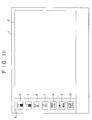
- the control section 33 of the audio-visual monitor unit 21 causes the display section 38 to display a first control window 3 on the display screen 1 of the display section 38 and simultaneously causes the display section 38 to display icons 4 to 7 indicating receiving channels and icons 8 to 10 indicating the audio-visual units in the first control window 3 as seen in FIG. 11, in a similar manner as shown in FIG. 11.
- the icons 4 to 10 are similarto those shown in FIG. 1 exceptthe icon 7, which indicates the second program of broadcasting via satellite received by means of the tuner 13.
- the control section 33 of the audio-visual monitor unit 21 thus analyzes the command inputted thereto by way of the infrared-ray to electricity converter 31 and the interface 32. Then, the control section 33 produces a command to set the receiving section 77 of the tuner 23 to the sixth channel and forward a signal of the received sixth channel to the audio-visual monitor unit 21, adds to the command a control bit set which represents that the source-address indicates the audio-visual monitor unit 21 and the destination address indicates the tuner 23, and sends out the resulted signal into the audio-visual bus 26a by way of the interface 34 and the electro-optic converter 35.
- the control section 76 of the tuner 23 fetches, checking the destination address added to the data inputted thereto by way of the audio-visual bus 27a and the interface 75, the data and analyzes the command. Then, the control section 76 sets the reproducing section 77 to the sixth channel to effect reception of the broadcasting. Further, the control section 76 adds, to a video signal and an audio signal received by the reproducing section 77 and converted into digital signals by the analog to digital converter 78, a control bit set which represents that the source address indicates the tuner 23 and the destination address indicates the audio-visual monitor unit 21, and sends out the resulted signal to the audio-visual bus 28a by way of the interface 75 and the electro-optical converter 73.
- the data sent out into the audio-visual bus 28a come to the audio-visual monitor unit 21 by way of the laser disk player 24, the audio-visual bus 29a, the camcorder 25, the audio-visual bus 29b, the laser disk player 24, the audio-visual bus 28b, the tuner 23, the audio-visual bus 27b, the video tape recorder 22 and the audio-visual bus 26b.
- the control section 33 of the audio-visual monitor unit 21 fetches, checking the destination address added to the data inputted thereto from the audio-visual bus 26b, the data.
- the digital to analog converter 37 converts the data inputted thereto into analog signals and outputs them to the display section 38. Consequently, the image of the sixth channel is displayed in the major area 2 of the screen 1.
- the display in the control window 3 may continue to be displayed, if the menu on/off switch 53 of the remote controlling and pointing device is turned off to erase it, then the area in which the image of the sixth channel is displayed can be increased.
- the area below the area 2 and the control window 3 is used to display, for example, a displayed condition of the received channel in a caption.
- the image of the program received may be displayed also in this area.
- the selecting operation of the sixth channel is completed with this. Subsequently, an operation of changing the display position of a control menu will be described.
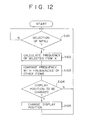
- the control section 33 of the audio-visual monitor unit 21 reads out data of access to the first channel stored in the access data memory 23d and calculates the frequency of accessing to it for a predetermined period of time (steps S101 and S102 shown in FIG. 12). Subsequently, the control section 33 calculates the accessing frequencies to the other items (here, the sixth channel and the first and second programs of broadcasting via satellite) (step S103).
- control section 33 compares the accessing frequencies thus calculated and judges whether or not the display position of the item indicative of reception of the first channel should be changed (step S104), and if itjudg- es that the display position should be changed, then it controls the display section 38 to change the display position of the item (step S105).
- the judgment whether or not the display position of the item should be changed may depend only upon the accessing frequency, if the relationship between the time and the accessing frequency is detected and the future accessing frequency is forecast using the relationship to make a judgment, then an item which is easier to use can be displayed.
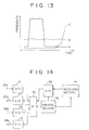
- the curve A shown in FIG. 13 indicates data of access to a seasonal program such as relay broadcasting of sports with respect to time. It can be seen that the accessing frequency is very high only within a particular time or season. Meanwhile, the curve B in FIG. 13 indicates data of access to a news program or the like and exhibits constant accessing. Further, the curve C in FIG. 13 indicates data of access, for example, to a drama which has been started last October, and it exhibits the tendency in which the accessing frequency has increased recently.
- the programs should be set such that the program of the news (for example, the first channel, which is watched constantly, is set to the uppermost position, and the dram (forexample, the sixth channel) is set to the second uppermost position while the sport program (for example, the fourth channel) which has not been watched recently is set to the third uppermost position.
- the control section 33 is provided with a learning function so that the item of a reception program or a reproduction program which is enjoyed periodically every week is shifted to the top or an upper position of the menu when the time comes, then the menu becomes further easy to use.
- the present invention is applied to an audio-visual system wherein an audio-visual monitor unit is connected to several audio-visual units by way of audio-visual buses which transmit a command signal, a video signal and an audio signal
- the present invention can also be applied to an audio-visual system wherein a command signal, a video signal and an audio signal are transmitted by way of separate cables or which consists of a television receiver by itself.
- access data memories may be provided individually in the control sections of the audio-visual units corresponding to items of programs so that access data may be stored in the access data memories (in particular, access data for a reception program are stored in the access data memory of the control section of the tuner, and access data for a reproduction program of the video tape recorder are stored in the access data memory of the control section of the video tape recorder) and selectively transferred to the audio-visual monitor unit by way of the audio-visual buses upon initial setting of a menu or upon instruction of changing of the menu position.
- a monitor apparatus for an audio-visual system according to a third preferred embodiment of the present invention will be described.
- the monitor apparatus of the present embodiment is incorporated in the audio-visual system shown in FIG. 5 and has such hardware construction as shown in FIG. 7 similarly as in the first and second embodiments described hereinabove, and overlapping description of them is omitted herein to avoid redundancy.
- the monitor apparatus of the present embodiment is only different from the monitor apparatus of the preceding embodiments in that the control program stored in the ROM 33b of the control section 33 of the audio-visual monitor unit 21 is different and accordingly the monitor apparatus of the present embodiment operates in a different manner.
- operation of the monitor apparatus of the present embodiment will be described subsequently with reference to FIGS. 5 to 7 and 15 to 17.
- operation of the monitor apparatus when the user wants to reproduce and display a program of the video tape recorder 22 on the audio-visual monitor unit 21 will be described below by way of example.
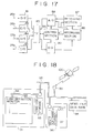
- FIGS. 5, 7 and 17 the construction of the video tape recorder 22 of the audio-visual system is shown. Also in FIG. 17, transmission lines only for a video signal and an audio signal are each indicated by a thick line similarly as in FIGS. 7, 8 and 14.
- the video tape recorder 22 includes a photoelectric converter (O/E) 81 which converts an optical signal inputted thereto through the audio-visual bus 25a into an electric signal, and an interface (IF) 85 which transfers the electric signal to a control section 86 which may be constituted from a microcomputer.
- the control section 86 fetches data inputted thereto by way of the interface 85 if the destination address added to the data is for the control section 86 itself, and analyzes and executes the command included in the data. But, if the destination address of the data inputted to the control section 86 is not for the control section 86 itself, the control section 86 does not fetch the data.
- Data which have not been fetched by the control section 86 are converted into an optical signal by an electro-optic converter (E/O) 83 and are sent out to the audio-visual bus 26a.
- a receiving section 87 receives television broadcasting of the predetermined channel based on the command analyzed by the control section 86, and a recording section 88 records or reproduces a television broadcasting signal received by the receiving section 87 based on the command analyzed by the control section 86 or a video signal and an audio signal of the laser disk player 23 or the camcorder 24 inputted thereto by way of the audio-visual bus 25a.
- An analog to digital (A/D) converter 89 converts a video signal and an audio signal outputted from the receiving section 87 or the recording section 88 into digital signals and sends them out to the interface 85.
- a digital to analog converter (D/A) 90 converts a video signal and an analog signal outputted from the camcorder 84 or any other audio-visual unit and inputted thereto from the audio-visual bus 25a into analog signals and sends them out to the recording section 88.
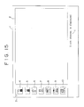
- the control section 33 of the audio-visual monitor unit 21 analyzes the command and causes the display section 38 to display a first control window 3 at the left end of the display screen 1 of the display section 38 and simultaneously causes the display section 38 to display icons 4 to 10 indicating different programs in the first control window 3 as seen in FIG. 15, in a similar manner as shown in FIGS. 1 and 11.
- the icons 4 to 10 are similar to those shown in FIG. 1.
- step S202 the user will manually operate the click button/track ball 54 of the remote controlling and pointing device to select the icon 5 and click it (step S202).
- the control section 33 of the audio-visual monitor unit 21 thus analyzes a command inputted thereto by way of the infrared-ray to electricity converter 31 and the interface 32.
- control section 33 produces a command to set the receiving section 87 of the video tape recorder 22 to the sixth channel and forward a signal of the received sixth channel to the audio-visual monitor unit 21, adds to the command a control bit set which represents that the source address indicates the audio-visual monitor unit 21 and the destination address indicates the video tape recorder 22, and sends out the resulted signal into the audio-visual bus 25a by way of the interface 34 and the electro-optic converter 35 (step S203).
- the control section 86 of the video tape recorder 22 fetches, checking the destination address added to the data inputted thereto, the data and analyzes the command. Then, the control section 86 sets the reproducing section 87 to the sixth channel to effect reception of the broadcasting (step S204).
- control section 86 adds, to reception signals converted into digital signals by the analog to digital converter 89, a control bit set which represents that the source address indicates the video tape recorder 22 and the destination address indicates the audio-visual monitor unit 21, and sends out the resulted signal into the audio-visual bus 27a by way of the interface 85 and the electro-optical converter 83 (step S205).
- the data sent out into the audio-visual bus 27a come to the audio-visual monitor unit 21 by way of the tuner 23, the audio-visual bus 28a, the laser disk player 24, the audio-visual bus 29a, the camcorder 25, the audio-visual bus 29b, the laser disk player 24, the audio-visual bus 28b, the tuner 23, the audio-visual bus 27b, the video tape recorder 22 and the audio-visual bus 26b.
- the control section 33 of the audio-visual monitor unit 21 fetches, checking the destination address added to the data inputted thereto from the audio-visual bus 26b, the data.
- the digital to analog converter 37 converts the data inputted thereto into analog signals and outputs them to the display section 38. Consequently, the image of the sixth channel is displayed in the major area 2 of the screen 1, and a message 11 "The sixth channel is displayed" is displayed in the area below the major area 2 (step S206). In this instance, while the icons 3 to 9 may continue to be displayed, if the menu on/off switch 53 of the remote controlling and pointing device is turned off to erase them, then the area in which the image of the sixth channel is displayed can be increased.
- the selecting operation of the sixth channel is completed with this (step S207).
- a plurality of video tape recorders may be provided in the present embodiment so that a broadcast received by an arbitrary one of them may be supplied to the audio-visual monitor unit 21. Further, the tuner 23 for exclusive use may be omitted.
- a printing apparatus such as a video printer, a unit which outputs only an audio signal such as a compact disk (CD) player and a digital audio tape player (DAT), and a multi-media unit such as a CD-I (compact disk interactive) player or a DVI player may be provided for the audio-visual buses.
- a printing apparatus such as a video printer, a unit which outputs only an audio signal such as a compact disk (CD) player and a digital audio tape player (DAT), and a multi-media unit such as a CD-I (compact disk interactive) player or a DVI player may be provided for the audio-visual buses.
- CD-I compact disk interactive
- FIG. 18 there is shown a different audio-visual system in which a monitor apparatus according to a fourth preferred embodiment of the present invention is incorporated.
- the audio-visual system shown includes a high definition monitor unit 92 and a home-use storage 93 installed in a home 94 in general and connected by way of a home audio-visual bus 94 to a high speed large capacity digital network 95 such as the B-ISDN.
- the home-use storage 93 is a storage device constituted from a hard disk drive unit or a magnetooptic disk drive unit and having the storage capacity of several gigabits and stores therein movie information inputted thereto from a movie software storage 97 of a movie distribution agency 96 or a news item inputted thereto from a news item data base of a newspaper company 98, or various programs of foreign countries inputted thereto from a communication satellite 100 by way of a satellite communication gateway 99, by way of the high speed large capacity digital communication network 95.
- the format of a signal passing the home audio-visual bus 94 may be the same as that in the audio-visual system of FIG. 5. Further, the connection configuration between the high definition monitor unit 92 and the home audio-visual bus 94 is similar to that of the audio-visual system of FIG. 5.
- FIG. 19 shows a menu display screen which may be used in the monitor apparatus of the present embodiment.
- the necessity for such selection of an audio-visual unit as in the preceding embodiments is eliminated, and the user is only required to select one of menu items 15 to 162 of programs displayed in a control window 152 at the left end of a display screen 151 separately for different categories such as a news, sport, a drama, ... and a program for children. Further, if an additional menu item 163 is selected, then a program is searched and selected in accordance with the title or the name of the director of a movie. Programs which are enjoyed comparatively frequently are displayed at upper portions of the menu display screen. Alternatively, a particular program (a news at seven o'clock) may be displayed at an upper portion of the menu display screen.
- a control section not shown in the high definition monitor unit 92 controls so that it either accesses the home-use storage 93 by way of the home audio-visual bus 94 or accesses the movie software storage 97 or the like by way of the high speed large capacity digital communication network 95 so that the selected program may be inputted to the high definition monitor unit 92.
- control window 156 is opened and control windows for "top ten", “movies in the 1990's” and so forth come out. If the "movies in the 1990's" is selected in this condition, then a control window in which several titles "XXX" of specific movies are displayed come out.
- the control section of the high definition monitor unit 92 first accesses to the home-use storage 93, and if the movie is not stored in the home-use storage 93, then the control section of the high definition monitor unit 92 accesses to the movie software storage 97 of the movie distribution agency 96.
- the control section causes the display screen 151 to display a message for selection whether the movie is to be enjoyed or copied or of cancellation.
- the movie is displayed in the region 152 of the display screen 151 of the high definition monitor unit 92 in accordance with contents thus selected and is stored into the home-use storage 93.
- the display returns to the screen of the control window in which the titles of the movies are displayed.
Landscapes
- Engineering & Computer Science (AREA)
- Signal Processing (AREA)
- Multimedia (AREA)
- Human Computer Interaction (AREA)
- Computer Networks & Wireless Communication (AREA)
- Selective Calling Equipment (AREA)
- Controls And Circuits For Display Device (AREA)
- Details Of Television Systems (AREA)
Applications Claiming Priority (2)
| Application Number | Priority Date | Filing Date | Title |
|---|---|---|---|
| JP86659/92 | 1992-03-11 | ||
| JP08665992A JP3198486B2 (ja) | 1992-03-11 | 1992-03-11 | Avシステムのモニタ装置 |
Publications (3)
| Publication Number | Publication Date |
|---|---|
| EP0560593A2 true EP0560593A2 (de) | 1993-09-15 |
| EP0560593A3 EP0560593A3 (en) | 1995-09-20 |
| EP0560593B1 EP0560593B1 (de) | 1999-05-12 |
Family
ID=13893166
Family Applications (1)
| Application Number | Title | Priority Date | Filing Date |
|---|---|---|---|
| EP93301823A Expired - Lifetime EP0560593B1 (de) | 1992-03-11 | 1993-03-10 | Gerät zum Anzeigen eines Kontrollmenüs |
Country Status (4)
| Country | Link |
|---|---|
| US (1) | US5371553A (de) |
| EP (1) | EP0560593B1 (de) |
| JP (1) | JP3198486B2 (de) |
| DE (1) | DE69324842T2 (de) |
Cited By (34)
| Publication number | Priority date | Publication date | Assignee | Title |
|---|---|---|---|---|
| EP0727909A3 (de) * | 1995-02-06 | 1997-07-23 | Sony Corp | Schnittstelle zwischen Audio-/Videoteilnehmereinrichtung und einer Fernmeldeleitung |
| EP0735749A3 (de) * | 1995-03-28 | 1997-09-17 | At & T Corp | Verfahren und Vorrichtung zum Finden und Auswählen eines gewünschten Datensatzes aus einem grossen Datensatzplan unter Verwendung eines Fernsehgerätes und eines einer TV-Fernbedienung ähnlichen Steuergerätes |
| FR2762114A1 (fr) * | 1997-03-18 | 1998-10-16 | Microsoft Corp | Interface-utilisateur/barre dediee aux canaux |
| EP0817479A3 (de) * | 1996-06-25 | 1998-12-16 | Sony Corporation | Videosystem-Steuerverfahren |
| EP0843468A3 (de) * | 1996-11-19 | 1998-12-23 | Sony Corporation | EPG-Anlage und deren Steuerungsverfahren |
| WO2000040013A1 (en) * | 1998-12-28 | 2000-07-06 | Thomson Licensing S.A. | System and method for customizing program guide information to include reminder item or local identifier |
| WO2001078383A3 (en) * | 2000-04-10 | 2002-02-21 | United Video Properties Inc | Interactive media guide with media guidance interface |
| EP1116630A3 (de) * | 1999-12-24 | 2003-11-26 | Siemens Aktiengesellschaft | Audio- und/oder Videosystem, insbesondere für Kraftfahrzeuge oder Heimanwendungen |
| EP1708498A2 (de) | 1994-05-20 | 2006-10-04 | United Video Properties Inc. | Verbessertes elektronisches Fernsehprogrammführungssystem und Verfahren |
| EP1410625A4 (de) * | 2001-02-20 | 2006-12-13 | Lg Electronics Inc | Einrichtung und verfahren zum anzeigen von pip auf tv |
| US7398541B2 (en) | 1993-09-09 | 2008-07-08 | United Video Properties, Inc. | Electronic television program guide schedule system and method |
| US7421724B2 (en) | 1996-05-03 | 2008-09-02 | Starsight Telecast Inc. | Systems and methods for displaying information regions in an interactive electronic program guide |
| US7487529B1 (en) | 1997-12-01 | 2009-02-03 | Starsight Telecast, Inc. | Electronic program guide system with advertising messages in pop-ups |
| US8266655B2 (en) | 1995-04-17 | 2012-09-11 | Starsight Telecast, Incorporated | Multi-source switching in a television system |
| EP2091228A4 (de) * | 2006-12-08 | 2012-12-19 | Panasonic Corp | Fernsteuerungssystem |
| US8613020B2 (en) | 1998-04-30 | 2013-12-17 | United Video Properties, Inc. | Program guide system with flip and browse advertisements |
| US8635649B2 (en) | 1996-12-19 | 2014-01-21 | Gemstar Development Corporation | System and method for modifying advertisement responsive to EPG information |
| US8931008B2 (en) | 1999-06-29 | 2015-01-06 | United Video Properties, Inc. | Promotional philosophy for a video-on-demand-related interactive display within an interactive television application |
| US8978064B2 (en) | 1998-09-22 | 2015-03-10 | Rovi Guides, Inc. | Interactive television program guide with passive content |
| US9113107B2 (en) | 2005-11-08 | 2015-08-18 | Rovi Guides, Inc. | Interactive advertising and program promotion in an interactive television system |
| US9591251B2 (en) | 1997-10-06 | 2017-03-07 | Rovi Guides, Inc. | Interactive television program guide system with operator showcase |
| US9635406B2 (en) | 1998-05-15 | 2017-04-25 | Rovi Guides, Inc. | Interactive television program guide system for determining user values for demographic categories |
| US9706245B2 (en) | 1998-07-17 | 2017-07-11 | Rovi Guides, Inc. | Interactive television program guide system having multiple devices within a household |
| US9736524B2 (en) | 2011-01-06 | 2017-08-15 | Veveo, Inc. | Methods of and systems for content search based on environment sampling |
| US9749693B2 (en) | 2006-03-24 | 2017-08-29 | Rovi Guides, Inc. | Interactive media guidance application with intelligent navigation and display features |
| US9848276B2 (en) | 2013-03-11 | 2017-12-19 | Rovi Guides, Inc. | Systems and methods for auto-configuring a user equipment device with content consumption material |
| US10015562B2 (en) | 2000-03-31 | 2018-07-03 | Rovi Guides, Inc. | System and method for metadata-linked advertisements |
| US10027998B2 (en) | 1998-07-14 | 2018-07-17 | Rovi Guides, Inc. | Systems and methods for multi-tuner recording |
| US10063934B2 (en) | 2008-11-25 | 2018-08-28 | Rovi Technologies Corporation | Reducing unicast session duration with restart TV |
| US10271088B2 (en) | 1998-07-17 | 2019-04-23 | Rovi Guides, Inc. | Interactive television program guide with remote access |
| US10694256B2 (en) | 2007-03-09 | 2020-06-23 | Rovi Technologies Corporation | Media content search results ranked by popularity |
| US10880607B2 (en) | 2003-11-06 | 2020-12-29 | Rovi Guides, Inc. | Systems and methods for providing program suggestions in an interactive television program guide |
| US10984037B2 (en) | 2006-03-06 | 2021-04-20 | Veveo, Inc. | Methods and systems for selecting and presenting content on a first system based on user preferences learned on a second system |
| US12120394B2 (en) | 2007-11-21 | 2024-10-15 | Rovi Guides, Inc. | Maintaining a user profile based on dynamic data |
Families Citing this family (98)
| Publication number | Priority date | Publication date | Assignee | Title |
|---|---|---|---|---|
| JPH03282676A (ja) * | 1990-03-30 | 1991-12-12 | Hitachi Ltd | 情報検索方法 |
| JPH0662464A (ja) * | 1992-08-10 | 1994-03-04 | Sony Corp | リモートコントロールシステム |
| EP0598516A3 (de) * | 1992-11-05 | 1996-07-03 | Sony Corp | Aufzeichnung und Wiedergabe von bewegten Bildern. |
| JPH06217250A (ja) * | 1993-01-20 | 1994-08-05 | Sony Corp | Av機器の信号ラインの制御方法 |
| JP3302425B2 (ja) * | 1993-01-29 | 2002-07-15 | パイオニア株式会社 | 選択方法及び選択装置 |
| CN1071977C (zh) | 1993-03-05 | 2001-09-26 | 杰姆斯达发展公司 | 使用压缩码作电视节目录像时间排定的装置与方法 |
| EP0626635B1 (de) | 1993-05-24 | 2003-03-05 | Sun Microsystems, Inc. | Graphische Benutzerschnittstelle mit Verfahren zur Schnittstellebildung mit fernsteuernden Einrichtungen |
| US6239794B1 (en) | 1994-08-31 | 2001-05-29 | E Guide, Inc. | Method and system for simultaneously displaying a television program and information about the program |
| US6064409A (en) * | 1993-09-22 | 2000-05-16 | National Instruments Corporation | System and method for providing audio probe and debugging features in a graphical data flow program |
| US8793738B2 (en) | 1994-05-04 | 2014-07-29 | Starsight Telecast Incorporated | Television system with downloadable features |
| US5589893A (en) * | 1994-12-01 | 1996-12-31 | Zenith Electronics Corporation | On-screen remote control of a television receiver |
| US5638061A (en) * | 1994-12-01 | 1997-06-10 | Zenith Electronics Corporation | Track ball mechanism and switch arrangement |
| US5880768A (en) | 1995-04-06 | 1999-03-09 | Prevue Networks, Inc. | Interactive program guide systems and processes |
| US5782548A (en) | 1995-04-07 | 1998-07-21 | Seiko Epson Corporation | Image projection system and a method of controlling a projected pointer |
| US6769128B1 (en) | 1995-06-07 | 2004-07-27 | United Video Properties, Inc. | Electronic television program guide schedule system and method with data feed access |
| US6359636B1 (en) | 1995-07-17 | 2002-03-19 | Gateway, Inc. | Graphical user interface for control of a home entertainment system |
| US5867223A (en) * | 1995-07-17 | 1999-02-02 | Gateway 2000, Inc. | System for assigning multichannel audio signals to independent wireless audio output devices |
| US5748254A (en) * | 1995-07-24 | 1998-05-05 | Coach Master International Corporation | Systems with a remote control in which information can be retrieved from an encoded, laser readable disc |
| US6323911B1 (en) | 1995-10-02 | 2001-11-27 | Starsight Telecast, Inc. | System and method for using television schedule information |
| US8850477B2 (en) | 1995-10-02 | 2014-09-30 | Starsight Telecast, Inc. | Systems and methods for linking television viewers with advertisers and broadcasters |
| US6732369B1 (en) | 1995-10-02 | 2004-05-04 | Starsight Telecast, Inc. | Systems and methods for contextually linking television program information |
| US5737028A (en) * | 1995-11-01 | 1998-04-07 | International Business Machines Corporation | Previous channel listing with cursor controlled user interface for television video displays |
| EP1284449A1 (de) * | 1996-01-29 | 2003-02-19 | Canon Kabushiki Kaisha | Digitalkamera und Rechner zur Verwendung damit |
| AU720866B2 (en) | 1996-03-15 | 2000-06-15 | Rovi Guides, Inc. | Combination of VCR index and EPG |
| JP3697317B2 (ja) | 1996-05-28 | 2005-09-21 | 株式会社東芝 | 通信装置 |
| JP3236227B2 (ja) * | 1996-09-18 | 2001-12-10 | キヤノン株式会社 | 編集機能内蔵再生装置 |
| US6687906B1 (en) | 1996-12-19 | 2004-02-03 | Index Systems, Inc. | EPG with advertising inserts |
| US6313880B1 (en) * | 1997-04-03 | 2001-11-06 | Sony Corporation | Display with one or more display windows and placement dependent cursor and function control |
| EP1036466B1 (de) | 1997-07-21 | 2003-03-26 | E Guide, Inc. | Verfahren zum navigieren in einem fernsehprogrammführer mit werbung |
| US7167763B2 (en) * | 1997-09-24 | 2007-01-23 | Sony Corporation | Method and apparatus for providing a graphical user interface for a player/recorder system |
| US7185355B1 (en) | 1998-03-04 | 2007-02-27 | United Video Properties, Inc. | Program guide system with preference profiles |
| KR100261111B1 (ko) * | 1998-05-06 | 2000-07-01 | 윤종용 | Ieee 1394 네트웍 시스템의 시스템 디바이스 동작 상태 표시 방법 |
| US6442755B1 (en) | 1998-07-07 | 2002-08-27 | United Video Properties, Inc. | Electronic program guide using markup language |
| US6505348B1 (en) | 1998-07-29 | 2003-01-07 | Starsight Telecast, Inc. | Multiple interactive electronic program guide system and methods |
| US6898762B2 (en) | 1998-08-21 | 2005-05-24 | United Video Properties, Inc. | Client-server electronic program guide |
| TW465235B (en) | 1998-09-17 | 2001-11-21 | United Video Properties Inc | Electronic program guide with digital storage |
| JP2000278654A (ja) * | 1999-03-26 | 2000-10-06 | Sony Corp | 音声及び/または映像信号の伝送システム、その送信装置、及びその受信装置 |
| KR20020031109A (ko) | 1999-06-28 | 2002-04-26 | 추후제출 | 전자 프로그램 가이드 데이터베이스를 사용하여 광고를수정하는 시스템 및 방법 |
| JP4660877B2 (ja) | 2000-01-11 | 2011-03-30 | ソニー株式会社 | 電子機器システム |
| GB0003306D0 (en) * | 2000-02-15 | 2000-04-05 | Koninkl Philips Electronics Nv | Control of interconnected audio/video devices |
| ES2312475T3 (es) | 2000-10-11 | 2009-03-01 | United Video Properties, Inc. | Sistemas y metodos para proporcionar el almacenamiento de datos en servidores de un sistema de entrega de medios bajo demanda. |
| US8255961B2 (en) | 2000-10-11 | 2012-08-28 | United Video Properties, Inc. | Systems and methods for caching data in media-on-demand systems |
| US7075586B2 (en) * | 2002-04-03 | 2006-07-11 | Thomson Licensing | Power-on detection of DVI receiver IC |
| US7225262B2 (en) * | 2002-06-28 | 2007-05-29 | Pitney Bowes Inc. | System and method for selecting an external user interface using spatial information |
| US6920557B2 (en) | 2002-06-28 | 2005-07-19 | Pitney Bowes Inc. | System and method for wireless user interface for business machines |
| KR100824380B1 (ko) * | 2002-08-08 | 2008-04-22 | 삼성전자주식회사 | 영상 기록/재생 장치 및 그 메뉴안내 표시방법 |
| US7356353B2 (en) * | 2002-10-10 | 2008-04-08 | Sony Corporation | Wireless communication device, wireless communication method, and wireless communication system |
| US7493646B2 (en) | 2003-01-30 | 2009-02-17 | United Video Properties, Inc. | Interactive television systems with digital video recording and adjustable reminders |
| JP4267525B2 (ja) * | 2004-06-14 | 2009-05-27 | アルパイン株式会社 | オーディオ再生装置及び音楽選曲方法 |
| US7873916B1 (en) * | 2004-06-22 | 2011-01-18 | Apple Inc. | Color labeling in a graphical user interface |
| US9213714B1 (en) * | 2004-06-22 | 2015-12-15 | Apple Inc. | Indicating hierarchy in a computer system with a graphical user interface |
| US8806533B1 (en) | 2004-10-08 | 2014-08-12 | United Video Properties, Inc. | System and method for using television information codes |
| JP4186943B2 (ja) * | 2005-03-25 | 2008-11-26 | 船井電機株式会社 | Av伝送システム |
| US8640166B1 (en) | 2005-05-06 | 2014-01-28 | Rovi Guides, Inc. | Systems and methods for content surfing |
| US8095951B1 (en) | 2005-05-06 | 2012-01-10 | Rovi Guides, Inc. | Systems and methods for providing a scan |
| KR100706507B1 (ko) * | 2005-06-02 | 2007-04-11 | 엘지전자 주식회사 | 디지털 비디오 녹화 및 재생 장치에서의 복수의 타이틀복사 방법 |
| KR100706506B1 (ko) * | 2005-06-02 | 2007-04-11 | 엘지전자 주식회사 | 디지털 비디오 녹화 및 재생 장치에서의 미디어 복사 장치및 방법 |
| KR100745264B1 (ko) * | 2005-06-02 | 2007-08-01 | 엘지전자 주식회사 | 디지털 비디오 녹화 및 재생 장치에서의 디스크 복사 방법 |
| US7788266B2 (en) | 2005-08-26 | 2010-08-31 | Veveo, Inc. | Method and system for processing ambiguous, multi-term search queries |
| EP1942657A4 (de) * | 2005-09-28 | 2009-11-11 | Panasonic Corp | Einrichtungssteuerverfahren mit einem operationsschirm und elektronische einrichtung und system mit dem verfahren |
| US20070156521A1 (en) | 2005-12-29 | 2007-07-05 | United Video Properties, Inc. | Systems and methods for commerce in media program related merchandise |
| JP4020162B1 (ja) * | 2006-07-27 | 2007-12-12 | オンキヨー株式会社 | 映像音声再生装置 |
| US8799954B1 (en) | 2006-07-31 | 2014-08-05 | Rovi Guides, Inc. | Systems and methods for providing custom media content flipping |
| US8832742B2 (en) | 2006-10-06 | 2014-09-09 | United Video Properties, Inc. | Systems and methods for acquiring, categorizing and delivering media in interactive media guidance applications |
| US8490138B2 (en) | 2007-02-23 | 2013-07-16 | Rovi Guides, Inc. | Channel searching by content type |
| US8418206B2 (en) | 2007-03-22 | 2013-04-09 | United Video Properties, Inc. | User defined rules for assigning destinations of content |
| US8407737B1 (en) | 2007-07-11 | 2013-03-26 | Rovi Guides, Inc. | Systems and methods for providing a scan transport bar |
| JP5020005B2 (ja) * | 2007-09-06 | 2012-09-05 | 三洋電機株式会社 | 放送信号受信装置 |
| JP5129533B2 (ja) * | 2007-09-07 | 2013-01-30 | キヤノン株式会社 | 放送受信装置、その制御方法 |
| US20090094555A1 (en) * | 2007-10-05 | 2009-04-09 | Nokia Corporation | Adaptive user interface elements on display devices |
| US20090109183A1 (en) * | 2007-10-30 | 2009-04-30 | Bose Corporation | Remote Control of a Display |
| JP2009118208A (ja) * | 2007-11-07 | 2009-05-28 | Hitachi Ltd | 表示装置 |
| US8601526B2 (en) | 2008-06-13 | 2013-12-03 | United Video Properties, Inc. | Systems and methods for displaying media content and media guidance information |
| JP5294955B2 (ja) * | 2009-04-08 | 2013-09-18 | キヤノン株式会社 | 映像処理装置及びその制御方法 |
| JP2009199617A (ja) * | 2009-05-07 | 2009-09-03 | Sony Corp | 情報処理装置および情報処理方法 |
| US8477960B2 (en) * | 2009-06-04 | 2013-07-02 | Wavrydr, L.L.C. | System for allowing selective listening on multiple televisions |
| US9166714B2 (en) | 2009-09-11 | 2015-10-20 | Veveo, Inc. | Method of and system for presenting enriched video viewing analytics |
| US8359616B2 (en) | 2009-09-30 | 2013-01-22 | United Video Properties, Inc. | Systems and methods for automatically generating advertisements using a media guidance application |
| USD687843S1 (en) | 2009-11-06 | 2013-08-13 | Bose Corporation | Audio/video device with graphical user interface |
| US8669949B2 (en) * | 2009-11-06 | 2014-03-11 | Bose Corporation | Touch-based user interface touch sensor power |
| US20110113371A1 (en) * | 2009-11-06 | 2011-05-12 | Robert Preston Parker | Touch-Based User Interface User Error Handling |
| US8686957B2 (en) * | 2009-11-06 | 2014-04-01 | Bose Corporation | Touch-based user interface conductive rings |
| US8350820B2 (en) * | 2009-11-06 | 2013-01-08 | Bose Corporation | Touch-based user interface user operation accuracy enhancement |
| US8601394B2 (en) * | 2009-11-06 | 2013-12-03 | Bose Corporation | Graphical user interface user customization |
| US9201584B2 (en) | 2009-11-06 | 2015-12-01 | Bose Corporation | Audio/visual device user interface with tactile feedback |
| US9354726B2 (en) * | 2009-11-06 | 2016-05-31 | Bose Corporation | Audio/visual device graphical user interface submenu |
| US20110113368A1 (en) * | 2009-11-06 | 2011-05-12 | Santiago Carvajal | Audio/Visual Device Graphical User Interface |
| US8692815B2 (en) * | 2009-11-06 | 2014-04-08 | Bose Corporation | Touch-based user interface user selection accuracy enhancement |
| US8638306B2 (en) * | 2009-11-06 | 2014-01-28 | Bose Corporation | Touch-based user interface corner conductive pad |
| US20110109560A1 (en) | 2009-11-06 | 2011-05-12 | Santiago Carvajal | Audio/Visual Device Touch-Based User Interface |
| US9204193B2 (en) | 2010-05-14 | 2015-12-01 | Rovi Guides, Inc. | Systems and methods for media detection and filtering using a parental control logging application |
| JP2012195628A (ja) * | 2011-03-14 | 2012-10-11 | Onkyo Corp | コンテンツ送受信システム |
| US8959452B2 (en) * | 2011-10-11 | 2015-02-17 | Texas Instruments Incorporated | Method, system and computer program product for receiving information from a user |
| US8805418B2 (en) | 2011-12-23 | 2014-08-12 | United Video Properties, Inc. | Methods and systems for performing actions based on location-based rules |
| US20140196062A1 (en) | 2013-01-10 | 2014-07-10 | United Video Properties, Inc. | Systems and methods for setting prices in data driven media placement |
| CN106325246A (zh) * | 2016-08-26 | 2017-01-11 | 曹蕊 | 一种集室内和远程控制的两用家庭影院系统及控制方法 |
| US11863927B2 (en) * | 2019-11-20 | 2024-01-02 | Bose Corporation | Audio device proximity detection |
| US11838597B1 (en) * | 2022-02-17 | 2023-12-05 | Verizon Patent And Licensing Inc. | Systems and methods for content discovery by automatic organization of collections or rails |
Family Cites Families (4)
| Publication number | Priority date | Publication date | Assignee | Title |
|---|---|---|---|---|
| JPS62208768A (ja) * | 1986-03-10 | 1987-09-14 | Matsushita Electric Ind Co Ltd | システム機器制御方式 |
| US5086385A (en) * | 1989-01-31 | 1992-02-04 | Custom Command Systems | Expandable home automation system |
| JPH078060B2 (ja) * | 1989-03-28 | 1995-01-30 | 松下電器産業株式会社 | リモコン操作型電子機器制御システム |
| IT1245038B (it) * | 1991-04-04 | 1994-09-13 | Sisvel Spa | Televisore con telecomando perfezionato |
-
1992
- 1992-03-11 JP JP08665992A patent/JP3198486B2/ja not_active Expired - Lifetime
-
1993
- 1993-03-10 DE DE69324842T patent/DE69324842T2/de not_active Expired - Lifetime
- 1993-03-10 EP EP93301823A patent/EP0560593B1/de not_active Expired - Lifetime
-
1994
- 1994-05-06 US US08/238,800 patent/US5371553A/en not_active Expired - Lifetime
Cited By (65)
| Publication number | Priority date | Publication date | Assignee | Title |
|---|---|---|---|---|
| US7398541B2 (en) | 1993-09-09 | 2008-07-08 | United Video Properties, Inc. | Electronic television program guide schedule system and method |
| EP2282534B1 (de) * | 1994-05-20 | 2013-06-26 | United Video Properties, Inc. | Verbessertes elektronisches Fernsehprogrammführungssystem und Verfahren |
| EP1708499A3 (de) * | 1994-05-20 | 2007-11-14 | United Video Properties Inc. | Verbessertes elektronisches Fernsehprogrammführungssytem und Verfahren |
| EP1708498A3 (de) * | 1994-05-20 | 2007-11-14 | United Video Properties Inc. | Verbessertes elektronisches Fernsehprogrammführungssystem und Verfahren |
| EP1708498A2 (de) | 1994-05-20 | 2006-10-04 | United Video Properties Inc. | Verbessertes elektronisches Fernsehprogrammführungssystem und Verfahren |
| EP2282533A1 (de) * | 1994-05-20 | 2011-02-09 | United Video Properties, Inc. | Verbessertes elektronisches Fernsehprogrammführungssystem und Verfahren |
| EP2282536A1 (de) * | 1994-05-20 | 2011-02-09 | United Video Properties, Inc. | Verbessertes elektronisches Fernsehprogrammführungssystem und Verfahren |
| US5905882A (en) * | 1995-02-06 | 1999-05-18 | Sony Corporation | Electronic-equipment control apparatus, electronic-equipment control method and electronic-equipment control system |
| EP0727909A3 (de) * | 1995-02-06 | 1997-07-23 | Sony Corp | Schnittstelle zwischen Audio-/Videoteilnehmereinrichtung und einer Fernmeldeleitung |
| US5912664A (en) * | 1995-03-28 | 1999-06-15 | Lucent Technologies Inc. | Program category selection with filtered data and displayed cascaded cards |
| EP0735749A3 (de) * | 1995-03-28 | 1997-09-17 | At & T Corp | Verfahren und Vorrichtung zum Finden und Auswählen eines gewünschten Datensatzes aus einem grossen Datensatzplan unter Verwendung eines Fernsehgerätes und eines einer TV-Fernbedienung ähnlichen Steuergerätes |
| US5812124A (en) * | 1995-03-28 | 1998-09-22 | Lucent Technologies, Inc. | Program category selection with filtered data and displayed cascaded cards |
| US8539528B2 (en) | 1995-04-17 | 2013-09-17 | Starsight Telecast, Inc. | Multi-source switching in a television system |
| US8640170B2 (en) | 1995-04-17 | 2014-01-28 | Starsight Telecast, Incorporated | Multi-source switching in a television system displaying source indicators |
| US8424040B2 (en) | 1995-04-17 | 2013-04-16 | Starsight Telecast, Incorporated | Multi-source switching in a television system |
| US8266655B2 (en) | 1995-04-17 | 2012-09-11 | Starsight Telecast, Incorporated | Multi-source switching in a television system |
| US7480929B2 (en) | 1996-05-03 | 2009-01-20 | Starsight Telecast, Inc. | Method and system for displaying advertisements in an electronic program guide |
| US7421724B2 (en) | 1996-05-03 | 2008-09-02 | Starsight Telecast Inc. | Systems and methods for displaying information regions in an interactive electronic program guide |
| US7552459B2 (en) | 1996-05-03 | 2009-06-23 | Starsight Telecast, Inc. | Information system |
| US7493641B2 (en) | 1996-05-03 | 2009-02-17 | Starsight Telecast, Inc. | Method and system for displaying advertisements in an electronic program guide |
| US8869204B2 (en) | 1996-05-03 | 2014-10-21 | Starsight Telecast, Inc. | Method and system for displaying advertisements in an electronic program guide |
| US8776125B2 (en) | 1996-05-03 | 2014-07-08 | Starsight Telecast Inc. | Method and system for displaying advertisements in an electronic program guide |
| EP0817479A3 (de) * | 1996-06-25 | 1998-12-16 | Sony Corporation | Videosystem-Steuerverfahren |
| EP0843468A3 (de) * | 1996-11-19 | 1998-12-23 | Sony Corporation | EPG-Anlage und deren Steuerungsverfahren |
| US5991832A (en) * | 1996-11-19 | 1999-11-23 | Sony Corporation | EPG apparatus and its control method |
| US8635649B2 (en) | 1996-12-19 | 2014-01-21 | Gemstar Development Corporation | System and method for modifying advertisement responsive to EPG information |
| GB2342241B (en) * | 1997-03-18 | 2001-08-22 | Microsoft Corp | Channel bar user interface for an entertainment system |
| FR2762114A1 (fr) * | 1997-03-18 | 1998-10-16 | Microsoft Corp | Interface-utilisateur/barre dediee aux canaux |
| GB2342241A (en) * | 1997-03-18 | 2000-04-05 | Microsoft Corp | Graphical user interface for TV channel selection with selection between full screen mode and windows mode |
| US6141003A (en) * | 1997-03-18 | 2000-10-31 | Microsoft Corporation | Channel bar user interface for an entertainment system |
| DE19811910B4 (de) | 1997-03-18 | 2018-05-03 | Rovi Technologies Corp. | Benutzer-Interface mit Kanalleiste für ein Unterhaltungssystem |
| GB2323489B (en) * | 1997-03-18 | 2001-08-22 | Microsoft Corp | Channel bar user interface for an entertainment system |
| GB2355873B (en) * | 1997-03-18 | 2001-08-22 | Microsoft Corp | Channel bar user interface for an entertainment system |
| GB2355873A (en) * | 1997-03-18 | 2001-05-02 | Microsoft Corp | Graphical user interface for TV channel selection with an icon for selection between a full screen mode and a windows mode |
| US9591251B2 (en) | 1997-10-06 | 2017-03-07 | Rovi Guides, Inc. | Interactive television program guide system with operator showcase |
| US7487529B1 (en) | 1997-12-01 | 2009-02-03 | Starsight Telecast, Inc. | Electronic program guide system with advertising messages in pop-ups |
| US8613020B2 (en) | 1998-04-30 | 2013-12-17 | United Video Properties, Inc. | Program guide system with flip and browse advertisements |
| US9635406B2 (en) | 1998-05-15 | 2017-04-25 | Rovi Guides, Inc. | Interactive television program guide system for determining user values for demographic categories |
| US10075746B2 (en) | 1998-07-14 | 2018-09-11 | Rovi Guides, Inc. | Client-server based interactive television guide with server recording |
| US10027998B2 (en) | 1998-07-14 | 2018-07-17 | Rovi Guides, Inc. | Systems and methods for multi-tuner recording |
| US9706245B2 (en) | 1998-07-17 | 2017-07-11 | Rovi Guides, Inc. | Interactive television program guide system having multiple devices within a household |
| US10271088B2 (en) | 1998-07-17 | 2019-04-23 | Rovi Guides, Inc. | Interactive television program guide with remote access |
| US8978064B2 (en) | 1998-09-22 | 2015-03-10 | Rovi Guides, Inc. | Interactive television program guide with passive content |
| WO2000040013A1 (en) * | 1998-12-28 | 2000-07-06 | Thomson Licensing S.A. | System and method for customizing program guide information to include reminder item or local identifier |
| AU767547B2 (en) * | 1998-12-28 | 2003-11-13 | Interdigital Madison Patent Holdings | System and method for customizing program guide information to include reminder item or local identifier |
| US6169543B1 (en) | 1998-12-28 | 2001-01-02 | Thomson Licensing S.A. | System and method for customizing program guide information to include reminder item or local identifier |
| US8931008B2 (en) | 1999-06-29 | 2015-01-06 | United Video Properties, Inc. | Promotional philosophy for a video-on-demand-related interactive display within an interactive television application |
| EP1116630A3 (de) * | 1999-12-24 | 2003-11-26 | Siemens Aktiengesellschaft | Audio- und/oder Videosystem, insbesondere für Kraftfahrzeuge oder Heimanwendungen |
| US10015562B2 (en) | 2000-03-31 | 2018-07-03 | Rovi Guides, Inc. | System and method for metadata-linked advertisements |
| WO2001078382A3 (en) * | 2000-04-10 | 2002-03-28 | United Video Properties Inc | Interactive television program guide systems with integrated program listings |
| WO2001078383A3 (en) * | 2000-04-10 | 2002-02-21 | United Video Properties Inc | Interactive media guide with media guidance interface |
| US7773156B2 (en) | 2001-02-20 | 2010-08-10 | Lg Electronics Inc. | Device and method for displaying PIP on TV |
| EP1410625A4 (de) * | 2001-02-20 | 2006-12-13 | Lg Electronics Inc | Einrichtung und verfahren zum anzeigen von pip auf tv |
| US10880607B2 (en) | 2003-11-06 | 2020-12-29 | Rovi Guides, Inc. | Systems and methods for providing program suggestions in an interactive television program guide |
| US10986407B2 (en) | 2003-11-06 | 2021-04-20 | Rovi Guides, Inc. | Systems and methods for providing program suggestions in an interactive television program guide |
| US9113107B2 (en) | 2005-11-08 | 2015-08-18 | Rovi Guides, Inc. | Interactive advertising and program promotion in an interactive television system |
| US10984037B2 (en) | 2006-03-06 | 2021-04-20 | Veveo, Inc. | Methods and systems for selecting and presenting content on a first system based on user preferences learned on a second system |
| US9749693B2 (en) | 2006-03-24 | 2017-08-29 | Rovi Guides, Inc. | Interactive media guidance application with intelligent navigation and display features |
| EP2091228A4 (de) * | 2006-12-08 | 2012-12-19 | Panasonic Corp | Fernsteuerungssystem |
| US10694256B2 (en) | 2007-03-09 | 2020-06-23 | Rovi Technologies Corporation | Media content search results ranked by popularity |
| US12120394B2 (en) | 2007-11-21 | 2024-10-15 | Rovi Guides, Inc. | Maintaining a user profile based on dynamic data |
| US10063934B2 (en) | 2008-11-25 | 2018-08-28 | Rovi Technologies Corporation | Reducing unicast session duration with restart TV |
| USRE50355E1 (en) | 2008-11-25 | 2025-03-25 | Adeia Technologies Inc. | Reducing unicast session duration with restart TV |
| US9736524B2 (en) | 2011-01-06 | 2017-08-15 | Veveo, Inc. | Methods of and systems for content search based on environment sampling |
| US9848276B2 (en) | 2013-03-11 | 2017-12-19 | Rovi Guides, Inc. | Systems and methods for auto-configuring a user equipment device with content consumption material |
Also Published As
| Publication number | Publication date |
|---|---|
| EP0560593A3 (en) | 1995-09-20 |
| EP0560593B1 (de) | 1999-05-12 |
| DE69324842D1 (de) | 1999-06-17 |
| US5371553A (en) | 1994-12-06 |
| JP3198486B2 (ja) | 2001-08-13 |
| JPH05260554A (ja) | 1993-10-08 |
| DE69324842T2 (de) | 1999-11-25 |
Similar Documents
| Publication | Publication Date | Title |
|---|---|---|
| US5371553A (en) | Monitor apparatus for selecting audio-visual units and operating modes from a control window | |
| JP3528480B2 (ja) | Epg機器及びその制御方法 | |
| KR101699902B1 (ko) | 디지털 저장 장치를 구비하는 전자 프로그램 가이드 | |
| US20100262912A1 (en) | Method of displaying recorded material and display device using the same | |
| KR20080094832A (ko) | 복수 채널 병렬 디지털 비디오 레코더 | |
| JP2773386B2 (ja) | モニタ・テレビジョン装置 | |
| KR101112186B1 (ko) | 네트워크 내의 디바이스와 연관된 컨텐츠 정보의 동적 디스플레이를 제공하기 위한 방법 및 장치 | |
| KR100395567B1 (ko) | 설정치를 공유하는 콤비네이션 시스템 및 콤비네이션시스템의 환경 설정방법 | |
| US20030095792A1 (en) | Information recording and playback apparatus | |
| JPH1188865A (ja) | 分散型ホームネットワーク | |
| JP2002185889A (ja) | コンテンツの検索・提示システム及び方法、並びに記憶媒体 | |
| US20030031456A1 (en) | Video recorder with improved control system | |
| JP3158388B2 (ja) | 表示制御装置 | |
| US20030223318A1 (en) | Digital contents playback apparatus | |
| US7136569B2 (en) | Combination system having a plurality of reproducing apparatuses and a method for controlling operation thereof | |
| US20050081236A1 (en) | Data processing apparatus, data processing method, recording medium and program | |
| KR100536839B1 (ko) | 복수 메뉴 디스플레이 영상 기록/재생 장치 및 그 표시방법 | |
| JPH05260556A (ja) | Avシステムのモニタ装置 | |
| JP2005223632A (ja) | 記録映像表示装置、記録映像表示方法及び記録映像表示システム | |
| GB2262419A (en) | Cable television receiving apparatus | |
| KR20000060084A (ko) | Tv 데이터 운용 장치 | |
| KR20030081869A (ko) | 하나의 오에스디 화면을 통해 각 장치의 제어가 가능한콤비네이션 시스템 및 그의 동작제어방법 | |
| JP2956079B2 (ja) | ディスプレイ装置 | |
| KR0147989B1 (ko) | 비디오 카세트 레코더의 검색 방법 | |
| KR0159410B1 (ko) | 컴퓨터를 이용한 비디오 카세트 레코더에서의 구간 재생 방법 |
Legal Events
| Date | Code | Title | Description |
|---|---|---|---|
| PUAI | Public reference made under article 153(3) epc to a published international application that has entered the european phase |
Free format text: ORIGINAL CODE: 0009012 |
|
| AK | Designated contracting states |
Kind code of ref document: A2 Designated state(s): DE GB NL |
|
| PUAL | Search report despatched |
Free format text: ORIGINAL CODE: 0009013 |
|
| AK | Designated contracting states |
Kind code of ref document: A3 Designated state(s): DE GB NL |
|
| 17P | Request for examination filed |
Effective date: 19960222 |
|
| 17Q | First examination report despatched |
Effective date: 19980115 |
|
| GRAG | Despatch of communication of intention to grant |
Free format text: ORIGINAL CODE: EPIDOS AGRA |
|
| GRAG | Despatch of communication of intention to grant |
Free format text: ORIGINAL CODE: EPIDOS AGRA |
|
| GRAH | Despatch of communication of intention to grant a patent |
Free format text: ORIGINAL CODE: EPIDOS IGRA |
|
| GRAH | Despatch of communication of intention to grant a patent |
Free format text: ORIGINAL CODE: EPIDOS IGRA |
|
| GRAA | (expected) grant |
Free format text: ORIGINAL CODE: 0009210 |
|
| AK | Designated contracting states |
Kind code of ref document: B1 Designated state(s): DE GB NL |
|
| REF | Corresponds to: |
Ref document number: 69324842 Country of ref document: DE Date of ref document: 19990617 |
|
| PLBE | No opposition filed within time limit |
Free format text: ORIGINAL CODE: 0009261 |
|
| STAA | Information on the status of an ep patent application or granted ep patent |
Free format text: STATUS: NO OPPOSITION FILED WITHIN TIME LIMIT |
|
| 26N | No opposition filed | ||
| REG | Reference to a national code |
Ref country code: GB Ref legal event code: IF02 |
|
| PGFP | Annual fee paid to national office [announced via postgrant information from national office to epo] |
Ref country code: DE Payment date: 20120323 Year of fee payment: 20 |
|
| PGFP | Annual fee paid to national office [announced via postgrant information from national office to epo] |
Ref country code: GB Payment date: 20120322 Year of fee payment: 20 |
|
| PGFP | Annual fee paid to national office [announced via postgrant information from national office to epo] |
Ref country code: NL Payment date: 20120327 Year of fee payment: 20 |
|
| REG | Reference to a national code |
Ref country code: DE Ref legal event code: R071 Ref document number: 69324842 Country of ref document: DE |
|
| REG | Reference to a national code |
Ref country code: NL Ref legal event code: V4 Effective date: 20130310 |
|
| REG | Reference to a national code |
Ref country code: GB Ref legal event code: PE20 Expiry date: 20130309 |
|
| PG25 | Lapsed in a contracting state [announced via postgrant information from national office to epo] |
Ref country code: DE Free format text: LAPSE BECAUSE OF EXPIRATION OF PROTECTION Effective date: 20130312 Ref country code: GB Free format text: LAPSE BECAUSE OF EXPIRATION OF PROTECTION Effective date: 20130309 |