EP0560616A1 - Système d'échappement - Google Patents
Système d'échappement Download PDFInfo
- Publication number
- EP0560616A1 EP0560616A1 EP93301877A EP93301877A EP0560616A1 EP 0560616 A1 EP0560616 A1 EP 0560616A1 EP 93301877 A EP93301877 A EP 93301877A EP 93301877 A EP93301877 A EP 93301877A EP 0560616 A1 EP0560616 A1 EP 0560616A1
- Authority
- EP
- European Patent Office
- Prior art keywords
- jacket
- vacuum
- passage
- space
- exhaust
- Prior art date
- Legal status (The legal status is an assumption and is not a legal conclusion. Google has not performed a legal analysis and makes no representation as to the accuracy of the status listed.)
- Withdrawn
Links
Images
Classifications
-
- F—MECHANICAL ENGINEERING; LIGHTING; HEATING; WEAPONS; BLASTING
- F01—MACHINES OR ENGINES IN GENERAL; ENGINE PLANTS IN GENERAL; STEAM ENGINES
- F01N—GAS-FLOW SILENCERS OR EXHAUST APPARATUS FOR MACHINES OR ENGINES IN GENERAL; GAS-FLOW SILENCERS OR EXHAUST APPARATUS FOR INTERNAL-COMBUSTION ENGINES
- F01N13/00—Exhaust or silencing apparatus characterised by constructional features
- F01N13/08—Other arrangements or adaptations of exhaust conduits
- F01N13/10—Other arrangements or adaptations of exhaust conduits of exhaust manifolds
- F01N13/102—Other arrangements or adaptations of exhaust conduits of exhaust manifolds having thermal insulation
-
- F—MECHANICAL ENGINEERING; LIGHTING; HEATING; WEAPONS; BLASTING
- F01—MACHINES OR ENGINES IN GENERAL; ENGINE PLANTS IN GENERAL; STEAM ENGINES
- F01N—GAS-FLOW SILENCERS OR EXHAUST APPARATUS FOR MACHINES OR ENGINES IN GENERAL; GAS-FLOW SILENCERS OR EXHAUST APPARATUS FOR INTERNAL-COMBUSTION ENGINES
- F01N13/00—Exhaust or silencing apparatus characterised by constructional features
- F01N13/14—Exhaust or silencing apparatus characterised by constructional features having thermal insulation
-
- F—MECHANICAL ENGINEERING; LIGHTING; HEATING; WEAPONS; BLASTING
- F01—MACHINES OR ENGINES IN GENERAL; ENGINE PLANTS IN GENERAL; STEAM ENGINES
- F01N—GAS-FLOW SILENCERS OR EXHAUST APPARATUS FOR MACHINES OR ENGINES IN GENERAL; GAS-FLOW SILENCERS OR EXHAUST APPARATUS FOR INTERNAL-COMBUSTION ENGINES
- F01N13/00—Exhaust or silencing apparatus characterised by constructional features
- F01N13/14—Exhaust or silencing apparatus characterised by constructional features having thermal insulation
- F01N13/141—Double-walled exhaust pipes or housings
- F01N13/146—Double-walled exhaust pipes or housings with vacuum in the space between both walls
-
- F—MECHANICAL ENGINEERING; LIGHTING; HEATING; WEAPONS; BLASTING
- F16—ENGINEERING ELEMENTS AND UNITS; GENERAL MEASURES FOR PRODUCING AND MAINTAINING EFFECTIVE FUNCTIONING OF MACHINES OR INSTALLATIONS; THERMAL INSULATION IN GENERAL
- F16L—PIPES; JOINTS OR FITTINGS FOR PIPES; SUPPORTS FOR PIPES, CABLES OR PROTECTIVE TUBING; MEANS FOR THERMAL INSULATION IN GENERAL
- F16L59/00—Thermal insulation in general
- F16L59/06—Arrangements using an air layer or vacuum
- F16L59/065—Arrangements using an air layer or vacuum using vacuum
Definitions
- This invention relates to a method of handling exhaust gases from an internal combustion engine, to an exhaust gas system for an internal combustion engine, as well as components therefor, and to a motor vehicle with such an exhaust system.
- catalytic convertors are widely fitted as part of the exhaust gas handling equipment, to convert noxious exhaust components into environmentally harmless components.
- Such converters only operate satisfactorily within a particular operating temperature range.
- a method of handling exhaust gases from an internal combustion engine wherein the gases are carried along a passage, and the passage is surrounded by a jacket characterised in that a vacuum is established within the jacket.
- the use of a vacuum jacket provides both thermal and sound insulation between the gases and the environment, and can assist in reducing noise propagation from the exhaust gas stream.
- the vacuum level in the jacket will equate with the maximum vacuum level in the intake manifold, eg about 80 kPa. It is however possible that the vacuum may decay, for example during prolonged motorway driving when the manifold vacuum may be at a lower level, eg about 50 kPa and a satisfactory effect will still be achieved at this level or even at lower levels.
- vacuum in this specification should therefore be construed to include any significantly sub-atmospheric pressure.
- the use of a vacuum jacket can help the catalyst to reach its operating temperature more quickly than would be the case without the thermal insulation provided by the jacket.
- vacuum may be supplied from the manifold to the jacket around the passage.
- the vacuum may be supplied to the jacket from an engine driven or an electrically driven vacuum pump.
- a check valve may be placed in the vacuum line leading from the intake manifold to the jacket, to allow air to be evacuated from the jacket but to prevent readmission of air to the jacket.
- an exhaust gas system for a motor vehicle in which a passage for exhaust gases leaving the engine is surrounded by a jacket, characterised in that a vacuum source is connected to the space between the jacket and the passage.
- the jacket preferably surrounds at least that part of the passage between the engine and the converter and the part of the passage containing the converter.
- the space between the jacket and the passage is preferably in communication with the engine intake manifold via a vacuum line so that the vacuum in the manifold is used to evacuate the space.
- a check valve is preferably fitted in the line to prevent readmission of air to the space.
- the invention also provides an exhaust pipe for a motor vehicle, the pipe comprising a central passage for exhaust gases surrounded by a jacket, the jacket defining a sealed space around the central passage, with an aperture communicating with the space and adapted to connect the space to a vacuum source.
- the invention can also be applied to an exhaust manifold and/or to an exhaust gas down pipe (being parts of an exhaust gas system), and accordingly the invention also provides an exhaust manifold and/or an exhaust gas down pipe comprising a central passage for exhaust gases surrounded by a jacket, the jacket defining a sealed space around the central passage, with an aperture communicating with the space and adapted to connect the space to a vacuum source.
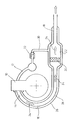
- an engine block 10 of an internal combustion engine has an intake manifold 12 and an exhaust manifold 14. Exhaust gases pass through the manifold 14, along a down pipe 16 and along an exhaust pipe 18. A catalyst brick 20 is fitted in a catalytic converter housing 22 such that the exhaust gases pass through the brick. The flow of exhaust gases is indicated by arrows 24.
- the exhaust gas passage consisting of the manifold 14, the down pipe 16 and the exhaust pipe 18 are all surrounded by a jacket 26 which defines a space 28 around the passage.
- the jacket is in the form of an outer tube surrounding the tube which forms the passage.
- the jacket will be correspondingly shaped so as to surround the walls of the passage to form a space 28 between the jacket and the passage which has a width of about 4 mm.
- the manifold 14, the downpipe 16 and the exhaust pipe 18 may be separate components joined to one another by appropriate flanges.
- each component may have its own, sealed jacket 26 or the jackets 26 around each component may communicate with one another to provide a single vacuum space.
- a vacuum line 30 links the space 28 with the intake manifold 12.
- a check valve 32 is fitted in this line.
- manifold vacuum is high (eg 80kPa), so that an equivalent vacuum can be drawn in the space 28.
- manifold vacuum drops (eg because the engine is heavily loaded), then the valve 32 closes to maintain the higher level of vacuum in the space.
- An additional advantage is that other components in the engine compartment will be shielded from the heat of the exhaust pipe.
Landscapes
- Engineering & Computer Science (AREA)
- General Engineering & Computer Science (AREA)
- Mechanical Engineering (AREA)
- Chemical & Material Sciences (AREA)
- Combustion & Propulsion (AREA)
- Exhaust Gas After Treatment (AREA)
- Exhaust Silencers (AREA)
Applications Claiming Priority (2)
| Application Number | Priority Date | Filing Date | Title |
|---|---|---|---|
| GB9205581 | 1992-03-13 | ||
| GB9205581A GB2265182A (en) | 1992-03-13 | 1992-03-13 | I.c.engine exhaust system |
Publications (1)
| Publication Number | Publication Date |
|---|---|
| EP0560616A1 true EP0560616A1 (fr) | 1993-09-15 |
Family
ID=10712127
Family Applications (1)
| Application Number | Title | Priority Date | Filing Date |
|---|---|---|---|
| EP93301877A Withdrawn EP0560616A1 (fr) | 1992-03-13 | 1993-03-12 | Système d'échappement |
Country Status (2)
| Country | Link |
|---|---|
| EP (1) | EP0560616A1 (fr) |
| GB (1) | GB2265182A (fr) |
Cited By (8)
| Publication number | Priority date | Publication date | Assignee | Title |
|---|---|---|---|---|
| DE19813590A1 (de) * | 1998-03-27 | 1999-09-30 | Audi Ag | Abgasbauteil für Brennkraftmaschinen |
| WO2002027161A1 (fr) * | 2000-08-18 | 2002-04-04 | Jefferson Liu | Pot d'echappement a isolation sonore et a protection contre les echaudures |
| DE102008051278A1 (de) | 2008-10-10 | 2010-04-29 | Audi Ag | Abgasanlage für Brennkraftmaschinen |
| EP2410149A2 (fr) | 2010-07-22 | 2012-01-25 | J. Eberspächer GmbH & Co. KG | Installation de gaz d'échappement |
| CN102748113A (zh) * | 2011-04-21 | 2012-10-24 | J·埃贝斯佩歇合资公司 | 排气系统组件 |
| FR2995352A1 (fr) * | 2012-09-13 | 2014-03-14 | Renault Sa | Vehicule automobile comprenant un moteur a combustion interne, un catalyseur et un dispositif d'isolation du catalyseur |
| JP2020029832A (ja) * | 2018-08-24 | 2020-02-27 | 株式会社豊田自動織機 | 内燃機関の吸排気構造 |
| FR3154765A1 (fr) * | 2023-10-30 | 2025-05-02 | Renault S.A.S. | Groupe motopropulseur et isolation du pot catalytique par dépression |
Citations (7)
| Publication number | Priority date | Publication date | Assignee | Title |
|---|---|---|---|---|
| CH302270A (fr) * | 1952-11-06 | 1954-10-15 | Grognuz Willy | Dispositif d'échappement silencieux pour moteur à combustion interne. |
| DE3238330A1 (de) * | 1982-10-15 | 1984-04-19 | Bayerische Motoren Werke AG, 8000 München | Abgassammler fuer brennkraftmaschinen |
| FR2573176A1 (fr) * | 1984-11-12 | 1986-05-16 | Marc Guerra | Procede pour l'isolation thermique |
| DE3537080C1 (en) * | 1985-10-18 | 1987-06-19 | Benteler Werke Ag | Exhaust pipe with built-in exhaust gas catalyst - and outer insulation coating contg. evacuated cavity with chamber filled with better alloy |
| FR2644207A1 (fr) * | 1989-03-07 | 1990-09-14 | Renault | Collecteur d'echappement pour moteur a combustion interne |
| JPH0454213A (ja) * | 1990-06-22 | 1992-02-21 | Calsonic Corp | 二重排気管装置 |
| JPH04187810A (ja) * | 1990-11-20 | 1992-07-06 | Calsonic Corp | 排気マニホールドの冷却保温装置 |
Family Cites Families (2)
| Publication number | Priority date | Publication date | Assignee | Title |
|---|---|---|---|---|
| JPS5335213B2 (fr) * | 1974-11-26 | 1978-09-26 | ||
| JPS5916085B2 (ja) * | 1976-05-18 | 1984-04-13 | トヨタ自動車株式会社 | 内燃機関用二重排気管の構造 |
-
1992
- 1992-03-13 GB GB9205581A patent/GB2265182A/en not_active Withdrawn
-
1993
- 1993-03-12 EP EP93301877A patent/EP0560616A1/fr not_active Withdrawn
Patent Citations (7)
| Publication number | Priority date | Publication date | Assignee | Title |
|---|---|---|---|---|
| CH302270A (fr) * | 1952-11-06 | 1954-10-15 | Grognuz Willy | Dispositif d'échappement silencieux pour moteur à combustion interne. |
| DE3238330A1 (de) * | 1982-10-15 | 1984-04-19 | Bayerische Motoren Werke AG, 8000 München | Abgassammler fuer brennkraftmaschinen |
| FR2573176A1 (fr) * | 1984-11-12 | 1986-05-16 | Marc Guerra | Procede pour l'isolation thermique |
| DE3537080C1 (en) * | 1985-10-18 | 1987-06-19 | Benteler Werke Ag | Exhaust pipe with built-in exhaust gas catalyst - and outer insulation coating contg. evacuated cavity with chamber filled with better alloy |
| FR2644207A1 (fr) * | 1989-03-07 | 1990-09-14 | Renault | Collecteur d'echappement pour moteur a combustion interne |
| JPH0454213A (ja) * | 1990-06-22 | 1992-02-21 | Calsonic Corp | 二重排気管装置 |
| JPH04187810A (ja) * | 1990-11-20 | 1992-07-06 | Calsonic Corp | 排気マニホールドの冷却保温装置 |
Non-Patent Citations (2)
| Title |
|---|
| PATENT ABSTRACTS OF JAPAN vol. 16, no. 242 (M-1259)3 June 1992 & JP-A-04 054213 ( CALSONIC CORP ) 21 February 1992 * |
| PATENT ABSTRACTS OF JAPAN vol. 16, no. 507 (M-1327)20 October 1992 & JP-A-04 187810 ( CALSONIC CORP ) 6 July 1992 * |
Cited By (17)
| Publication number | Priority date | Publication date | Assignee | Title |
|---|---|---|---|---|
| DE19813590B4 (de) * | 1998-03-27 | 2004-12-16 | Audi Ag | Abgasbauteil für Brennkraftmaschinen |
| DE19813590A1 (de) * | 1998-03-27 | 1999-09-30 | Audi Ag | Abgasbauteil für Brennkraftmaschinen |
| WO2002027161A1 (fr) * | 2000-08-18 | 2002-04-04 | Jefferson Liu | Pot d'echappement a isolation sonore et a protection contre les echaudures |
| GB2383608A (en) * | 2000-08-18 | 2003-07-02 | Jefferson Liu | An anti-scald exhaust muffler |
| DE102008051278A1 (de) | 2008-10-10 | 2010-04-29 | Audi Ag | Abgasanlage für Brennkraftmaschinen |
| DE102008051278B4 (de) * | 2008-10-10 | 2013-12-05 | Audi Ag | Verfahren zum Betreiben einer Abgasanlage sowie Abgasanlage für Brennkraftmaschinen |
| CN102345499B (zh) * | 2010-07-22 | 2014-07-23 | 埃贝赫有限两合公司 | 排气系统 |
| EP2410149A2 (fr) | 2010-07-22 | 2012-01-25 | J. Eberspächer GmbH & Co. KG | Installation de gaz d'échappement |
| DE102010031853A1 (de) | 2010-07-22 | 2012-01-26 | J. Eberspächer GmbH & Co. KG | Abgasanlage |
| CN102345499A (zh) * | 2010-07-22 | 2012-02-08 | 埃贝赫有限两合公司 | 排气系统 |
| US9587550B2 (en) | 2010-07-22 | 2017-03-07 | Eberspächer Exhaust Technology GmbH & Co. KG | Exhaust system |
| CN102748113A (zh) * | 2011-04-21 | 2012-10-24 | J·埃贝斯佩歇合资公司 | 排气系统组件 |
| CN102748113B (zh) * | 2011-04-21 | 2014-12-24 | J·埃贝斯佩歇合资公司 | 排气系统组件 |
| FR2995352A1 (fr) * | 2012-09-13 | 2014-03-14 | Renault Sa | Vehicule automobile comprenant un moteur a combustion interne, un catalyseur et un dispositif d'isolation du catalyseur |
| JP2020029832A (ja) * | 2018-08-24 | 2020-02-27 | 株式会社豊田自動織機 | 内燃機関の吸排気構造 |
| FR3154765A1 (fr) * | 2023-10-30 | 2025-05-02 | Renault S.A.S. | Groupe motopropulseur et isolation du pot catalytique par dépression |
| WO2025093549A1 (fr) * | 2023-10-30 | 2025-05-08 | Horse Powertrain Solutions, S.L.U | Groupe motopropulseur et isolation du pot catalytique par dépression |
Also Published As
| Publication number | Publication date |
|---|---|
| GB2265182A (en) | 1993-09-22 |
| GB9205581D0 (en) | 1992-04-29 |
Similar Documents
| Publication | Publication Date | Title |
|---|---|---|
| EP0530017B1 (fr) | Silencieux convertisseur catalytique combiné | |
| US6457462B2 (en) | Combined crankcase and canister ventilation system | |
| US5603295A (en) | Internal-combustion engine comprising an intake system | |
| CA2063934C (fr) | Circuit d'echappement pour moteur a combustion interne a cylindres en v, a convertisseur catalytique | |
| SE9602506L (sv) | Katalytiskt ljuddämpningssystem | |
| JP2003020925A (ja) | エンジン用クランク室ポジティブ換気サブアセンブリ及びその熱管理のための装置 | |
| EP0560616A1 (fr) | Système d'échappement | |
| US4172508A (en) | Exhaust silencers | |
| JPH07205890A (ja) | 船の推進装置 | |
| KR100537296B1 (ko) | 엔진의 배기가스 정화장치 | |
| EP1288603A3 (fr) | Echangeur de chaleur pour gaz d'échappement | |
| US3851470A (en) | Anti-pollution exhaust conversion systems | |
| US3691772A (en) | Exhaust gas cleansing system | |
| JP2000257418A (ja) | 排気消音装置 | |
| GB2111122A (en) | Silencer arrangement at the inlet of an I.C. engine air cleaner | |
| KR20010023404A (ko) | 가스-동압력 파형기 | |
| US5549872A (en) | Apparatus for purifying engine exhaust gas | |
| SE9303843D0 (sv) | Ljuddämpare för förbränningsmotor | |
| JPH08240158A (ja) | Egr装置 | |
| US3943711A (en) | Multi-stage air pump for supplying secondary air into an exhaust gas purification system | |
| KR100340104B1 (ko) | 엔진의 아이들 구동시의 저주파 부밍소음 저감을 위한머플러장치 | |
| JP2001241323A (ja) | 内燃機関の排気ガスの排出処理装置 | |
| KR100293541B1 (ko) | 흡기량조절장치 | |
| KR100290023B1 (ko) | 자동차용 머플러 | |
| JPS6157491A (ja) | 船外機の消音器 |
Legal Events
| Date | Code | Title | Description |
|---|---|---|---|
| PUAI | Public reference made under article 153(3) epc to a published international application that has entered the european phase |
Free format text: ORIGINAL CODE: 0009012 |
|
| AK | Designated contracting states |
Kind code of ref document: A1 Designated state(s): DE FR GB |
|
| STAA | Information on the status of an ep patent application or granted ep patent |
Free format text: STATUS: THE APPLICATION IS DEEMED TO BE WITHDRAWN |
|
| 18D | Application deemed to be withdrawn |
Effective date: 19951003 |