EP0560643A1 - Verfahren und Vorrichtung zur Hochdruck-IMC-Beschichtung - Google Patents
Verfahren und Vorrichtung zur Hochdruck-IMC-Beschichtung Download PDFInfo
- Publication number
- EP0560643A1 EP0560643A1 EP93400403A EP93400403A EP0560643A1 EP 0560643 A1 EP0560643 A1 EP 0560643A1 EP 93400403 A EP93400403 A EP 93400403A EP 93400403 A EP93400403 A EP 93400403A EP 0560643 A1 EP0560643 A1 EP 0560643A1
- Authority
- EP
- European Patent Office
- Prior art keywords
- chamber
- injection
- piston
- pressure
- injection pipe
- Prior art date
- Legal status (The legal status is an assumption and is not a legal conclusion. Google has not performed a legal analysis and makes no representation as to the accuracy of the status listed.)
- Granted
Links
- 239000011248 coating agent Substances 0.000 title claims abstract description 43
- 238000000576 coating method Methods 0.000 title claims abstract description 43
- 238000000034 method Methods 0.000 title claims description 27
- 238000002347 injection Methods 0.000 claims abstract description 83
- 239000007924 injection Substances 0.000 claims abstract description 83
- 239000000463 material Substances 0.000 claims abstract description 47
- 238000006073 displacement reaction Methods 0.000 claims abstract description 7
- 239000000203 mixture Substances 0.000 claims description 7
- 230000000149 penetrating effect Effects 0.000 claims description 6
- 239000000314 lubricant Substances 0.000 claims description 3
- 238000005086 pumping Methods 0.000 claims description 3
- 238000007789 sealing Methods 0.000 claims description 2
- 238000010438 heat treatment Methods 0.000 description 2
- 238000009434 installation Methods 0.000 description 2
- 239000002987 primer (paints) Substances 0.000 description 2
- 239000005002 finish coating Substances 0.000 description 1
- 239000008240 homogeneous mixture Substances 0.000 description 1
- 238000011065 in-situ storage Methods 0.000 description 1
- 239000011872 intimate mixture Substances 0.000 description 1
- 238000012986 modification Methods 0.000 description 1
- 230000004048 modification Effects 0.000 description 1
- 239000003973 paint Substances 0.000 description 1
- 230000035515 penetration Effects 0.000 description 1
- 239000013615 primer Substances 0.000 description 1
- 238000010992 reflux Methods 0.000 description 1
- 239000000126 substance Substances 0.000 description 1
- 229920001187 thermosetting polymer Polymers 0.000 description 1
- 238000011144 upstream manufacturing Methods 0.000 description 1
- 238000005303 weighing Methods 0.000 description 1
Images


Classifications
-
- B—PERFORMING OPERATIONS; TRANSPORTING
- B29—WORKING OF PLASTICS; WORKING OF SUBSTANCES IN A PLASTIC STATE IN GENERAL
- B29C—SHAPING OR JOINING OF PLASTICS; SHAPING OF MATERIAL IN A PLASTIC STATE, NOT OTHERWISE PROVIDED FOR; AFTER-TREATMENT OF THE SHAPED PRODUCTS, e.g. REPAIRING
- B29C45/00—Injection moulding, i.e. forcing the required volume of moulding material through a nozzle into a closed mould; Apparatus therefor
- B29C45/16—Making multilayered or multicoloured articles
- B29C45/1679—Making multilayered or multicoloured articles applying surface layers onto injection-moulded substrates inside the mould cavity, e.g. in-mould coating [IMC]
-
- B—PERFORMING OPERATIONS; TRANSPORTING
- B29—WORKING OF PLASTICS; WORKING OF SUBSTANCES IN A PLASTIC STATE IN GENERAL
- B29C—SHAPING OR JOINING OF PLASTICS; SHAPING OF MATERIAL IN A PLASTIC STATE, NOT OTHERWISE PROVIDED FOR; AFTER-TREATMENT OF THE SHAPED PRODUCTS, e.g. REPAIRING
- B29C37/00—Component parts, details, accessories or auxiliary operations, not covered by group B29C33/00 or B29C35/00
- B29C37/0025—Applying surface layers, e.g. coatings, decorative layers, printed layers, to articles during shaping, e.g. in-mould printing
- B29C37/0028—In-mould coating, e.g. by introducing the coating material into the mould after forming the article
-
- B—PERFORMING OPERATIONS; TRANSPORTING
- B29—WORKING OF PLASTICS; WORKING OF SUBSTANCES IN A PLASTIC STATE IN GENERAL
- B29C—SHAPING OR JOINING OF PLASTICS; SHAPING OF MATERIAL IN A PLASTIC STATE, NOT OTHERWISE PROVIDED FOR; AFTER-TREATMENT OF THE SHAPED PRODUCTS, e.g. REPAIRING
- B29C45/00—Injection moulding, i.e. forcing the required volume of moulding material through a nozzle into a closed mould; Apparatus therefor
- B29C45/02—Transfer moulding, i.e. transferring the required volume of moulding material by a plunger from a "shot" cavity into a mould cavity
- B29C2045/025—Transfer moulding, i.e. transferring the required volume of moulding material by a plunger from a "shot" cavity into a mould cavity with the transfer plunger surface forming a part of the mould cavity wall at the end of the plunger transfer movement
-
- B—PERFORMING OPERATIONS; TRANSPORTING
- B29—WORKING OF PLASTICS; WORKING OF SUBSTANCES IN A PLASTIC STATE IN GENERAL
- B29C—SHAPING OR JOINING OF PLASTICS; SHAPING OF MATERIAL IN A PLASTIC STATE, NOT OTHERWISE PROVIDED FOR; AFTER-TREATMENT OF THE SHAPED PRODUCTS, e.g. REPAIRING
- B29C67/00—Shaping techniques not covered by groups B29C39/00 - B29C65/00, B29C70/00 or B29C73/00
- B29C67/24—Shaping techniques not covered by groups B29C39/00 - B29C65/00, B29C70/00 or B29C73/00 characterised by the choice of material
- B29C67/246—Moulding high reactive monomers or prepolymers, e.g. by reaction injection moulding [RIM], liquid injection moulding [LIM]
Definitions
- the present invention relates to a method for penetrating a coating material under high pressure inside a mold, as well as to a device which can be used for carrying out this method.
- the invention applies more particularly to a primer or finish coating formed in situ on a molded part, that is to say inside its mold and before removing the elements from the mold and d 'extract the part.
- a method for forming a coating is described in US-A-4 668 460.
- High pressure hundredseveral hundred bars
- the material enters the mold through a cylindrical chamber in which slides a rod forming a shutter. When the rod is retracted, the chamber communicates with an injection circuit comprising pumps delivering the material at the desired high pressure.
- a drawback of this technique is that, unless the usable pressures are limited, the chamber and the injection circuit must be given a very robust and therefore expensive structure.
- US-A-4 668 460 indicates that the above technique can be used to apply a coating material consisting of a mixture of two or more reactive components.
- the premixed components are injected via the same injection circuit.
- a main object of the present invention is to provide a method and a device which overcomes the above drawbacks and which allows the use of high pressures to penetrate the coating material into the mold without significantly increasing the complexity or the cost of equipment.
- Another object of the invention is that the method can be applied in a simple manner in the case of a coating material obtained from several components.
- the chamber and the piston need to be designed to withstand the second pressure applied to make the material penetrate the mold. Upstream of the chamber, the pressures exerted are lower and the corresponding equipment can therefore be simpler and more economical. In addition, by reducing the number of zones exposed to the highest pressure, the safety conditions in the vicinity of the installation are improved.
- the two components are mixed during the injection step by converging several streams containing the components respectively under said first press.
- the simultaneous mixing and injection of the components allows the process to be carried out in a relatively short time.
- the first pressure can then be adjusted to obtain a homogeneous mixture of the reactive components under optimal conditions, while the second pressure is determined to obtain the best distribution of the material in the mold after mixing.
- the second aspect of the invention relates to a device for penetrating a coating material under high pressure inside a mold, comprising a chamber having one end open towards the inside of the mold and injection means for injecting the coating material in the chamber, these injection means including an injection conduit opening into the chamber, characterized in that it further comprises a piston movable in the chamber between a first position in which the piston closes the open end of the chamber and a second position beyond the injection pipe relative to the open end of the chamber, in that the injection means are adapted to inject the coating material into the chamber under a first pressure , and in that means for actuating the piston are provided for moving the piston in the direction going from said second position to said first position with a corresponding force.
- ndant inside the chamber, at a second pressure on prior to said first pressure.
- This device is designed for implementing the method described above.
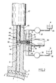
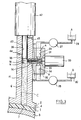
- FIGS. 1 to 4 are schematic sectional views of a device according to the invention, shown at different stages of the method according to the invention.
- the device shown in Figures 1 to 4 is used to penetrate a coating material inside a mold 2, 3 in which a part 1 has been previously formed.
- the mold consists of two elements 2, 3 defining between them a cavity.
- the thermosetting material of the part to be molded is placed in the mold cavity, the mold elements 2, 3 are pressed towards each other to put in place forms the part 1, then a known heat treatment is applied to the part 1 to make it harden at least partially and to make its surface 4 receptive to the coating to be applied.
- the coating is applied to the part 1 by causing the coating material to penetrate under high pressure (typically several hundred bars) inside the mold and without first removing the elements from mold 2, 3. This operation is carried out by implementing the present invention.
- the coating material used for example intended to form a primer or paint layer on a bodywork part, can be constituted by a single substance or by a mixture of several reactive components.
- the coating material C consists of a mixture of two components A, B.
- the device according to the invention comprises a chamber 6 which in the example shown, is constituted by a cylindrical channel of axis D formed in the upper mold element 2.
- the chamber 6 has a lower end 7 open towards the cavity formed inside the mold.
- the device according to the invention comprises injection means, indicated overall by the reference 13 in FIG. 1, for injecting the coating material into the chamber 6.
- injection means 13 comprise a cylindrical injection pipe 14 , transverse to the axis D of the chamber, having one end 16 open towards the interior of the chamber 6.
- the injection duct 14 is formed in a cylindrical part 17, the front part of which is installed in a sealed manner in an opening 18 formed in the wall 11 of the chamber 6. Behind the wall 11, this cylindrical part 17 has two diametrically opposite orifices 21, 22 which open into the injection pipe 14.
- each orifice 21, 22 communicates with a respective cavity 23, 24 formed in an element 26.
- the element 26 is mounted in leaktight manner around the rear part of the cylindrical part 17, and fixed by means s not shown on the wall 11 of the chamber 6.
- the injection means 13 further comprise pumping means comprising, for each component A, B of the coating material, a metering pump 27, 28 whose inlet is connected to a reservoir 29, 30 of said component, and whose outlet is connected to a respective cavity 23, 24 of the element 26 and to the corresponding orifice 21, 22.
- the metering pumps used 27, 28 are adapted to deliver each component A, B through the corresponding orifice 21, 22 under a first predetermined pressure PO.
- the pressure PO is for example of the order of 15 MPa (150 bars).
- the injection means 13 also comprise means for closing the injection pipe, comprising a needle 32 sliding in the injection pipe 14 and an actuator such as a hydraulic cylinder 33 connected to the needle 32.
- the needle 32 is mounted in conduit 14 with a substantially zero clearance so as to produce a seal by simple contact between the periphery of needle 32 and the wall of conduit 14.
- the needle 32 is movable in the injection pipe 14 between a closed position in which it closes both the end 16 of the pipe 14 open towards the chamber 6 and the two orifices 21, 22 ( Figures 1, 3 and 4), and a retraction position beyond the orifices 21, 22 relative to the open end 16 (FIG. 2).
- the jack 33 is chosen so that it can control the movement of the needle 32 in both directions between these two positions with a force F1 sufficient to overcome the pressure PO exerted at the orifices 21,22.
- a cylindrical piston 38 is slidably mounted parallel to the axis D in the chamber 6.
- the chamber 6 is arranged.
- the chamber 6 and the piston 38 are arranged so that the direction D of sliding of the piston is substantially vertical, with the end 7 of chamber 6 directed downwards.
- the piston 38 has an external cross section substantially identical to the internal cross section of the chamber 6. There is only a clearance of the order of 1 or 2 microns between the periphery 39 of the piston 38 and the wall 11 of chamber 6, which enables sealing by simple contact around the piston 38 movable in chamber 6.
- the piston 38 is movable in the chamber between a first position in which it closes the end 7 of the chamber 6 open towards the inside of the mold (lower position shown in Figures 1 and 4), and a second position beyond the injection duct 14 relative to the open end 7 of the chamber (upper retracted position shown in Figures 2 and 3).
- Actuating means such as a hydraulic cylinder 42 are connected to the piston 38 to control the movement of the piston 38 in both directions between these two positions.
- This second pressure P2 is greater than the first pressure PO under which the components A, B are injected into chamber 6.
- the second pressure P2 is for example of the order of 70 MPa (700 bars).
- the chamber 6 is extended by a section of coaxial cylindrical channel 43 having substantially the same interior cross-section as the chamber 6.
- a clearance slightly greater than that existing between the wall of the chamber 6 and the periphery 39 of the piston which allows applying a lubricant against the periphery 39 of the piston to promote its sliding in the channel composed of the section 43 and of the chamber 6.
- orifices 44, 45 are formed in the wall of the section of channel 43 to make circulate a lubricant on the periphery 39 of the piston 38, as schematically indicated by the arrows G, H in FIG. 1.
- the device When the part 1 has been shaped in the mold 1 and when the heat treatment ends, the device is in the state shown in FIG. 1.
- the piston 38 is in its lower position and the needle 32 in its closed position.
- the cylinder 42 is then controlled so that it displaces the piston 38 to its upper position, which creates a vacuum in the chamber 6.
- the cylinder 33 is controlled so that it displaces the needle 32 to its retraction position.
- the device is then in the state shown in FIG. 2.
- the material of the coating C is injected into the chamber 6 via the injection pipe 14 under the first pressure P0, as illustrated by the jet 50 shown at Figure 2.
- the two components A, B of the coating material are mixed during this injection step.
- the shutter needle 32 having been retracted, the metering pumps 27, 28 and the orifices 21, 22 form two opposite flows containing the two components A, B respectively under the first pressure P0.
- These two pressurized flows converge towards one another and collide against the current in an area located in the injection pipe 14, which mixes the two components A, B.
- the mixture thus formed is pushed by the pressure PO through the conduit 14 to the chamber 6.
- the jet of pressurized material 50 strikes the interior wall substantially perpendicularly of the chamber 6 opposite the injection pipe 14, which further improves the mixing of the two components A, B.
- the metering pumps 27, 28 measure the flow rates of the injected components A, B.
- the cylinder 33 is controlled to push the needle 32 to its closed position of the injection pipe 14. These volumes are chosen so that the level N of the coating material C in the chamber 6 at the end of step d injection remains lower than that of the injection pipe 14 (FIG. 3). This avoids any risk of reflux of the material C into the injection pipe 14 during the subsequent displacement of the piston 38.
- the actuator 42 is controlled so that it displaces the piston 42 towards its lower position.
- the force F2 applied by the jack 42 on the piston 38 is adjusted to correspond, inside the chamber 6, to the high pressure P2 desired to make the coating material penetrate into the mold.
- the device At the end of the downward movement of the piston 38, the device is in the state shown in FIG. 4.
- the material has penetrated into the mold and has come to form a coating 5 uniformly distributed on the surface 4 of the part 1.
- the method and the device according to the invention have the advantage that only the chamber 6 must withstand the very high pressure P2 (of the order of 700 bars) serving to force the coating material to penetrate between the part 1 and the mold 2, 3.
- the injection means 13 only have to withstand lower PO pressures (of the order of 150 bars), unlike the injection means used according to US-A-4 668 460. It is possible to thus using lighter and more economical elements to produce the injection means 13, or even increasing the penetration pressures without weighing down or complicating the injection means. In addition, the security conditions around the installation are improved.
- the method according to the invention therefore improves the productivity of the investment in equipment.
- the number of components of the coating material can be greater than two. There is then a corresponding number of orifices around the injection pipe for converging flows containing the different components.
- the device can also be used in the case of a single-component material, by providing a single orifice opening into the injection pipe.
Landscapes
- Engineering & Computer Science (AREA)
- Manufacturing & Machinery (AREA)
- Mechanical Engineering (AREA)
- Injection Moulding Of Plastics Or The Like (AREA)
- Casting Or Compression Moulding Of Plastics Or The Like (AREA)
- Coating Apparatus (AREA)
Applications Claiming Priority (2)
| Application Number | Priority Date | Filing Date | Title |
|---|---|---|---|
| FR9202903 | 1992-03-11 | ||
| FR9202903A FR2688440B1 (fr) | 1992-03-11 | 1992-03-11 | Procede et dispositif pour faire penetrer un materiau de revetement sous haute pression a l'interieur d'un moule. |
Publications (2)
| Publication Number | Publication Date |
|---|---|
| EP0560643A1 true EP0560643A1 (de) | 1993-09-15 |
| EP0560643B1 EP0560643B1 (de) | 1996-02-07 |
Family
ID=9427582
Family Applications (1)
| Application Number | Title | Priority Date | Filing Date |
|---|---|---|---|
| EP93400403A Expired - Lifetime EP0560643B1 (de) | 1992-03-11 | 1993-02-18 | Verfahren und Vorrichtung zur Hochdruck-IMC-Beschichtung |
Country Status (7)
| Country | Link |
|---|---|
| US (1) | US5435710A (de) |
| EP (1) | EP0560643B1 (de) |
| JP (1) | JPH0615696A (de) |
| CA (1) | CA2091433A1 (de) |
| DE (1) | DE69301474T2 (de) |
| ES (1) | ES2085731T3 (de) |
| FR (1) | FR2688440B1 (de) |
Cited By (2)
| Publication number | Priority date | Publication date | Assignee | Title |
|---|---|---|---|---|
| WO1998023431A1 (de) * | 1996-11-27 | 1998-06-04 | Petri Ag | Verfahren und vorrichtung zur herstellung eines mehrschicht-kunststoffteils |
| EP2591922A1 (de) | 2002-04-03 | 2013-05-15 | De La Rue International Limited | Optisch variable Sicherheitsvorrichtung und Verfahren |
Families Citing this family (7)
| Publication number | Priority date | Publication date | Assignee | Title |
|---|---|---|---|---|
| DE29521023U1 (de) * | 1995-05-08 | 1996-08-01 | Krauss-Maffei AG, 80997 München | Reaktionsgießmaschine |
| BR9912639A (pt) * | 1998-07-31 | 2001-05-02 | Lomold Internat Ltd | Aparelho de moldagem e método de moldagem |
| DE19948278A1 (de) * | 1999-10-06 | 2001-04-19 | Battenfeld Gmbh | Verfahren und Vorrichtung zum Mehrkomponenten-Spritzgießen von Kunststoff-Formteilen |
| US6997690B2 (en) * | 2001-08-08 | 2006-02-14 | Masco Corporation | Flushless mold valve assembly |
| DE102005049640A1 (de) * | 2005-10-18 | 2007-04-19 | Bayer Materialscience Ag | Formwerkzeug für die Herstellung von Kunststoffformteilen nach dem Reaktionsspritzgießverfahren |
| IT202000009199A1 (it) * | 2020-04-28 | 2021-10-28 | Faf Company Srls | Gruppo di iniezione perfezionato |
| DE102023114758A1 (de) * | 2023-06-06 | 2024-12-12 | Bayerische Motoren Werke Aktiengesellschaft | Vakuumdruckgelierwerkzeug zum Gießen eines Gießmaterials an ein Bauteil, System sowie Verfahren zum Gießen |
Citations (6)
| Publication number | Priority date | Publication date | Assignee | Title |
|---|---|---|---|---|
| FR1206296A (fr) * | 1958-07-09 | 1960-02-09 | Nouveau procédé d'injection pour matière plastique ou rendue telle | |
| US4076788A (en) * | 1976-12-02 | 1978-02-28 | General Motors Corporation | Mold coating of freshly molded articles |
| EP0113222A2 (de) * | 1983-01-06 | 1984-07-11 | Ford Motor Company Limited | Spritzgiessdüse mit Rückströmung |
| EP0197496A2 (de) * | 1985-04-02 | 1986-10-15 | The Sherwin-Williams Company | Formen und Beschichten in derselben Form |
| US4720364A (en) * | 1985-04-15 | 1988-01-19 | Trans Plastics, Inc. | Method for injection molding fiber-reinforced thermoset plastic articles |
| US5011399A (en) * | 1989-11-02 | 1991-04-30 | Bm Corp. | High capacity injection molding apparatus |
Family Cites Families (1)
| Publication number | Priority date | Publication date | Assignee | Title |
|---|---|---|---|---|
| JPS59199226A (ja) * | 1983-04-28 | 1984-11-12 | Bridgestone Corp | シ−ト成型コンパウンド成型品の金型内被覆装置 |
-
1992
- 1992-03-11 FR FR9202903A patent/FR2688440B1/fr not_active Expired - Fee Related
-
1993
- 1993-02-18 EP EP93400403A patent/EP0560643B1/de not_active Expired - Lifetime
- 1993-02-18 DE DE69301474T patent/DE69301474T2/de not_active Expired - Fee Related
- 1993-02-18 ES ES93400403T patent/ES2085731T3/es not_active Expired - Lifetime
- 1993-03-10 CA CA002091433A patent/CA2091433A1/fr not_active Abandoned
- 1993-03-11 JP JP5050721A patent/JPH0615696A/ja active Pending
- 1993-03-11 US US08/029,734 patent/US5435710A/en not_active Expired - Lifetime
Patent Citations (6)
| Publication number | Priority date | Publication date | Assignee | Title |
|---|---|---|---|---|
| FR1206296A (fr) * | 1958-07-09 | 1960-02-09 | Nouveau procédé d'injection pour matière plastique ou rendue telle | |
| US4076788A (en) * | 1976-12-02 | 1978-02-28 | General Motors Corporation | Mold coating of freshly molded articles |
| EP0113222A2 (de) * | 1983-01-06 | 1984-07-11 | Ford Motor Company Limited | Spritzgiessdüse mit Rückströmung |
| EP0197496A2 (de) * | 1985-04-02 | 1986-10-15 | The Sherwin-Williams Company | Formen und Beschichten in derselben Form |
| US4720364A (en) * | 1985-04-15 | 1988-01-19 | Trans Plastics, Inc. | Method for injection molding fiber-reinforced thermoset plastic articles |
| US5011399A (en) * | 1989-11-02 | 1991-04-30 | Bm Corp. | High capacity injection molding apparatus |
Non-Patent Citations (1)
| Title |
|---|
| PATENT ABSTRACTS OF JAPAN vol. 9, no. 67 (M-366)(1790) 27 Mars 1985 & JP-A-59 199 226 ( BRIGESTONE K.K. ) 12 Novembre 1984 * |
Cited By (2)
| Publication number | Priority date | Publication date | Assignee | Title |
|---|---|---|---|---|
| WO1998023431A1 (de) * | 1996-11-27 | 1998-06-04 | Petri Ag | Verfahren und vorrichtung zur herstellung eines mehrschicht-kunststoffteils |
| EP2591922A1 (de) | 2002-04-03 | 2013-05-15 | De La Rue International Limited | Optisch variable Sicherheitsvorrichtung und Verfahren |
Also Published As
| Publication number | Publication date |
|---|---|
| ES2085731T3 (es) | 1996-06-01 |
| JPH0615696A (ja) | 1994-01-25 |
| CA2091433A1 (fr) | 1993-09-12 |
| DE69301474D1 (de) | 1996-03-21 |
| EP0560643B1 (de) | 1996-02-07 |
| FR2688440B1 (fr) | 1994-05-13 |
| DE69301474T2 (de) | 1996-07-11 |
| US5435710A (en) | 1995-07-25 |
| FR2688440A1 (fr) | 1993-09-17 |
Similar Documents
| Publication | Publication Date | Title |
|---|---|---|
| EP0560643B1 (de) | Verfahren und Vorrichtung zur Hochdruck-IMC-Beschichtung | |
| JPH0776031A (ja) | ガス補助式射出成型用金型とそれを使用する成型方法 | |
| FR2537497A1 (fr) | Buse a fermeture par aiguille pour moules de modulage par injection | |
| FR2466292A1 (fr) | Dispositif event pour moule d'injection | |
| CA2969375C (fr) | Dispositif de moulage pour la fabrication de pieces en materiau composite a partir de resine polymere liquide par injection haute pression | |
| FR2519266A1 (fr) | Dispositif de melange et de distribution par doses d'un produit et application pour la distribution de colles, notamment a base de resine epoxyde | |
| FR2775214A1 (fr) | Procede de realisation d'une piece de carrosserie de vehicule automobile par injection d'une matiere plastique, procede d'injection sequentielle de matiere plastique, moule utilise et piece obtenue | |
| FR3101261A3 (fr) | Dispositif et procédé pour l’application automatique d’un produit visqueux | |
| FR2497686A1 (fr) | Dispositif pour le melange de composants chimiques, notamment reactifs, pourvu d'injecteurs mobiles | |
| EP0773097A1 (de) | Extrusionsdüse mit Farbwechselvorrichtung, zur Veränderung der Farbe des extrudiertes Objekts | |
| EP1660236B1 (de) | Vorrichtung zur fabrikation eines sprühkopfes für fluidprodukte | |
| EP0587483A1 (de) | Spritzgiesspresse und deren Verwendung | |
| FR2558103A1 (fr) | Procede de moulage par injection, a froid, de materiaux composites thermodurcissables et dispositif pour sa mise en oeuvre | |
| EP0153539B1 (de) | Verfahren und Vorrichtung zum Beschichten der Stirnseiten eines Propergolkörpers | |
| EP1883478B1 (de) | Düse mit einer wirbelkammer | |
| FR2803240A1 (fr) | Procede d'assemblage de deux toles | |
| EP2900450B1 (de) | Vorrichtung und verfahren zum spritzgiessen mit entflüftung | |
| FR3085298A1 (fr) | Modulateur d'injection de resine, circuit d'injection de resine et procedes associes | |
| CA2969071A1 (fr) | Dispositif de moulage pour la fabrication de pieces en materiau composite a partir de resine polymere liquide | |
| EP3768652A1 (de) | Verfahren zur keramischen generativen fertigung mittels flüssiger mittel und vorrichtung zur durchführung des verfahrens | |
| FR2497688A1 (fr) | Tete de melange pour substances chimiques reactives avec injecteurs telecommandes | |
| CH370004A (fr) | Installation pour la fabrication de récipients en matière plastique | |
| FR2937896A1 (fr) | Procede et dispositif d'extrusion simultanee de deux tubes en materiau synthetique | |
| LU83166A1 (fr) | Machine pour boucher le trou de coulee de fours metallurgiques et procede de fabrication du cylindre contenant la matiere de bouchage | |
| FR3138344A1 (fr) | Rechauffeur de resine pour une installation d'injection de resine, formant capacite de resine |
Legal Events
| Date | Code | Title | Description |
|---|---|---|---|
| PUAI | Public reference made under article 153(3) epc to a published international application that has entered the european phase |
Free format text: ORIGINAL CODE: 0009012 |
|
| AK | Designated contracting states |
Kind code of ref document: A1 Designated state(s): DE ES GB IT |
|
| 17P | Request for examination filed |
Effective date: 19940117 |
|
| 17Q | First examination report despatched |
Effective date: 19950713 |
|
| GRAA | (expected) grant |
Free format text: ORIGINAL CODE: 0009210 |
|
| AK | Designated contracting states |
Kind code of ref document: B1 Designated state(s): DE ES GB IT |
|
| ITF | It: translation for a ep patent filed | ||
| GBT | Gb: translation of ep patent filed (gb section 77(6)(a)/1977) |
Effective date: 19960209 |
|
| REF | Corresponds to: |
Ref document number: 69301474 Country of ref document: DE Date of ref document: 19960321 |
|
| REG | Reference to a national code |
Ref country code: ES Ref legal event code: FG2A Ref document number: 2085731 Country of ref document: ES Kind code of ref document: T3 |
|
| PLBE | No opposition filed within time limit |
Free format text: ORIGINAL CODE: 0009261 |
|
| STAA | Information on the status of an ep patent application or granted ep patent |
Free format text: STATUS: NO OPPOSITION FILED WITHIN TIME LIMIT |
|
| 26N | No opposition filed | ||
| REG | Reference to a national code |
Ref country code: GB Ref legal event code: IF02 |
|
| PGFP | Annual fee paid to national office [announced via postgrant information from national office to epo] |
Ref country code: ES Payment date: 20090211 Year of fee payment: 17 |
|
| PGFP | Annual fee paid to national office [announced via postgrant information from national office to epo] |
Ref country code: DE Payment date: 20090227 Year of fee payment: 17 |
|
| PGFP | Annual fee paid to national office [announced via postgrant information from national office to epo] |
Ref country code: GB Payment date: 20090128 Year of fee payment: 17 |
|
| PGFP | Annual fee paid to national office [announced via postgrant information from national office to epo] |
Ref country code: IT Payment date: 20090210 Year of fee payment: 17 |
|
| GBPC | Gb: european patent ceased through non-payment of renewal fee |
Effective date: 20100218 |
|
| PG25 | Lapsed in a contracting state [announced via postgrant information from national office to epo] |
Ref country code: DE Free format text: LAPSE BECAUSE OF NON-PAYMENT OF DUE FEES Effective date: 20100901 |
|
| REG | Reference to a national code |
Ref country code: ES Ref legal event code: FD2A Effective date: 20110324 |
|
| PG25 | Lapsed in a contracting state [announced via postgrant information from national office to epo] |
Ref country code: GB Free format text: LAPSE BECAUSE OF NON-PAYMENT OF DUE FEES Effective date: 20100218 Ref country code: IT Free format text: LAPSE BECAUSE OF NON-PAYMENT OF DUE FEES Effective date: 20100218 |
|
| PG25 | Lapsed in a contracting state [announced via postgrant information from national office to epo] |
Ref country code: ES Free format text: LAPSE BECAUSE OF NON-PAYMENT OF DUE FEES Effective date: 20110310 |
|
| PG25 | Lapsed in a contracting state [announced via postgrant information from national office to epo] |
Ref country code: ES Free format text: LAPSE BECAUSE OF NON-PAYMENT OF DUE FEES Effective date: 20100219 |