EP0560720A2 - Cartouche à disques de membranes sous forme de fibres creuses et module comprenant des cartouches empilées - Google Patents
Cartouche à disques de membranes sous forme de fibres creuses et module comprenant des cartouches empilées Download PDFInfo
- Publication number
- EP0560720A2 EP0560720A2 EP93810156A EP93810156A EP0560720A2 EP 0560720 A2 EP0560720 A2 EP 0560720A2 EP 93810156 A EP93810156 A EP 93810156A EP 93810156 A EP93810156 A EP 93810156A EP 0560720 A2 EP0560720 A2 EP 0560720A2
- Authority
- EP
- European Patent Office
- Prior art keywords
- fibers
- frame
- cartridge
- border
- wafer
- Prior art date
- Legal status (The legal status is an assumption and is not a legal conclusion. Google has not performed a legal analysis and makes no representation as to the accuracy of the status listed.)
- Withdrawn
Links
- 235000012431 wafers Nutrition 0.000 title claims abstract description 95
- 239000012528 membrane Substances 0.000 title claims abstract description 32
- 239000012510 hollow fiber Substances 0.000 title claims abstract description 17
- 239000000835 fiber Substances 0.000 claims abstract description 230
- 239000000853 adhesive Substances 0.000 claims abstract description 41
- 230000001070 adhesive effect Effects 0.000 claims abstract description 41
- 239000012530 fluid Substances 0.000 claims abstract description 33
- 238000004382 potting Methods 0.000 claims abstract description 31
- 238000003491 array Methods 0.000 claims abstract description 26
- 239000012466 permeate Substances 0.000 claims abstract description 25
- 230000008878 coupling Effects 0.000 claims abstract description 15
- 238000010168 coupling process Methods 0.000 claims abstract description 15
- 238000005859 coupling reaction Methods 0.000 claims abstract description 15
- 239000000463 material Substances 0.000 claims abstract description 14
- 238000004891 communication Methods 0.000 claims abstract description 10
- 229920005989 resin Polymers 0.000 claims description 22
- 239000011347 resin Substances 0.000 claims description 22
- 238000000034 method Methods 0.000 claims description 15
- 239000011800 void material Substances 0.000 claims description 4
- 230000004323 axial length Effects 0.000 claims description 3
- 239000011248 coating agent Substances 0.000 claims 1
- 238000000576 coating method Methods 0.000 claims 1
- 230000002093 peripheral effect Effects 0.000 claims 1
- 238000001914 filtration Methods 0.000 abstract description 2
- -1 cermets Substances 0.000 description 13
- 239000002356 single layer Substances 0.000 description 8
- XLYOFNOQVPJJNP-UHFFFAOYSA-N water Substances O XLYOFNOQVPJJNP-UHFFFAOYSA-N 0.000 description 8
- 239000000919 ceramic Substances 0.000 description 6
- 239000012141 concentrate Substances 0.000 description 6
- 238000000926 separation method Methods 0.000 description 6
- 239000010410 layer Substances 0.000 description 5
- 238000012856 packing Methods 0.000 description 5
- 239000007787 solid Substances 0.000 description 5
- 238000010276 construction Methods 0.000 description 4
- 230000004907 flux Effects 0.000 description 4
- 230000008569 process Effects 0.000 description 4
- 229920000122 acrylonitrile butadiene styrene Polymers 0.000 description 3
- 230000008901 benefit Effects 0.000 description 3
- 229920001577 copolymer Polymers 0.000 description 3
- 238000001728 nano-filtration Methods 0.000 description 3
- 229920000915 polyvinyl chloride Polymers 0.000 description 3
- 239000004800 polyvinyl chloride Substances 0.000 description 3
- 239000011148 porous material Substances 0.000 description 3
- 238000011084 recovery Methods 0.000 description 3
- 238000001223 reverse osmosis Methods 0.000 description 3
- 239000000126 substance Substances 0.000 description 3
- QGZKDVFQNNGYKY-UHFFFAOYSA-N Ammonia Chemical compound N QGZKDVFQNNGYKY-UHFFFAOYSA-N 0.000 description 2
- PEDCQBHIVMGVHV-UHFFFAOYSA-N Glycerine Chemical compound OCC(O)CO PEDCQBHIVMGVHV-UHFFFAOYSA-N 0.000 description 2
- 239000004696 Poly ether ether ketone Substances 0.000 description 2
- 239000004721 Polyphenylene oxide Substances 0.000 description 2
- 239000004743 Polypropylene Substances 0.000 description 2
- PPBRXRYQALVLMV-UHFFFAOYSA-N Styrene Chemical compound C=CC1=CC=CC=C1 PPBRXRYQALVLMV-UHFFFAOYSA-N 0.000 description 2
- XECAHXYUAAWDEL-UHFFFAOYSA-N acrylonitrile butadiene styrene Chemical compound C=CC=C.C=CC#N.C=CC1=CC=CC=C1 XECAHXYUAAWDEL-UHFFFAOYSA-N 0.000 description 2
- 239000004676 acrylonitrile butadiene styrene Substances 0.000 description 2
- 238000013459 approach Methods 0.000 description 2
- 239000007767 bonding agent Substances 0.000 description 2
- 230000007547 defect Effects 0.000 description 2
- 239000004021 humic acid Substances 0.000 description 2
- 238000001746 injection moulding Methods 0.000 description 2
- JVTAAEKCZFNVCJ-UHFFFAOYSA-N lactic acid Chemical compound CC(O)C(O)=O JVTAAEKCZFNVCJ-UHFFFAOYSA-N 0.000 description 2
- 239000007788 liquid Substances 0.000 description 2
- 239000002245 particle Substances 0.000 description 2
- 239000004417 polycarbonate Substances 0.000 description 2
- 229920000515 polycarbonate Polymers 0.000 description 2
- 229920002530 polyetherether ketone Polymers 0.000 description 2
- 229920000642 polymer Polymers 0.000 description 2
- 229920006380 polyphenylene oxide Polymers 0.000 description 2
- 229920001155 polypropylene Polymers 0.000 description 2
- 230000002829 reductive effect Effects 0.000 description 2
- 239000012260 resinous material Substances 0.000 description 2
- 239000010802 sludge Substances 0.000 description 2
- 239000002352 surface water Substances 0.000 description 2
- 238000012360 testing method Methods 0.000 description 2
- 229920001169 thermoplastic Polymers 0.000 description 2
- 239000012815 thermoplastic material Substances 0.000 description 2
- 239000004416 thermosoftening plastic Substances 0.000 description 2
- 238000012546 transfer Methods 0.000 description 2
- SMZOUWXMTYCWNB-UHFFFAOYSA-N 2-(2-methoxy-5-methylphenyl)ethanamine Chemical compound COC1=CC=C(C)C=C1CCN SMZOUWXMTYCWNB-UHFFFAOYSA-N 0.000 description 1
- NIXOWILDQLNWCW-UHFFFAOYSA-N 2-Propenoic acid Natural products OC(=O)C=C NIXOWILDQLNWCW-UHFFFAOYSA-N 0.000 description 1
- QJZYHAIUNVAGQP-UHFFFAOYSA-N 3-nitrobicyclo[2.2.1]hept-5-ene-2,3-dicarboxylic acid Chemical compound C1C2C=CC1C(C(=O)O)C2(C(O)=O)[N+]([O-])=O QJZYHAIUNVAGQP-UHFFFAOYSA-N 0.000 description 1
- QGZKDVFQNNGYKY-UHFFFAOYSA-O Ammonium Chemical compound [NH4+] QGZKDVFQNNGYKY-UHFFFAOYSA-O 0.000 description 1
- ZOXJGFHDIHLPTG-UHFFFAOYSA-N Boron Chemical compound [B] ZOXJGFHDIHLPTG-UHFFFAOYSA-N 0.000 description 1
- OKTJSMMVPCPJKN-UHFFFAOYSA-N Carbon Chemical compound [C] OKTJSMMVPCPJKN-UHFFFAOYSA-N 0.000 description 1
- RTZKZFJDLAIYFH-UHFFFAOYSA-N Diethyl ether Chemical class CCOCC RTZKZFJDLAIYFH-UHFFFAOYSA-N 0.000 description 1
- LFQSCWFLJHTTHZ-UHFFFAOYSA-N Ethanol Chemical compound CCO LFQSCWFLJHTTHZ-UHFFFAOYSA-N 0.000 description 1
- 239000004677 Nylon Substances 0.000 description 1
- 208000002193 Pain Diseases 0.000 description 1
- 229930182556 Polyacetal Natural products 0.000 description 1
- 239000004952 Polyamide Substances 0.000 description 1
- LSNNMFCWUKXFEE-UHFFFAOYSA-N Sulfurous acid Chemical compound OS(O)=O LSNNMFCWUKXFEE-UHFFFAOYSA-N 0.000 description 1
- 229920001893 acrylonitrile styrene Polymers 0.000 description 1
- 230000002411 adverse Effects 0.000 description 1
- 229910052783 alkali metal Inorganic materials 0.000 description 1
- 150000001340 alkali metals Chemical class 0.000 description 1
- 229910052784 alkaline earth metal Inorganic materials 0.000 description 1
- 150000001342 alkaline earth metals Chemical class 0.000 description 1
- 150000001412 amines Chemical class 0.000 description 1
- 229910021529 ammonia Inorganic materials 0.000 description 1
- 239000010796 biological waste Substances 0.000 description 1
- 238000009835 boiling Methods 0.000 description 1
- 229910052796 boron Inorganic materials 0.000 description 1
- 235000012206 bottled water Nutrition 0.000 description 1
- MTAZNLWOLGHBHU-UHFFFAOYSA-N butadiene-styrene rubber Chemical compound C=CC=C.C=CC1=CC=CC=C1 MTAZNLWOLGHBHU-UHFFFAOYSA-N 0.000 description 1
- 230000005465 channeling Effects 0.000 description 1
- 238000005660 chlorination reaction Methods 0.000 description 1
- 150000001875 compounds Chemical class 0.000 description 1
- 230000003247 decreasing effect Effects 0.000 description 1
- 230000002950 deficient Effects 0.000 description 1
- 230000001419 dependent effect Effects 0.000 description 1
- 238000013461 design Methods 0.000 description 1
- 238000000502 dialysis Methods 0.000 description 1
- 238000009792 diffusion process Methods 0.000 description 1
- 238000006073 displacement reaction Methods 0.000 description 1
- 239000003651 drinking water Substances 0.000 description 1
- 239000003822 epoxy resin Substances 0.000 description 1
- 235000019441 ethanol Nutrition 0.000 description 1
- 239000000284 extract Substances 0.000 description 1
- 239000012527 feed solution Substances 0.000 description 1
- 239000002657 fibrous material Substances 0.000 description 1
- 238000005194 fractionation Methods 0.000 description 1
- 239000002509 fulvic acid Substances 0.000 description 1
- 239000011521 glass Substances 0.000 description 1
- 239000003365 glass fiber Substances 0.000 description 1
- 235000011187 glycerol Nutrition 0.000 description 1
- 150000002334 glycols Chemical class 0.000 description 1
- 229910002804 graphite Inorganic materials 0.000 description 1
- 239000010439 graphite Substances 0.000 description 1
- 150000004820 halides Chemical class 0.000 description 1
- LNEPOXFFQSENCJ-UHFFFAOYSA-N haloperidol Chemical compound C1CC(O)(C=2C=CC(Cl)=CC=2)CCN1CCCC(=O)C1=CC=C(F)C=C1 LNEPOXFFQSENCJ-UHFFFAOYSA-N 0.000 description 1
- 229920001903 high density polyethylene Polymers 0.000 description 1
- 239000004700 high-density polyethylene Substances 0.000 description 1
- 150000004679 hydroxides Chemical class 0.000 description 1
- 239000002440 industrial waste Substances 0.000 description 1
- 239000003999 initiator Substances 0.000 description 1
- 229910010272 inorganic material Inorganic materials 0.000 description 1
- 239000011147 inorganic material Substances 0.000 description 1
- 238000005342 ion exchange Methods 0.000 description 1
- 150000002500 ions Chemical class 0.000 description 1
- 210000003734 kidney Anatomy 0.000 description 1
- 235000014655 lactic acid Nutrition 0.000 description 1
- 239000004310 lactic acid Substances 0.000 description 1
- 230000002045 lasting effect Effects 0.000 description 1
- 230000007774 longterm Effects 0.000 description 1
- 238000005259 measurement Methods 0.000 description 1
- 238000000691 measurement method Methods 0.000 description 1
- 229910052751 metal Inorganic materials 0.000 description 1
- 239000002184 metal Substances 0.000 description 1
- 150000002739 metals Chemical class 0.000 description 1
- 238000001471 micro-filtration Methods 0.000 description 1
- 239000000178 monomer Substances 0.000 description 1
- 239000008239 natural water Substances 0.000 description 1
- 229920001778 nylon Polymers 0.000 description 1
- 239000011368 organic material Substances 0.000 description 1
- 239000005416 organic matter Substances 0.000 description 1
- 230000036407 pain Effects 0.000 description 1
- 238000005373 pervaporation Methods 0.000 description 1
- 229920002492 poly(sulfone) Polymers 0.000 description 1
- 229920002647 polyamide Polymers 0.000 description 1
- 229920000647 polyepoxide Polymers 0.000 description 1
- 229920000728 polyester Polymers 0.000 description 1
- 229920000139 polyethylene terephthalate Polymers 0.000 description 1
- 239000005020 polyethylene terephthalate Substances 0.000 description 1
- 229920000098 polyolefin Polymers 0.000 description 1
- 229920006324 polyoxymethylene Polymers 0.000 description 1
- 229920002223 polystyrene Polymers 0.000 description 1
- 230000002028 premature Effects 0.000 description 1
- SCUZVMOVTVSBLE-UHFFFAOYSA-N prop-2-enenitrile;styrene Chemical compound C=CC#N.C=CC1=CC=CC=C1 SCUZVMOVTVSBLE-UHFFFAOYSA-N 0.000 description 1
- 230000005180 public health Effects 0.000 description 1
- 239000002901 radioactive waste Substances 0.000 description 1
- 238000011160 research Methods 0.000 description 1
- 150000003839 salts Chemical class 0.000 description 1
- 239000013535 sea water Substances 0.000 description 1
- 239000000243 solution Substances 0.000 description 1
- 125000006850 spacer group Chemical group 0.000 description 1
- 230000000087 stabilizing effect Effects 0.000 description 1
- 238000010561 standard procedure Methods 0.000 description 1
- 150000003467 sulfuric acid derivatives Chemical class 0.000 description 1
- 229920001187 thermosetting polymer Polymers 0.000 description 1
- 231100000331 toxic Toxicity 0.000 description 1
- 230000002588 toxic effect Effects 0.000 description 1
- 238000000108 ultra-filtration Methods 0.000 description 1
- 229920002554 vinyl polymer Polymers 0.000 description 1
- 239000002699 waste material Substances 0.000 description 1
- 239000002351 wastewater Substances 0.000 description 1
- 230000003313 weakening effect Effects 0.000 description 1
Images


Classifications
-
- B—PERFORMING OPERATIONS; TRANSPORTING
- B01—PHYSICAL OR CHEMICAL PROCESSES OR APPARATUS IN GENERAL
- B01D—SEPARATION
- B01D63/00—Apparatus in general for separation processes using semi-permeable membranes
- B01D63/02—Hollow fibre modules
- B01D63/026—Wafer type modules or flat-surface type modules
-
- B—PERFORMING OPERATIONS; TRANSPORTING
- B01—PHYSICAL OR CHEMICAL PROCESSES OR APPARATUS IN GENERAL
- B01D—SEPARATION
- B01D63/00—Apparatus in general for separation processes using semi-permeable membranes
- B01D63/02—Hollow fibre modules
- B01D63/04—Hollow fibre modules comprising multiple hollow fibre assemblies
- B01D63/043—Hollow fibre modules comprising multiple hollow fibre assemblies with separate tube sheets
-
- B—PERFORMING OPERATIONS; TRANSPORTING
- B01—PHYSICAL OR CHEMICAL PROCESSES OR APPARATUS IN GENERAL
- B01D—SEPARATION
- B01D2313/00—Details relating to membrane modules or apparatus
- B01D2313/06—External membrane module supporting or fixing means
-
- B—PERFORMING OPERATIONS; TRANSPORTING
- B01—PHYSICAL OR CHEMICAL PROCESSES OR APPARATUS IN GENERAL
- B01D—SEPARATION
- B01D2313/00—Details relating to membrane modules or apparatus
- B01D2313/44—Cartridge types
Definitions
- fibers Many framed hollow fiber membranes (referred to as “fibers” for brevity) are assembled in spaced-apart relationship in an “array” to form a “wafer”. Plural wafers are assembled to form a module.
- the term “fiber” is used to refer to both organic polymeric membranes and to ceramic/metallic (ceramic, or metallic, or both) membranes, except when the latter is specifically referred to, they are referred to as “hollow membranes”.
- Awafer is not a "cell” since an individual wafer has no meaningful existence unless used to form a cartridge.
- a “wafer” is an array of a single layer of laterally spaced-apart fibers secured in a frame bounded by a continuous, imperforate or perforate border.
- the prior art has made wafers but have sacrificed good exposure of the fibers for packing density by making wafers with bundles of fibers which are in contact with one another to a greater or lesser degree in some wafers compared to others; and, have made wafers with fluid passages in the sides of their frames. Fibers in contact with each other not only decrease the effective area of a module of multiple wafers, but exhibit a proclivity to chafe against each other, thus damaging the walls of contacting fibers.
- This invention is specifically directed to:
- Cartridge refers to an assembly of "wafers” which assembly is constructed by sequentially assembling frames and monolayer arrays.
- a cartridge may be used with other cartridges to form a “stack" of cartridges in a module. If a cartridge is to be disassembled, appropriate gasket means are used between successive cartridges.
- a serviceable cartridge is expected to provide "zero defect" service over its expected life time.
- the wafers can perform their function only when stacked to form a cartridge. Unlike in the prior art, an assembly of stacked wafers cannot be used until the uppermost array of fibers is covered with an end cap. In other words, the minimum "unit" of this invention is neither a cell nor a wafer but a cartridge.
- a cartridge of unitary wafers was never successfully constructed prior to this time for a number of interrelated reasons, one of which was the high risk of not making a leak-proof cartridge; another was a preoccupation with the ability to replace a defective cell when necessary. Not the least of the many reasons was that it was not evident how a reliable and economical cartridge could be constructed with simplicity. Moreover, there is no intimation in the prior art of the far-reaching benefits of constructing a cartridge directly, without first constructing a single cell.
- the effort in the art has been directed towards providing a single cell, then coaxially assembling plural cells, because it was logical to construct a single cell.
- a single cell can be handled and checked before being assembled in a module, thus minimizing error with a step-by-step approach.
- a different approach namely, a concept directed to constructing a reliable and rugged cartridge without making individual cells, led to a solution of the problems in the prior art, namely providing a module with high efficiency and reliability at an affordable cost.
- Fibers are not tied together, nor do they overlap as in a mesh, because this results in chafing at the "ties” and premature rupture of the chafed fiber; and, in entrapment of solids in a "cage” formed by an axial zone between tied fibers.
- axial we refer to the central axis of a module, along which axis a multiplicity of arrays of fibers are assembled.
- the central axis is referred to as being in the vertical direction unless otherwise stated.
- Each array of fibers is referred to as being in the lateral plane, one axis of which is referred to as horizontal, and a direction at an angle to the horizontal in the lateral plane is referred to as being transverse.
- a cartridge is constructed with coaxially aligned wafers in fluid-tight relationship near the peripheries of their frames, each wafer carrying but a single row ("monolayer") of parallel spaced apart fibers without potting their ends. Yet each monolayer of fibers is in fluid-tight, spaced-apart relationship near their terminal portions, in opposed portions of the border of a frame having a central or off-set through-passage ("feed channel") for carrying a feedstream to be treated.
- feed channel through-passage
- a cartridge with "zero defect” service is preferably made with a continuous, perforate or “slotted” border.
- a “slotted wafer” has at least two opposed elongate through-passages or “slots” within opposed portions of the border. Opposed terminal end portions of the fibers are held in the opposed, “slotted” border portions.
- the cartridge comprises at least three, typically from 10 to 200, that is, a multiplicity of unitary wafers assembled with one bonded in contact with another.
- All “slotted wafers” are wafers, but not all “wafers” are slotted wafers.
- the vertically aligned slots of successive slotted wafers, the ends of which slots are in open fluid communication with each other in a cartridge of wafers, are potted after the cartridge is constructed.
- the vertically aligned ends of successive slots, and the slots themselves, together function as an annular "potting channel". Because the potting channel is filled with resin after the cartridge is assembled, the cartridge is referred to as being "post-potted”.
- post-potted When post-potted, a fluid-impermeable continuous annular shell of potting resin is formed within the cartridge, the annular shell surrounding the fibers.
- the function of the slotted through-passages, or elongated perforations, in the sides of the frame was to provide multiple flow-channels for permeate, that is, the sides were "functionally perforate".
- the vertical spacing between the frames of essentially contiguous wafers in a cartridge is most preferably, insignificant, being only the thickness of adhesive, if an adhesive is used; and, being none (zero vertical spacing) when the lateral surfaces of frames of a cartridge are solvent-bonded, or bonded with ultrasonic waves, or the like.
- the fibers of successive wafers are in vertically spaced-apart relationship with each other, the magnitude of the spacing depending upon thickness of a frame and the bonding means used to bond successive arrays in a cartridge.
- the terminal portions upon or within the border of the frame position the fibers before they are bonded to the frame, and provide adequate support at the terminal portions so as to maintain the fibers in spaced-apart relationship relative to other fibers.
- n represents an integer 2 or greater, preferably in the range from 6 to 100.
- Flow through a cartridge is described for "outside-in” flow of feed.
- the module containing a cartridge, or a stack of cartridges may be equally well adapted for "inside-out” flow, if desired.
- feed flows through the central feed channel and a portion of the feed separates in the lumens of the fibers as permeate.
- “Inside-out” flow is when the feed flows through the lumens of the fibers and the permeate is collected outside the membranes.
- a “cartridge” is made comprising plural wafers, one upon another, each wafer comprising a single row of unpotted, coplanarly spaced-apart individual hollow fibers ("monolayer array”) adhesively secured in the border of a unitary frame having a single through-passage ("feed channel”) for fluid.
- This construction avoids the problems of the prior art instead of overcoming them.
- a cartridge or a stack of cartridges may be removably inserted in the shell of a permeation module; or, a cartridge or stack may be non-removably secured within the shell of a module. If the latter, the module is discarded when the efficiency with which it separates permeate from concentrate, does not justify continued operation with the module.
- a cartridge of wafers each comprising a thin, unitary ring frame, preferably less than about five times as thick as the outside diameter of a fiber to be secured therein, having a central feed channel defining a functionally imperforate border of the frame (or "sides", if the frame is polygonal), the frame having a continuous periphery within which a monolayer array of hollow fibers is secured by adhesively bonding terminal portions of the fibers in opposed portions of the border.
- Opposite border portions of the frame may be slotted to provide a post-potting channel which, when filled with potting resin, ensures that a cartridge with a "near-fluid-tight" feed channel is made fluid-tight.
- the stack need only contain and hold the potting resin until it cures, and there is space around the fibers, into which space the resin flows. If the bonding of the fibers to the borders in all wafers is fluid-tight under operating conditions, then the "post-potted" cartridge only provides insurance against leakage. Successive arrays are separated by the thickness of a single frame, if the frame is grooved to accept the fibers, or, by the thickness of a frame and a layer of adhesive in which the fibers are bedded before a successive frame is placed thereupon.
- the slots may be so arranged that the slots in one wafer are in open fluid communication with the slots in a contiguous wafer.
- Such a cartridge may be post-potted, thus ensuring that the fibers in the cartridge are sealed in an annular zone of potting resin.
- a post-potted cartridge effectively essentially eliminates the problems endemic to the construction of a "zero-tolerance" cartridge, if it does not actually do so.
- the opposed portions of the slotted border of a thin, unitary laminar ring frame secure fibers so that they are circumferentially bonded to the border with suitable bonding means so that the circumference of each fiber is at least in "near-fluid-tight" relationship with the through-passage.
- Plural slotted wafers are stacked to form a cartridge disposed within a shell, with or without using mounting means.
- a cartridge or stack with, or without through-passages for tie-rods (to mount the cartridge or stack in position) is operably disposed within a shell.
- Such "rod through-passages" for mounting a cartridge or stack if such passages are provided, have no function relating to channeling fluid, or separating any of the fluid's components, and in the module each cartridge is deemed to have non-functional perforations.
- a cartridge is formed without assembling individual 'stand alone' cells, but by constructing a unitary cartridge; each repeating unit is set in place, in fluid-tight, or "near-fluid-tight" relationship relative to the last prior repeating unit, within less than 5 minutes, preferably in ⁇ 1 min, most preferably ⁇ 20 secs.
- each frame is provided with plural longitudinal, laterally spaced apart grooves therein, one fiber for each groove, and the fibers are held under slight tension in the grooves, with the ends of the fibers overhanging the periphery of the frame. If the open ends of the fiber protrude too far from the outer periphery of the frame and overhang it, they are severed close to the frame.
- An "array” is formed with a multiplicity of substantially linear hollow fibers, individually secured in laterally spaced-apart coplanar relationship on the border, without stabilizing the fibers by interconnecting them to one another.
- the thickness of a laminar frame is typically in the range from at least 0.5 times, up to about 5 times the outside diameter of a hollow fiber to be secured therein, and the fibers are circumferentially bonded to the border of the ring frame with enough bonding agent suitable for the purpose, so that not only is the circumference of each fiber in fluid-tight relationship with the frame on which it rests, but each frame bonds the next successive frame forming the feed channel.
- the module of this invention may be used in a fluid-fluid fractionation process of choice, and more generally, in various separation processes.
- the module is especially well adapted for use in ultrafiltration, reverse osmosis, and gas permeation processes; it may be used for dialysis, especially as an artificial kidney, for direct osmosis, gas-gas exchanges and liquid-gas exchanges such as pervaporation.
- the cartridge may be tailored to provide a predetermined pressure drop of feed; and, the bores of fibers in the arrays may be tailored to provide a predetermined resistance in the flow path of permeate.
- the frames of each cartridge are preferably of identical dimensions and may be constructed of any material which is bondable to the fibers and is non-reactive with the components of the feed.
- the side of a frame in elevational cross section in a plane perpendicular to the plane of the frame's upper surface, may be of arbitrary shape, but is preferably rectangular; and in plan view, the periphery of a frame may be of arbitrary shape (e.g. arcuate or linear) but is preferably circular or square; but each of plural frames is of identical shape so as to form, when assembled with other wafers, a cartridge which is preferably either cylindrical or parallelepiped.
- the stack When a stack of cartridges is to be enclosed in the shell of a module, the stack is positioned in the shell, longitudinally, coaxially between fluid-tight gaskets between cartridges.
- the stack is preferably held in the shell with tie-rod mounting means which traverse the axial length of the assembly.
- tie-rod mounting means which traverse the axial length of the assembly.
- the fibers used in an array may be formed of any conventional membrane material whether inorganic, organic, or, mixed inorganic and organic.
- Typical inorganic materials include glasses, ceramics, cermets, metals and the like. Ceramic membranes may be made, for example, as described in U.S. Patents Nos. 4,692,354 to Asaeda et al (class 472/ subclass 244), 4,562,021 to Alary et al (class 264/subclass 43), and others.
- the organic materials are typically polymers, and are preferred, whether isotropic, or anisotropic with a thin layer or "skin" on either the bore side or the shell side of the fibers.
- Preferred materials for fibers are polysulfones, poly(styrenes), including styrene-containing copolymers such as acrylonitrile-styrene, butadiene-styrene and styrene-vinylbenzylhalide copolymers, polycarbonates, cellulosic polymers, polypropylene, poly(vinyl chloride), poly(ethylene terephthalate), and the like disclosed in U.S. Patent No. 4,230,463 the disclosure of which is incorporated by reference thereto as if fully set forth herein.
- the fibers are non-randomly oriented in each array, and in the module, so that the flow of feed through the module is over the fibers and orthogonal thereto so as to be in transverse flow as disclosed in "Designing Hollow Fibre Contactors" by Mung-Chien Yang and E. L. Cussler in AIChE Jour., 32: 1910-1916 (1986).
- the outside diameter of a fiber is at least 100wm (microns) and may be as large as about 3 mm, typically being in the range from about 0.4 mm to 2 mm.
- Ceramic/metallic tubular membranes have an outside diameter in the range from about 3 mm to about 13 mm. The larger the outside diameter the less desirable the ratio of surface area per unit volume of module.
- the wall thickness of a polymeric organic fiber is at least 10 my and may be as much as 1 mm, typically being in the range from about 5% to about 40% of the outside diameter of the fiber.
- the average pore cross sectional diameter in a fiber may vary widely, being in the range from about 5 to 2000 A.
- the preferred pore diameter for separation of components in a liquid feedstream is in the range from about 10 to 200 A.
- the diameter of a fiber in an array will depend upon the effective inside diameter of the wafer (i.e. length of fiber), strength of the fiber material, the flow rate of feed over the fibers and the pressure of the feed, its temperature, and other considerations. Since the fibers are unsupported by a frame member except near their ends, the fibers are relatively short being in the range from 5 cm to about 0.5 meter.
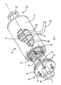
- a module in perspective view, with portions broken away, indicated generally by reference numeral 10, received within a relatively close-fitting cylindrical shell 11 to show a stack of cylindrical cartridges 20 coaxially held therewithin by tie-rods 13 having threaded ends.
- the tie-rods which are equidistantly spaced along the circumference of the stack, traverse the length of the shell and the cartridges are slidably fitted therein with gaskets 15 between successive cartridges.
- Each cartridge is made with from 10 to 50 arrays, each array having at least 2, preferably from 15 to 500, fibers 16, the bores 17 of which discharge permeate in a plane orthogonal to the longitudinal axis of the module.
- the shell 11 may be formed from a synthetic resinous material adapted to withstand the pressure at which feed is to be treated.
- the shell has an inner end surface 12, only one end of which is visible, which is preferably smooth.
- the tie-rods 13 extend from the end of the shell and protrude through a stepped flange 19 of coupling 22 with O-rings (not shown) to seal between the tie-rods and the stepped flanges.
- the ends of the tie-rods are threaded so as to allow the stepped flange 19 to be through-bolted with nuts 24, tightly compressing the upper and lower faces of every cartridge in the assembly, one against the other, or against a gasket, in fluid-tight relation.
- Essentially identical fluid couplings 22 and 23 at the ends of the shell serve to direct the flow of a feedstream over the fibers within the stack.
- the tie-rods 13 and nuts 24 serve to provide enough pressure on the assembly comprising the shell 11, fluid couplings 22 and 23, and the stack of cartridges 20, to confine the feedstream within the stack.
- Through-passages 14 are provided in coupling 22 to receive the tie-rods 13.
- An O-ring (not shown) provides a fluid-tight seal between the coupling 22, especially the stepped flange 19, and the surface 12 inside the shell 11, to ensure that no portion of the permeate leaks over the exterior of the shell.
- Another gasket (not shown) provides a seal between the inner face of the coupling and the cartridge at each end of the stack, preventing the feedstream from leaking into the permeate side.
- the two fluid couplings 22 and 23 are provided with flanges 26 and 27, respectively, for attachment to appropriate fluid conduits which deliverthe untreated feedstream, and lead away the treated feedstream or concentrate.
- a permeate outlet from the shell is indicated at 28.
- the module in the form shown in Fig. 1 is particularly well-adapted for use in a filtration operation.
- Fluid feed under elevated pressure in the range from about 120 kPa (3 psig) to about 5000 kPa (725 psig) is introduced through coupling 22 to flow transversely over the fibers in the stack. Feed may enter at subatmospheric pressure if the permeate is removed under vacuum. Components of the feed capable of passing through the membranes under the transmembrane pressure differential generated, permeates through the walls of the fibers and into the permeate side of the shell, and leaves through permeate outlet 28, while the remaining components of the feedstream (the concentrate) leave through the coupling 23.
- the width of the border of a frame is sufficient to provide adequate support for, and negate damage to, the terminal portions of the fibers when subjected to the force of the incoming feedstream and to meet the structural requirements of the module.
- Each section may be from about 10 mm to about 50 mm wide; its thickness depends upon the outside diameter of the fibers, and if the frame is to be grooved. Preferably, if ungrooved, from 0.5 to 3 times fiber o.d.; if grooved, from 1.5 to 5 times fiber o.d.
- Organic fibers are typically made with an outside diameter in the range from about400 ⁇ m to about 2 mm, and wall thickness ranging from about 5 microns to about 2 mm; these dimensions are larger for ceramic fibers.
- the void space within a stack may range from about 20% to about 95% of the internal volume of the central conduit through the stack, the void space depending upon the particular end use of the stack in a module.
- the packing density in a module is defined by membrane area per unit internal volume of module and has dimensions of inverse meter (m- 1 ).
- each wafer has an array of 72 fibers, has an o.d. of 188 mm, an inside diameter (i.d.) of 155 mm, and a center-to-center transverse spacing of fibers of 2 mm.
- the center-to-center spacing of fibers in the horizontal plane ranges from about 1.2 to about 5 times the outside diameter of a fiber.
- the void fraction in the central conduit of the cartridge will vary in the range from about 0.3 to about 0.9, typically in the range from 0.4 to 0.8.
- the choice of fiber spacing and thickness of frame will determine packing density of the fibers. Such density is chosen to provide the maximum membrane area per unit volume of module without adversely affecting the flow of the feedstream through the stack.
- the result of forming a stack of cartridges and feeding the feed across the fibers is that permeate is discharged in opposite directions from the bores of fibers while the concentrate is discharged longitudinally through the module.
- the length of the terminal portion of a fiber held in the frame's border will typically range from about 0.5 cm to about 5 cm, preferably from about 1 cm to about 2.5 cm, depending upon the diameter and length of the fiber between opposed portions of the border, inter alia.
- a fiber 0.7 mm in diam. and 10 cm long may be held by terminal portions 1 cm long near each end.
- a fiber of the same diameter and 50 cm long may be held by terminal portions 2.5 cm long near each end, or by only 1 cm. From about 5% to about 50% of the overall length of a fiber may be used to secure the fiber, chord-wise, in each opposed portion of a border of a frame.
- a stack of cartridges, bonded or gasketed one to another, seriatim form an elongated conduit having a wall thickness which is determined by the width of the border of the frames and not the thickness of a frame.
- a frame though relatively thin, is rigid in that, when on edge, it can only be bent around an axis which lies in the plane of the frame. The conduit is therefore able to withstand high hydraulic pressure exerted by the feed.
- fibers in successive arrays are preferably essentially free from contact, not only with one another in the same array, but with fibers in an adjacent array. In a preferred embodiment, it is only during a module's operation, under flow conditions which cause the fibers to sag, that there may be contact between fibers in adjacent arrays, which thus support each other.
- the particular method of bonding the fibers to the frame is not narrowly critical, the choice being dependent upon the materials of the frame and the fiber, and the cost of bonding.
- Use of a compatible adhesive mainly ensures that the mechanical grip exerted by opposed grooves around a fiber, is fluid-tight.
- the rings are provided with directly aligned opposed sets of half-pipe grooves 33 and 33' in the rings' upper surfaces 31 u (see Fig S-3) the grooves being chord segments adapted (see Figs 2 and S-2) to snugly accommodate an array 34 of a multiplicity of fibers 16 which are coplanarly disposed in laterally spaced apart relationship in the sets of grooves 33 and 33' in the upper surface 31 u.
- the ends of the fibers protrude through opposed points in the periphery of the opposed portions of the border, to allow the bores 17 (Fig S2-A) to discharge permeate.
- each ring is ungrooved.
- the depth of each groove is preferably about the outside diameter of a fiber so that the upper surface of the fiber is substantially coplanar with the upper surface 31 u.
- the depth is not narrowly critical; it can be less than the diameter of the fibers since the fibers are compressible; or it can be more than the diameter of the fibers since a thin layer ( ⁇ 1 mm) of adhesive will fill the space above the fibers.
- the fibers 16 are held by their ends in a clamping means which is preferably grooved with corresponding grooves to facilitate positioning the fibers in the upper surface 31 u.
- the upper surface 31 u is pre-coated with a quick-curing adhesive (not shown) before the fibers are placed in the chord-wise grooves, and when the fibers are placed in the grooves, they are coated with more adhesive.
- the adhesive is chosen to cure initially to a semi-rigid, compressible mass sufficiently rigid to hold the fibers in their grooves until the next ring is positioned.
- Such initial cure is preferably effected within less than 1 min, preferably ⁇ 10 secs, and typically essentially instantaneously in ⁇ 1 sec, by a fast-acting initiator which generates free radicals, such as exposure to a source of ultraviolet (UV) tight of sufficient intensity to cure the adhesive and secure the fibers in their respective chordwise grooves.
- a fast-acting initiator which generates free radicals, such as exposure to a source of ultraviolet (UV) tight of sufficient intensity to cure the adhesive and secure the fibers in their respective chordwise grooves.
- UV ultraviolet
- the clamping means are then released, and another ring 31 (or 31 S to make a slotted cartridge) is placed over the just-adhesively secured fibers, and the step of positioning another array of fibers is repeated.
- the ring 31 S is pre-formed, preferably by injection molding, with the slots 36 and 36' and the grooves 33 and 33' precisely positioned in the ring 31S, so that, when vertically assembled, one directly upon the other, though radially displaced, a portion of every slot in each half-section of ring is in open communication with a portion of a slot directly above it, and also with a portion of a slot directly beneath it, except of course, the bottommost and uppermost rings (end frames).
- the purpose of such communication is to permit resin injected into either the first or the last slot, to fill every slot in the cartridge, as will be explained in greater detail herebelow.
- a wafer indicated generally by reference numeral 40 having an annular laminar frame in the form of a square ring frame 41 which borders (frames) a through-passage 42.
- the ring is provided grooves 43 and 43' in the ring's upper surface 41 u (see Fig 4A) snugly to accommodate individual fibers 16 of an array 44 in the upper surface 41 u so that permeate is discharged in opposed directions through the bores 17 of the fibers.
- the lower surface 41 b of the square ring 41 is ungrooved and the upper surfaces of the fibers 16 are substantially coplanar with the upper surface 41u.
- Slots 46 and 46' are cut in opposite portions of the ring frame 41.
- the length of each slot is slightly greater than one-fourth the length of a side of a rectangle drawn with the longitudinal centerlines of the slots.
- Figs 5 and S-5 there is shown a single cartridge 20 (without end-frame) during construction, specifically to illustrate how the arrays of successive wafers are staggered relative to one another so as to contact fluid flowing through the through-passage more efficiently.
- the fibers are radially displaced relative to one another, but they could be laterally displaced in vertically spaced apart relationship, as shown in Fig 7.
- the grooves 33 have fibers 16 placed and held therein by adhesive 35, and the walls 18 of fibers are slightly compressed by the next succeeding ring without significantly restricting the inside diameter.
- a cartridge 150 is assembled by placing individual wafers 50, as illustrated in Fig S-4, one upon another, starting with the first wafer 50F and finishing with the last wafer 50L. Before post-potting the cartridge, it is clamped between a bottom end frame 57 and an uppermost end frame 53, both ungrooved (neither shown here, see Fig S-9).
- Fig S-9 after the last wafer 50L is placed on the assembly of wafers 50, it is sandwiched between uppermost and bottom end frames 53 and 57, (Fig 9) respectively, before inserting locating rods (not shown) through the tie-rod holes 52.
- the uppermost end frame 53 has a potting hole 55 in it, as does the bottom end frame 57 so that liquid resin can be flowed across all slots in the cartridge when its wafers are later post-potted.
- the cartridge 150 is then clamped with clamps (not shown) to provide a near-fluid-tight zone around the exposed fibers.
- the cartridge is then post-potted with a conventional potting resin (not shown) injected into potting hole 55 under low pressure sufficient to fill potting channels formed by successive slots in each wafer, using the upper and lower potting plates, respectively.
- the materials for the frames of a wafer may be inorganic but are preferably either thermoplastic or thermosetting synthetic resinous materials, optionally reinforced with glass fibers, boron or graphite fibers and the like, if great strength is desired.
- thermoplastic materials derived from a monoolefinically unsaturated monomer, are preferred for relatively low temperature service below 100°C, these being chosen so as to be sufficiently compatible with the material of the fibers to produce a lasting, fluid-tight bond.
- Such thermoplastic materials may be crystalline, such as polyolefins, particularly high density polyethylene, polyamides (nylon), polycarbonates and the like, semi-crystalline such as polyetherether ketone (PEEK), or substantially amorphous, such as poly(vinyl chloride) (PVC) and the like.
- PVC poly(vinyl chloride)
- Other useful commercially available materials are polypropylene, acrylonitrile-butadiene-styrene (“ABS”), polyacetal, polyesters and modified or blended polyphenylene oxide (PPO).
- an elliptical, rectangular or other polygonal frame may be constructed and provided with an array.
- Ungrooved rings having a thickness from about one-half (0.5) to about one and one-half (1.5) times the outside diameter of a fiber may be used with relatively little concern for their strength.
- a portion of the front surface of which is illustrated in Fig 7 in greatly enlarged detail the smoothly planar face of lowermost ring 41 is coated with a thick layer (about 1 mm - 3 mm) of adhesive 45 thicker than a fiber 16, and fibers are spaced apart and held until a successive (next lowermost) ring 41 is placed and pressed onto the adhesive which is then cured.
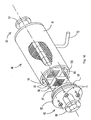
- FIG 10 there is shown a module 60 in which is mounted a stack of rectangular cartridges 150.
- the module is provided with a cylindrical shell 61, and flanges 66 and 67 on couplings 62 and 63, respectively, between which the stack is held.
- the inner diameter of the shell is preferably just larger than the diagonal of a cartridge but the inner surface 64 of the shell does not need to guide the cartridges into position.
- a gasket 68 provides a seal between the coupling 62 and the end of shell 61.
- the cartridges are mounted by passing tie-rods 69 through passages in the corners of the cartridges. Threaded ends of the tie-rods project through stepped flange 65 which is secured in position with nuts 71.
- a screen 76 with a mesh interior 77 is provided at the feed end of the module to filter out large particles. Feed is introduced through coupling 62, concentrate leaves through coupling 63, and permeate leaves through outlet 72.
- another module may be used as a mass transfer device to perform fluid-to-fluid transfer operations between any appropriately chosen first fluid flowing through the lumen of the fibers 16, and another appropriately chosen second fluid flowing through the stack externally to the fibers, provided the module is also fitted with an inlet (not shown) for the first fluid.
- the outlet for the first fluid is furnished by the permeate outlet 28 of the module.
- appropriate fluid-tight seals are provided between the inside surface of the shell and the periphery of the stack of cartridges.
- Preferred adhesives are U-V (ultraviolet) light curable resins such as Dymax 186m polyvinyl ethyl ethers, copolymers of acrylate ester with acrylic acid, epoxy resins and the like which form a fluid-tight bond between the fibers and the borders of the frames.
- Dymax 186m polyvinyl ethyl ethers copolymers of acrylate ester with acrylic acid, epoxy resins and the like which form a fluid-tight bond between the fibers and the borders of the frames.
- the adhesive sets (or cures) in two stages. In the first stage the adhesive sets sufficiently to hold the array in place, but is not fully set (or fully cured). The adhesive bonds the succeeding frame to the array when the adhesive is fully set in the second stage.
- the adhesive may be fully cured in a single step.
- the number of fibers in an array is arbitrary, typically being in the range from about 10 to about 1000. By way of illustration, if each wafer is 30 cm in diameter, 150 fibers each having an o.d. of 1.0 mm may be used in an array.
- the apparatus and basic separation process of this invention may be used in the recovery and separation of a wide variety of commercially significant materials some of which, illustratively referred to, include (a) the recovery of water from brackish or sea water; (b) the recovery and concentration of salts, particularly those of ammonium, the alkali metal and alkaline earth metals such as the halides, sulfates, sulfites nitrates and hydroxides; and organic fluids including glycerine, lactic acid, alcohol, glycols and tanning extracts; (c) ion exchange processes; and, (d) separation of components which normally form azeotropes or have substantially the same boiling points, or ammonia from fluid organic amines; treatment of industrial waste streams such as radioactive waste, sulfite pulps, cannery waste, and the like.
- salts particularly those of ammonium, the alkali metal and alkaline earth metals
- organic fluids including glycerine, lactic acid, alcohol,
- any of the foregoing processes will benefit from method of using the module having the structural features described hereinabove.
- the feedstream is flowed over the hollow fibers in a direction essentially orthogonal to the plane in which the fibers lie; that portion of the feedstream which permeates the walls of the fibers into the permeate zone is collected and conducted away from the permeate zone; and, concentrate which does not permeate the walls and remains in the feed zone is flowed away from the feed zone and out of the module.
- the grooves are not dimensioned to provide a high degree of mechanical grip to avoid damaging polymeric membranes.
- a typical preferred method for constructing a cartridge of wafers from such frames comprises, (i) positioning a first frame to receive an array, (ii) applying enough of a viscous but fluid adhesive to coatthe grooves, (iii) placing an array of fibers in the grooves, one fiber to a groove while the fibers are held in spaced-apart relationship, (iv) applying additional adhesive to ensure that it fills the spaces between fibers and cover them, (v) positioning a second frame on the adhesive-coated fibers, and, (vi) waiting until the adhesive is cured sufficiently to secure the fibers in position before releasing their ends. After the last wafer is assembled to form a cartridge, they are held between top and bottom end frames and the cartridge is post-potted.
- the grooves are dimensioned to provide a high degree of mechanical grip without damaging the fibers.
- Atypical preferred method for constructing a cartridge of wafers from such frames comprises, (i) positioning a first frame to receive an array, (ii) placing an array of fibers in the grooves, one fiber to a groove while the fibers are held in spaced-apart relationship, (iii) applying enough of a viscous but fluid adhesive to ensure that it fills the spaces between fibers and cover them, and, (iv) positioning a second frame on the adhesive-coated fibers before releasing the ends of the fibers. Though each fiber is gripped in a groove, enough adhesive is drawn around the fiber and into the groove to provide a fluid-tight seal between the fiber and the groove. The ends of the fibers can be released because they are held sufficiently well until the adhesive is essentially completely cured.
- the viscosity of the adhesive is preferably in the range from about 10 cps to 1000 cps at room temperature.
- an ultraviolet (UV) light-curable resin is used as the adhesive, and the adhesive distributed over the fibers and first frame after the fibers are positioned over the frame. While still being held in the fiber-positioning clamps, a second frame is positioned over the adhesive-embedded fibers, and the resin then exposed to UV light to cure it. The fibers are then released from the clamps.
- UV ultraviolet
- the end closures 22 and 23 are removably affixed to each end of the shell because the shell is meant to be reused when the cartridges are replaced.
- a disposable module may be constructed in which there is no intention to replace the cartridge(s) or save and reuse the shell.
- the end closure 22 and 23 are fixedly, that is, non-removably secured to the ends of the shell.
- each of the following examples a single cylindrical cartridge is used in a cylindrical module.
- Each example is run with a cartridge in a module which are each essentially identical to those used in the other.
- a permanent module was not available; the cartridge was mounted with temporary means; therefore dimensions of the module are not provided.
- Each cartridge is constructed with 48 arrays.
- the angular displacement between successive wafers is 60°.
- the height of the cartridge is 108 mm and the membrane area 1.426 m 2 .
- Each circular wafer has the following specifications:
- a nanofiltration membrane is typically used to filter surface water containing high concentrations of soluble naturally occurring organic matter such as humic and fulvic acids. These substances cause the water to appear brownish in color and upon chlorination in water treatment facilities, they react to form toxic trihalomethane compounds. These substances are reported to have a molecular weight in the range from 700 to 80,000 (see “Removal of Humic Substances From Natural Water by Reverse Osmosis” by Hallvard Odegaard and Suporn Kootetep, Water Research, vol 16, pp 613-620). To simulate such an application, the following test is conducted:
- the above-specified cartridge is equipped with a "loose" nanofiltration membrane characterized by 25% NaCi rejection of a 1000 ppm feed solution at 75 psig.
- the feedwater is made up with reverse-osmosis water and synthetic humic acid such that the observed color level is 200 Pt-Co color units.
- a color unit is equivalent to 1 mg/L of Pt as chloroplatinate ion. This measurement technique is described in Standard Method for the Examination of Water and Waste-water (American Public Health Association, Washington, D.C., publisher).
- the operating pressure is 75 psig and the feed flow rate is 30 gpm. Based on this flow rate the feedstream Reynolds number is 200 (based on the o.d. of the fiber).
- the rejection values are of color units and the flux is reported in US gal/ft 2 /24 hr (gfd). To convert to liters/m 2 /hr, multiply by 1.706.
- the cartridge with the above specifications is constructed with a polymeric membrane having pore sizes in the range from 0.1 to 0.25 mf..l.
- the feedstream is an activated sludge with 15 g/L of suspended biological waste solids.
- the module is operated at a flow rate of 60 gpm and a pressure of 10 psi.
- the long term steady state flux is observed to be 50 gfd.
- the permeate is of consistently high quality with turbidity counts of less than 0.1 NTU (Nephelometric Turbidity Unit) indicating nearly 100% rejection of the suspended solids.
- NTU is a measure of the light scattered at an angle of 90° by particles in the water. It is an EPA-recognized measurement of water clarity.
- the module in transverse flow has the ability to operate on feeds containing high suspended solids concentrations without significant fouling and no clogging of the flow passages over an extended period of time.
- the essential requirements are that the feedstream be flowed through at least one cartridge in which the fibers are disposed transverse to the direction of flow of the feedstream.
- the manner in which the successive wafers are made into a cartridge will depend in part upon the pressure at which the cartridge is to operate, the higher the pressure, the more pains taken to ensure a fluid-tight seal between fibers and frames in each successive array.
- Most preferred for relatively high pressure operation are grooved frames, and enough time is allowed between successive wafers to be sure that the bonding agent secures the fibers and frames on either side thereof, before releasing the fibers.
- ungrooved frames may be used and a viscous resin used to seal the fibers between adjacent frames.
- the fibers may be released prior to the resin having cured, and a successive frame placed on the still-curing resin provided it is sufficiently compressible to result in a fluid-tight seal without damaging the fibers.
- sufficiently compressible we mean that the successive frame may be pressed onto the still-curing resin with a pressure in the range from 1 psig to 50 psig depending upon the fragility or compressibility of the fibers.
Landscapes
- Chemical & Material Sciences (AREA)
- Chemical Kinetics & Catalysis (AREA)
- Separation Using Semi-Permeable Membranes (AREA)
Applications Claiming Priority (4)
| Application Number | Priority Date | Filing Date | Title |
|---|---|---|---|
| US845641 | 1992-03-04 | ||
| US07/845,641 US5232593A (en) | 1992-03-04 | 1992-03-04 | Cartridge of hollow fiber membrane wafers and module containing stacked cartridges |
| US992560 | 1992-12-18 | ||
| US07/992,560 US5366625A (en) | 1992-03-04 | 1992-12-18 | Cartridge of hybrid unitary wafers of hollow fiber membranes and module containing a stack of post-potted cartridges |
Publications (2)
| Publication Number | Publication Date |
|---|---|
| EP0560720A2 true EP0560720A2 (fr) | 1993-09-15 |
| EP0560720A3 EP0560720A3 (en) | 1993-12-15 |
Family
ID=27126591
Family Applications (1)
| Application Number | Title | Priority Date | Filing Date |
|---|---|---|---|
| EP19930810156 Withdrawn EP0560720A3 (en) | 1992-03-04 | 1993-03-03 | Cartridge of hollow fiber membrane wafers and module containing stacked cartridges |
Country Status (5)
| Country | Link |
|---|---|
| US (1) | US5366625A (fr) |
| EP (1) | EP0560720A3 (fr) |
| JP (1) | JPH06165923A (fr) |
| AU (1) | AU3388993A (fr) |
| CA (1) | CA2090847A1 (fr) |
Cited By (4)
| Publication number | Priority date | Publication date | Assignee | Title |
|---|---|---|---|---|
| EP1005896A4 (fr) * | 1998-05-14 | 2002-02-13 | Daicen Menbrane Systems Ltd | Module de type a fibres creuses |
| DE10242078A1 (de) * | 2002-09-09 | 2004-03-18 | Saxonia Bio Tec Gmbh | Faserkassette und modular aufgebautes Kassettensystem |
| DE10332116B3 (de) * | 2003-07-09 | 2005-02-03 | Klaus Dr. Rennebeck | Hohlfaseranordnung |
| KR101942817B1 (ko) * | 2018-04-13 | 2019-01-29 | (주)신우엔지니어링 | 중공사막 필터부 교체형 가압식 중공사막 모듈 |
Families Citing this family (38)
| Publication number | Priority date | Publication date | Assignee | Title |
|---|---|---|---|---|
| US5639373A (en) | 1995-08-11 | 1997-06-17 | Zenon Environmental Inc. | Vertical skein of hollow fiber membranes and method of maintaining clean fiber surfaces while filtering a substrate to withdraw a permeate |
| NL9402090A (nl) * | 1994-12-09 | 1996-07-01 | Tno | Modulair opgebouwde overdraaginrichting voor de overdracht van stof en/of warmte vanuit de ene mediumstroom naar een andere mediumstroom, alsmede module daarvoor. |
| US5586773A (en) * | 1995-06-19 | 1996-12-24 | General Electric Company | Gas-path leakage seal for a gas turbine made from metallic mesh |
| US7087173B2 (en) * | 1995-08-11 | 2006-08-08 | Zenon Environmental Inc. | Inverted cavity aerator for membrane module |
| US8852438B2 (en) * | 1995-08-11 | 2014-10-07 | Zenon Technology Partnership | Membrane filtration module with adjustable header spacing |
| KR20050046718A (ko) * | 1995-08-11 | 2005-05-18 | 제논 인바이런멘탈 인코포레이티드 | 수직한 중공사 멤브레인 다발 및 섬유 표면을 깨끗하게유지시키는 방법 |
| US20040238432A1 (en) * | 1995-08-11 | 2004-12-02 | Mailvaganam Mahendran | Membrane filtration module with adjustable header spacing |
| US5785723A (en) * | 1995-10-23 | 1998-07-28 | Respiratory Support Products | Positive pressure filter system for inflatable blanket heaters |
| JP3686918B2 (ja) * | 1996-10-16 | 2005-08-24 | 森村興産株式会社 | 汚水、廃水等の固液分離用濾過装置 |
| RU2148649C1 (ru) * | 1998-03-31 | 2000-05-10 | Институт белка РАН | Способ получения полипептидов в бесклеточной системе (варианты) и устройство для его осуществления |
| DE10045227C1 (de) * | 2000-09-13 | 2002-02-07 | Vosenkaul Klaus | Membranfilter für die Wasseraufbereitung |
| US6706180B2 (en) * | 2001-08-13 | 2004-03-16 | Phase Inc. | System for vibration in a centrifuge |
| JP2003093828A (ja) * | 2001-09-27 | 2003-04-02 | Mitsui Eng & Shipbuild Co Ltd | 分離膜モジュールを備えた蒸留装置、および蒸留塔 |
| DE10220452B4 (de) * | 2002-05-07 | 2006-10-19 | Gkss-Forschungszentrum Geesthacht Gmbh | Vorrichtung zur Abtrennung einer Komponente aus einem Gasgemisch |
| DE10227721B4 (de) * | 2002-06-21 | 2008-03-13 | Hermsdorfer Institut Für Technische Keramik E.V. | Verfahren zur Herstellung eines Bündels keramischer Kapillaren für ein Separationsmodul |
| US7335301B2 (en) * | 2002-11-22 | 2008-02-26 | Koch Membrane Systems, Inc. | Fold protection for spiral filtration modules utilizing UV cured adhesive and method of providing same |
| WO2004080601A2 (fr) | 2003-03-11 | 2004-09-23 | Phase Inc. | Centrifugeuse a decharge modulable des materiaux denses |
| US6971525B2 (en) | 2003-06-25 | 2005-12-06 | Phase Inc. | Centrifuge with combinations of multiple features |
| US7371322B2 (en) | 2003-07-30 | 2008-05-13 | Phase Inc. | Filtration system and dynamic fluid separation method |
| WO2005011833A2 (fr) | 2003-07-30 | 2005-02-10 | Phase Inc. | Systeme de filtration a nettoyage ameliore et separation de fluide dynamique |
| US7282147B2 (en) | 2003-10-07 | 2007-10-16 | Phase Inc. | Cleaning hollow core membrane fibers using vibration |
| US7628916B2 (en) * | 2005-01-26 | 2009-12-08 | Celgard Llc | Hollow fiber module |
| CN101321577B (zh) * | 2005-12-07 | 2012-10-17 | 陶氏环球技术有限责任公司 | 螺旋卷组件的插入点密封 |
| US8114276B2 (en) | 2007-10-24 | 2012-02-14 | Baxter International Inc. | Personal hemodialysis system |
| US8158001B2 (en) | 2008-06-05 | 2012-04-17 | Celgard Llc | Wafer-shaped hollow fiber module for in-line use in a piping system |
| JP5416432B2 (ja) * | 2009-02-24 | 2014-02-12 | 株式会社潤工社 | 脱気装置 |
| PL2756875T3 (pl) | 2009-11-12 | 2016-10-31 | Urządzenie oczyszczające powietrze do usuwania zanieczyszczeń powietrza ze strumienia powietrza | |
| US8449659B2 (en) | 2010-09-28 | 2013-05-28 | Celgard Llc | Liquid degassing membrane contactors, components, systems and related methods |
| JP6277560B2 (ja) * | 2013-02-15 | 2018-02-14 | ケラダ,マー | 浸透ポテンシャルを利用する装置、装置の作製方法、及び使用方法 |
| RU2708861C2 (ru) | 2015-03-24 | 2019-12-11 | Арстрома Ко., Лтд. | Устройство разделения текучих сред, включающее мембрану для разделения текучих сред, и мембранный модуль для разделения текучих сред |
| US10477883B2 (en) | 2015-08-25 | 2019-11-19 | Cornelius, Inc. | Gas injection assemblies for batch beverages having spargers |
| US10785996B2 (en) | 2015-08-25 | 2020-09-29 | Cornelius, Inc. | Apparatuses, systems, and methods for inline injection of gases into liquids |
| KR20190020060A (ko) | 2016-08-29 | 2019-02-27 | 이엠디 밀리포어 코포레이션 | 압축된 주름 구성 필터에 대한 고정된 강성 벽 장치 |
| WO2020069607A1 (fr) | 2018-10-01 | 2020-04-09 | Membio Inc. | Bioréacteur de culture cellulaire |
| US11040314B2 (en) | 2019-01-08 | 2021-06-22 | Marmon Foodservice Technologies, Inc. | Apparatuses, systems, and methods for injecting gasses into beverages |
| WO2021155469A1 (fr) | 2020-02-05 | 2021-08-12 | Membio Inc. | Bioréacteur de culture cellulaire avec contrôle de zone |
| JP7444658B2 (ja) * | 2020-03-18 | 2024-03-06 | メタウォーター株式会社 | ろ過装置 |
| DE102022208114A1 (de) * | 2022-08-04 | 2024-02-15 | Robert Bosch Gesellschaft mit beschränkter Haftung | Befeuchtungsvorrichtung für eine Brennstoffzelleneinheit |
Family Cites Families (8)
| Publication number | Priority date | Publication date | Assignee | Title |
|---|---|---|---|---|
| US3342729A (en) * | 1964-12-09 | 1967-09-19 | Dow Chemical Co | Permeability separatory cell and apparatus and method of using the same |
| FR2236537B1 (fr) * | 1973-07-11 | 1977-12-23 | Rhone Poulenc Ind | |
| US5164081A (en) * | 1989-03-24 | 1992-11-17 | The Standard Oil Company | Apparatus for separation and for treatment of fluid feedstreams, wafers for use therein and related methods |
| US5174900A (en) * | 1989-03-24 | 1992-12-29 | The Standard Oil Company | Apparatus for separation and for treatment of fluid feedstreams, wafers for use therein and related methods |
| US4959152A (en) * | 1989-03-24 | 1990-09-25 | The Standard Oil Company | Hollow fiber separation module and method for the use thereof |
| GB8921458D0 (en) * | 1989-09-22 | 1989-11-08 | Univ Strathclyde | Cell culture apparatus |
| US5182019A (en) * | 1990-08-17 | 1993-01-26 | Zenon Environmental Inc. | Cartridge of hybrid frameless arrays of hollow fiber membranes and module containing an assembly of cartridges |
| US5104535A (en) * | 1990-08-17 | 1992-04-14 | Zenon Environmental, Inc. | Frameless array of hollow fiber membranes and module containing a stack of arrays |
-
1992
- 1992-12-18 US US07/992,560 patent/US5366625A/en not_active Expired - Fee Related
-
1993
- 1993-03-01 AU AU33889/93A patent/AU3388993A/en not_active Abandoned
- 1993-03-02 CA CA002090847A patent/CA2090847A1/fr not_active Abandoned
- 1993-03-03 EP EP19930810156 patent/EP0560720A3/en not_active Withdrawn
- 1993-03-04 JP JP5044144A patent/JPH06165923A/ja active Pending
Cited By (5)
| Publication number | Priority date | Publication date | Assignee | Title |
|---|---|---|---|---|
| EP1005896A4 (fr) * | 1998-05-14 | 2002-02-13 | Daicen Menbrane Systems Ltd | Module de type a fibres creuses |
| DE10242078A1 (de) * | 2002-09-09 | 2004-03-18 | Saxonia Bio Tec Gmbh | Faserkassette und modular aufgebautes Kassettensystem |
| DE10393754B4 (de) * | 2002-09-09 | 2006-04-27 | Saxonia Bio Tec Gmbh | Hohlfaserkassette und modular aufgebautes Kassettensystem |
| DE10332116B3 (de) * | 2003-07-09 | 2005-02-03 | Klaus Dr. Rennebeck | Hohlfaseranordnung |
| KR101942817B1 (ko) * | 2018-04-13 | 2019-01-29 | (주)신우엔지니어링 | 중공사막 필터부 교체형 가압식 중공사막 모듈 |
Also Published As
| Publication number | Publication date |
|---|---|
| JPH06165923A (ja) | 1994-06-14 |
| AU3388993A (en) | 1993-09-09 |
| US5366625A (en) | 1994-11-22 |
| EP0560720A3 (en) | 1993-12-15 |
| CA2090847A1 (fr) | 1993-09-05 |
Similar Documents
| Publication | Publication Date | Title |
|---|---|---|
| EP0560720A2 (fr) | Cartouche à disques de membranes sous forme de fibres creuses et module comprenant des cartouches empilées | |
| US5182019A (en) | Cartridge of hybrid frameless arrays of hollow fiber membranes and module containing an assembly of cartridges | |
| US5104535A (en) | Frameless array of hollow fiber membranes and module containing a stack of arrays | |
| US5232593A (en) | Cartridge of hollow fiber membrane wafers and module containing stacked cartridges | |
| US4855058A (en) | High recovery spiral wound membrane element | |
| JP5351197B2 (ja) | 中空糸膜モジュールとその製造方法および中空糸膜モジュール組立体とそれらを使用した懸濁水の浄化方法 | |
| KR950007919B1 (ko) | 고회수 나선 권선형 막 여과장치 | |
| EP0238737B1 (fr) | Assemblage de membranes pour disque de séparation de fluides | |
| US4451369A (en) | Fluid separation apparatus | |
| US5137631A (en) | Multiple bundle permeator | |
| CN1078092C (zh) | 中空纤维过滤器芯 | |
| US20020108906A1 (en) | Multi-stage filtration and softening module and reduced scaling operation | |
| EP1666128B1 (fr) | Sous-module membrane en fibres creuses et module comprenant un tel sous-module | |
| EP3283197B1 (fr) | Ensemble filtration comprenant des bioréacteurs et modules à membranes, enroulés en spirale, placés dans des cuves sous pression séparées | |
| US10286361B2 (en) | Filtration assembly including spiral wound bioreactors and hyperfiltration membrane modules | |
| US4761229A (en) | Multi-leaf membrane module | |
| JPH11300173A (ja) | 中空糸膜モジュール | |
| US12337282B2 (en) | Potted flat sheet membrane filtration module | |
| JP2004524140A5 (fr) | ||
| US12616937B2 (en) | Filtration units and assembly, and methods of making and using same | |
| WO2023158956A1 (fr) | Unités et ensemble de filtration, et leurs procédés de fabrication et d'utilisation | |
| JPS6233503A (ja) | 流体分離装置用膜セツト | |
| CA2383962A1 (fr) | Module de filtration et d'adoucissement multi-etages et operation a echelle reduite | |
| JPH06277459A (ja) | 膜分離装置 |
Legal Events
| Date | Code | Title | Description |
|---|---|---|---|
| PUAI | Public reference made under article 153(3) epc to a published international application that has entered the european phase |
Free format text: ORIGINAL CODE: 0009012 |
|
| AK | Designated contracting states |
Kind code of ref document: A2 Designated state(s): AT BE CH DE DK ES FR GB GR IE IT LI LU MC NL PT SE |
|
| PUAL | Search report despatched |
Free format text: ORIGINAL CODE: 0009013 |
|
| AK | Designated contracting states |
Kind code of ref document: A3 Designated state(s): AT BE CH DE DK ES FR GB GR IE IT LI LU MC NL PT SE |
|
| RBV | Designated contracting states (corrected) |
Designated state(s): DE ES FR GB IT NL |
|
| 17P | Request for examination filed |
Effective date: 19940610 |
|
| 17Q | First examination report despatched |
Effective date: 19941213 |
|
| STAA | Information on the status of an ep patent application or granted ep patent |
Free format text: STATUS: THE APPLICATION IS DEEMED TO BE WITHDRAWN |
|
| 18D | Application deemed to be withdrawn |
Effective date: 19951003 |