EP0560729A2 - Cartouche d'encre pour tête d'impression d'une imprimante à jet d'encre - Google Patents
Cartouche d'encre pour tête d'impression d'une imprimante à jet d'encre Download PDFInfo
- Publication number
- EP0560729A2 EP0560729A2 EP93810169A EP93810169A EP0560729A2 EP 0560729 A2 EP0560729 A2 EP 0560729A2 EP 93810169 A EP93810169 A EP 93810169A EP 93810169 A EP93810169 A EP 93810169A EP 0560729 A2 EP0560729 A2 EP 0560729A2
- Authority
- EP
- European Patent Office
- Prior art keywords
- ink cartridge
- housing
- cartridge according
- ink
- end wall
- Prior art date
- Legal status (The legal status is an assumption and is not a legal conclusion. Google has not performed a legal analysis and makes no representation as to the accuracy of the status listed.)
- Granted
Links
- 239000006260 foam Substances 0.000 claims abstract description 18
- 238000005086 pumping Methods 0.000 claims abstract description 8
- 238000007789 sealing Methods 0.000 claims description 15
- 239000011324 bead Substances 0.000 claims description 5
- 241000272814 Anser sp. Species 0.000 claims description 3
- 239000000853 adhesive Substances 0.000 claims description 2
- 230000001070 adhesive effect Effects 0.000 claims description 2
- 238000000605 extraction Methods 0.000 claims 1
- 238000009423 ventilation Methods 0.000 description 6
- 229920001971 elastomer Polymers 0.000 description 3
- 239000012528 membrane Substances 0.000 description 3
- 229920002379 silicone rubber Polymers 0.000 description 3
- 239000004945 silicone rubber Substances 0.000 description 3
- 239000002390 adhesive tape Substances 0.000 description 2
- 229920000877 Melamine resin Polymers 0.000 description 1
- 229920005830 Polyurethane Foam Polymers 0.000 description 1
- 239000002313 adhesive film Substances 0.000 description 1
- 230000006835 compression Effects 0.000 description 1
- 238000007906 compression Methods 0.000 description 1
- 230000000994 depressogenic effect Effects 0.000 description 1
- 239000000806 elastomer Substances 0.000 description 1
- JDSHMPZPIAZGSV-UHFFFAOYSA-N melamine Chemical compound NC1=NC(N)=NC(N)=N1 JDSHMPZPIAZGSV-UHFFFAOYSA-N 0.000 description 1
- 238000000034 method Methods 0.000 description 1
- 239000004033 plastic Substances 0.000 description 1
- 229920003023 plastic Polymers 0.000 description 1
- 239000011496 polyurethane foam Substances 0.000 description 1
- 239000011148 porous material Substances 0.000 description 1
- 239000012815 thermoplastic material Substances 0.000 description 1
- 210000000115 thoracic cavity Anatomy 0.000 description 1
- 238000002604 ultrasonography Methods 0.000 description 1
Images


Classifications
-
- B—PERFORMING OPERATIONS; TRANSPORTING
- B41—PRINTING; LINING MACHINES; TYPEWRITERS; STAMPS
- B41J—TYPEWRITERS; SELECTIVE PRINTING MECHANISMS, i.e. MECHANISMS PRINTING OTHERWISE THAN FROM A FORME; CORRECTION OF TYPOGRAPHICAL ERRORS
- B41J2/00—Typewriters or selective printing mechanisms characterised by the printing or marking process for which they are designed
- B41J2/005—Typewriters or selective printing mechanisms characterised by the printing or marking process for which they are designed characterised by bringing liquid or particles selectively into contact with a printing material
- B41J2/01—Ink jet
- B41J2/17—Ink jet characterised by ink handling
- B41J2/175—Ink supply systems ; Circuit parts therefor
- B41J2/17503—Ink cartridges
- B41J2/17513—Inner structure
Definitions
- EP-A-408 241 describes a print head for an ink jet printer with an exchangeable ink cartridge: on a base plate of the print head, the nozzle plate is arranged on one side and a holder for the ink cartridge on the opposite side.
- the cartridge contains a foam body soaked in ink.
- the bottom of the cartridge housing On the side facing the base plate, the bottom of the cartridge housing has a cavity which is closed off from the outside by a rubber plug and is delimited from the foam body by a sieve.
- a needle protrudes from the base plate, the capillary of which communicates with the ink channels of the nozzle plate via cavities. The rubber plug is pierced with the needle when inserting the cartridge. Its tip then protrudes into the cavity.
- the cover on the opposite side of the housing has a ventilation opening that opens into another cavity.
- the present invention has for its object to design an ink cartridge of the type mentioned in such a way that the ink supply can be better used.
- the ink cartridge according to the invention for a print head of an ink jet printer comprises a housing which is closed on all sides and has an end wall which has an opening for receiving a tubular nozzle of the print head.
- the housing contains a foam body soaked in ink. It has snap-in elements for snapping into the snap-in means of the print head and a second, smaller opening for the air supply.
- the print head 1 is only indicated schematically. It consists of a rectangular base plate 2, from which a projection 3 protrudes along a narrow side. A nozzle plate 5 is installed in the end face 4 of this projection 3.
- the nozzle plate 5 contains a series of narrow ink channels. The pressure in these channels can be increased piezoelectrically or thermoelectrically, so that an ink droplet is ejected from the nozzle in question. The surface tension at the nozzle mouth then sucks the ejected ink volume out of an interior space 6 of a tubular nozzle 7 communicating with the nozzle channels.
- the flat end face 8 of the nozzle 7 is covered with a close-meshed sieve 9 and projects beyond the rear side 10 of the base plate 2.
- a prismatic tube with four side walls 11 protrudes from the base plate 2, into which an ink cartridge 20 is inserted.
- a sealing ring 12, shown in more detail in FIG. 5, is placed on the section of the connecting piece 7 projecting beyond the rear.
- the elastomeric sealing ring 12, for example made of silicone rubber, is tubular and has a flat front face 13 and a circumferential sealing bead 15 on the cylindrical outer circumference 14.
- the end face 13 supports the protruding edge of the screen 9 and protects it from tearing when the cartridge 20 is pulled out
- the sealing bead 15 seals the nozzle 7 against the cartridge housing. In operation, the end face 4 is directed downward and the interior 6 is full of ink.
- two opposite side walls 11 of the printhead 1 have coaxial bores 16.
- the ink cartridge 20 has a plastic housing 22 consisting of a hollow body 24 which is open at the bottom in the illustration according to FIG. 2 and is closed off by a cover 26 which is sealed or glued on.
- An end wall 28 of the housing 22 has an opening 30 with a cylindrical wall 32 for receiving the nozzle 7.
- the sealing bead 15 seals against the wall 32.
- the housing 22 is largely filled with an ink-soaked foam body 34.
- Two side walls 36 of the housing 22 have spherical cap-shaped projections 38 for snapping into the holes in the side walls 11 of the print head 1.
- a cavity 40 is formed between the foam body 34 and the housing 22, which can be filled with air or ink.
- a pumping element 42 projects into this cavity 40, in the embodiment according to FIG. 2 in the form of a piston pump.
- a cylindrical tube 44, in which a piston 46 is guided, is formed on the cover 26. The piston 46 is loaded by a spring 48 into the basic position shown in FIG. 2, in which a piston shaft 50 projects beyond the housing 22.
- the piston 46 is shown enlarged in FIG. 3. It consists of a piston crown 52 and the stem 50 snapped onto it. An O-ring 54 is inserted between two end faces of the stem 50 and the bottom 52 and seals against the cylindrical inner wall of the tube 44. The interior of the shaft 50 is connected to the atmosphere via openings 56.
- the piston crown 52 contains a check valve 58.
- a pin 64 molded onto a rotationally symmetrical membrane 62 is inserted into a central bore 60.
- the membrane 62 consists of an elastomer, for example of silicone rubber. On the periphery, it has a projecting, thin-walled, thoracic segment-shaped sealing bead 66 which seals against a flat end face 68 of the piston crown 52.
- the check valve 58 has a very low opening or closing pressure of a few m bar, for example at most 20 m bar.
- An opening 70 connects the outside of the membrane 62 to the interior of the shaft 50.
- the shaft 50 of the pumping goose 42 is pressed in until ink emerges from the nozzle plate 5.
- the print head 1 is expediently held with the nozzle plate 5 upward so that the air can escape from the space 6.
- the interior 6 is then filled with ink and the print head 1 is ready for operation.
- the shaft 50 is released, there is then a negative pressure of a few m bar inside the housing 22, so that no more ink can drip from the nozzle plate 5.
- the stroke volume of the piston 46 is preferably somewhat larger than the volume of the interior 6. This space 6 can be filled with a single push in of the piston 46. However, the check valve 58 also makes it possible to repeat the pumping process if a single push-in is not sufficient.
- FIGS. 6-8 differ from those according to FIGS. 2-4 only in the design of the pumping goose 42, so that the parts identical to the embodiment according to FIGS. 2-4 are partially omitted in the illustration according to FIGS. 6-8. Analog parts have the same reference numerals, so that a detailed description of these parts is unnecessary.
- the pump element 42 is designed as a bellows pump.
- the pumping element 42 according to FIG. 6 has a dome-shaped, elastomeric bellows 76 with a flange 78 which is clamped between a sleeve 80 pressed into the tube 44 and an end wall 82 of the tube 44.
- the wall 82 has an opening 84.
- the check valve 58 which can be designed, for example, in the same way as that according to FIGS. 3 and 4, is inserted here into the end wall 86 of the housing 22 opposite the end wall 28.
- the bellows 76 is a bellows which is pushed onto a tubular extension 88 of the wall 82.
- the check valve 58 is mounted here in the wall 82.
- FIG. 8 differs from that according to FIGS. 2-4 in that the spring 48 and the check valve 58 are missing.
- the piston 46 is pressed in two stages into the depressed position which is also shown. In a first stage, the piston is pushed in so that the O-ring 54 is still on the side of the radial opening 90 in the tube 44 facing the cover 26. This position can be determined by a locking stop (not shown) or by the outer end face 92 of the piston skirt 50 being flush with the outer face of the cover 26.
- the opening 90 can also be formed, for example, in the end wall 86 and can be closed in the delivery state, for example by an adhesive tape.
- the "two-phase movement" consists in pressing in the piston 46 and then detaching the adhesive tape.
- the opening 30 of the housing 22 is also sealed by an adhesive film which is removed before the ink cartridge 20 is inserted into the print head 1.
- the print head 1 has the same design as that according to FIG. 1, except that the sealing ring 12 is missing.
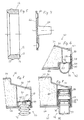
- the cartridge 120 of the embodiment according to FIG. 9 consists of a housing 121 with a prismatic hollow body 122 which is open on one side and has four side walls 123 and a rear wall 124 made of thermoplastic material and which is sealed on the free end edge of the hollow body 121, e.g. cover 125 welded on with ultrasound.
- Cover 125 engages with a circumferential rim 126 in a form-fitting manner in the inside of side walls 123.
- Adjacent to one narrow side, the cover 125 has a bore 127 in which the socket 7 fits.
- Adjacent to the opposite narrow side, the cover 125 has a small ventilation hole 128 which is aligned with a channel 130 formed by closely adjacent inner ribs 129 on the one side wall 123.
- the channel 130 opens out on the rear wall 124 into a ventilation cavity 132, likewise formed by ribs 131.
- An open-pore foam body 135 is inserted into the housing 121 with some compression.
- the foam is suitable e.g. "Melamine” foam (registered trademark) or polyurethane foam.
- Body 135 is soaked in ink.
- an elastomeric sealing film 136 e.g. made of silicone rubber, which has the size of the inner contour of the hollow body 122 at the free edge.
- the sealing film 136 has a circular hole 137 of smaller diameter coaxial to the bore 127. With the edge region adjacent to this hole 137, the film 136 seals the interior of the housing 121 against the end face 8 of the connector 7. In the area of the vent hole 128, the film 136 has a further recess.
- Two opposite side walls 123 of the hollow body 122 each have a spherical cap-shaped locking projection 139.
- the projections 139 snap into corresponding bores in the side walls 11 of the print head 1.
- two opposite side walls 123 of the housing 121 have molded-on grip cams 140, which make it easier for the cartridge 120 to be pulled out of the print head 1.
- the bore 127 and the ventilation hole 128 are closed with an adhesive strip or a sealing film 141 for transport and storage. This ensures clean handling of the cartridge 120.
- the film 141 closes both openings at the same time, it is avoided that the ventilation hole 128 could remain closed due to incorrect operation when inserting the cartridge 120, as a result of which a reliable operation of the print head 1 would not be possible. For this reason, the arrangement of the ventilation hole 128 in the cover 125 is advantageous.
- the channels 130, 132 formed by the ribs 129, 131 nevertheless ensure that the foam body 135 is exposed to atmospheric pressure, as desired from the opposite side of the bore 127.
- the nozzle 7 compresses the foam body 135 locally and therefore at the same time presses an ink supply into the interior 6 of the nozzle 7. This ensures reliable operation of the print head 1 immediately after the cartridge 20 is inserted. Because the relatively large-area sieve 9 of the nozzle 7 presses directly onto the foam body 135, the ink supply is guaranteed until the end of the ink supply. The contact pressure of the foam body 135 against the screen 9 of the nozzle 7 can be ensured by a positive engagement of the locking cams 139 in the locking holes of the print head 1.
Landscapes
- Ink Jet (AREA)
Applications Claiming Priority (4)
| Application Number | Priority Date | Filing Date | Title |
|---|---|---|---|
| DE9203206U DE9203206U1 (de) | 1992-03-10 | 1992-03-10 | Tintenpatrone für einen Druckkopf eines Ink Jet Printers |
| DE9203206U | 1992-03-10 | ||
| DE9300132U DE9300132U1 (de) | 1993-01-07 | 1993-01-07 | Tintenpatrone für einen Druckkopf eines Ink-Jet-Printers |
| DE9300132U | 1993-01-07 |
Publications (3)
| Publication Number | Publication Date |
|---|---|
| EP0560729A2 true EP0560729A2 (fr) | 1993-09-15 |
| EP0560729A3 EP0560729A3 (en) | 1994-06-22 |
| EP0560729B1 EP0560729B1 (fr) | 1996-05-15 |
Family
ID=25959256
Family Applications (1)
| Application Number | Title | Priority Date | Filing Date |
|---|---|---|---|
| EP93810169A Expired - Lifetime EP0560729B1 (fr) | 1992-03-10 | 1993-03-05 | Cartouche d'encre pour tête d'impression d'une imprimante à jet d'encre |
Country Status (4)
| Country | Link |
|---|---|
| EP (1) | EP0560729B1 (fr) |
| AT (1) | ATE138015T1 (fr) |
| DE (1) | DE59302549D1 (fr) |
| ES (1) | ES2087698T3 (fr) |
Cited By (25)
| Publication number | Priority date | Publication date | Assignee | Title |
|---|---|---|---|---|
| DE19512812A1 (de) * | 1994-11-29 | 1996-05-30 | Hewlett Packard Co | Nachfüllverfahren und Nachfüllvorrichtung für Tintenkassetteneinheiten |
| GB2298616A (en) * | 1992-07-31 | 1996-09-11 | Canon Kk | Liquid storing container for a recording apparatus |
| US5619239A (en) * | 1993-11-29 | 1997-04-08 | Canon Kabushiki Kaisha | Replaceable ink tank |
| US5619237A (en) * | 1994-08-24 | 1997-04-08 | Canon Kabushiki Kaisha | Replaceable ink tank |
| EP0672527A3 (fr) * | 1994-03-16 | 1997-04-16 | Pelikan Produktions Ag | Tête d'impression multicolore pour imprimante par jet d'encre. |
| US5631682A (en) * | 1993-07-06 | 1997-05-20 | Brother Kogyo Kabushiki Kaisha | Printhead ink supply device |
| EP0778143A1 (fr) * | 1995-12-04 | 1997-06-11 | Hewlett-Packard Company | Adapteurs pour cartouche d'encre |
| EP0778146A1 (fr) * | 1995-12-04 | 1997-06-11 | Hewlett-Packard Company | Système d'alimentation en encre pour imprimante à jet d'encre |
| EP0780234A2 (fr) | 1995-12-21 | 1997-06-25 | Pelikan Produktions Ag | Cartouche d'encre et tête d'impression pour imprimante à jet d'encre |
| DE19548032A1 (de) * | 1995-12-21 | 1997-07-03 | Pelikan Produktions Ag | Flüssigkeitspatrone und Druckkopf für einen Ink-Jet-Printer |
| US5663753A (en) * | 1994-11-14 | 1997-09-02 | Jetfill, Inc. | Recording cartridge with replaceable liquid-containing reservoir |
| EP0676294A3 (fr) * | 1994-04-06 | 1998-01-07 | Pelikan Produktions Ag | Cartouche d'impression par jet d'encre |
| EP0741038A3 (fr) * | 1995-04-27 | 1998-01-21 | Owens-Illinois Closure Inc. | Dispositif de distribution et de rétention de liquide |
| US5801737A (en) * | 1994-05-25 | 1998-09-01 | Canon Kabushiki Kaisha | Ink container with internal air pressure adjustment |
| US5805189A (en) * | 1994-12-06 | 1998-09-08 | Eastman Kodak Company | Device for fluid supply of a micro-metering device |
| US5917525A (en) * | 1995-10-30 | 1999-06-29 | Pelikan Produktions Ag | Ink cartridge for a print head of an ink-jet printer |
| US5949461A (en) * | 1994-02-18 | 1999-09-07 | Nu-Kote Imaging International, Inc. | Ink refill bottle |
| EP0968829A3 (fr) * | 1998-06-29 | 2001-01-03 | Hewlett-Packard Company | Procédé et dispositif pour éliminer l'air d'une cassette d'impression à jet d'encre |
| US6170939B1 (en) | 1992-07-31 | 2001-01-09 | Canon Kabushiki Kaisha | Liquid storing container for recording apparatus |
| EP1134083A2 (fr) | 1995-12-21 | 2001-09-19 | Pelikan Hardcopy Production AG | Cartouche à liquide et tête d'impression pour imprimante à jet d'encre |
| EP1186420A1 (fr) * | 1999-05-06 | 2002-03-13 | Firma Artech GmbH, design + production in plastic | Réservoir d'alimentation en encre de pour une tête d'impression d'encre |
| EP1279509A1 (fr) | 2001-07-24 | 2003-01-29 | Pelikan Harcopy Production AG | Dispositif de nettoyage d'une tête d'impression d'une imprimante à jet d'encre |
| DE19614364B4 (de) * | 1995-05-10 | 2007-08-23 | Pelikan Produktions Ag | Druckkopf für einen Ink-Jet-Printer |
| DE19618986B4 (de) * | 1995-10-30 | 2012-09-27 | Pelikan Produktions Ag | Tintenpatrone für einen Druckkopf eines Ink-Jet-Printers |
| CN114559748A (zh) * | 2021-08-20 | 2022-05-31 | 珠海纳思达企业管理有限公司 | 墨水供应装置 |
Citations (1)
| Publication number | Priority date | Publication date | Assignee | Title |
|---|---|---|---|---|
| EP0378240A2 (fr) | 1989-01-13 | 1990-07-18 | Canon Kabushiki Kaisha | Réservoir d'encre |
Family Cites Families (2)
| Publication number | Priority date | Publication date | Assignee | Title |
|---|---|---|---|---|
| JPS59131837U (ja) * | 1983-02-23 | 1984-09-04 | シャープ株式会社 | インクジエツトプリンタのインクカ−トリツジ装置 |
| US4785314A (en) * | 1984-03-14 | 1988-11-15 | Canon Kabushiki Kaisha | Internally pressure-regulated ink supply |
-
1993
- 1993-03-05 EP EP93810169A patent/EP0560729B1/fr not_active Expired - Lifetime
- 1993-03-05 DE DE59302549T patent/DE59302549D1/de not_active Expired - Lifetime
- 1993-03-05 AT AT93810169T patent/ATE138015T1/de not_active IP Right Cessation
- 1993-03-05 ES ES93810169T patent/ES2087698T3/es not_active Expired - Lifetime
Patent Citations (1)
| Publication number | Priority date | Publication date | Assignee | Title |
|---|---|---|---|---|
| EP0378240A2 (fr) | 1989-01-13 | 1990-07-18 | Canon Kabushiki Kaisha | Réservoir d'encre |
Non-Patent Citations (1)
| Title |
|---|
| IBM TECHNICAL DISCLOSURE BULLETIN, vol. 34, no. 1, June 1991 (1991-06-01), pages 459 |
Cited By (53)
| Publication number | Priority date | Publication date | Assignee | Title |
|---|---|---|---|---|
| GB2298616A (en) * | 1992-07-31 | 1996-09-11 | Canon Kk | Liquid storing container for a recording apparatus |
| US5583549A (en) * | 1992-07-31 | 1996-12-10 | Canon Kabushiki Kaisha | Liquid storing container for recording apparatus |
| US5589862A (en) * | 1992-07-31 | 1996-12-31 | Canon Kabushiki Kaisha | Liquid storing container for recording apparatus |
| GB2269784B (en) * | 1992-07-31 | 1997-03-19 | Canon Kk | Liquid storing container for recording apparatus |
| GB2298616B (en) * | 1992-07-31 | 1997-03-19 | Canon Kk | Liquid storing container for recording apparatus |
| US5781213A (en) * | 1992-07-31 | 1998-07-14 | Canon Kabushiki Kaisha | Liquid storing container having filter interface for recording apparatus |
| US6170939B1 (en) | 1992-07-31 | 2001-01-09 | Canon Kabushiki Kaisha | Liquid storing container for recording apparatus |
| US5631682A (en) * | 1993-07-06 | 1997-05-20 | Brother Kogyo Kabushiki Kaisha | Printhead ink supply device |
| US6070974A (en) * | 1993-11-29 | 2000-06-06 | Canon Kabushiki Kaisha | Ink jet unit for a detachably mountable ink container |
| US6243116B1 (en) | 1993-11-29 | 2001-06-05 | Canon Kabushiki Kaisha | Ink container, installing-removing method therefore and apparatus usable with the same |
| US6145975A (en) * | 1993-11-29 | 2000-11-14 | Canon Kabushiki Kaisha | Method of mounting an exchangeable ink container |
| US5619239A (en) * | 1993-11-29 | 1997-04-08 | Canon Kabushiki Kaisha | Replaceable ink tank |
| US5949461A (en) * | 1994-02-18 | 1999-09-07 | Nu-Kote Imaging International, Inc. | Ink refill bottle |
| EP0672527A3 (fr) * | 1994-03-16 | 1997-04-16 | Pelikan Produktions Ag | Tête d'impression multicolore pour imprimante par jet d'encre. |
| US5724081A (en) * | 1994-03-16 | 1998-03-03 | Pelikan Produktions Ag | Multi-color print head for an ink-jet printer |
| EP0676294A3 (fr) * | 1994-04-06 | 1998-01-07 | Pelikan Produktions Ag | Cartouche d'impression par jet d'encre |
| US5801737A (en) * | 1994-05-25 | 1998-09-01 | Canon Kabushiki Kaisha | Ink container with internal air pressure adjustment |
| US7914137B2 (en) | 1994-08-24 | 2011-03-29 | Canon Kabushiki Kaisha | Ink container for ink jet printer, holder for the container, carriage for the holder, and ink jet printer |
| US5619237A (en) * | 1994-08-24 | 1997-04-08 | Canon Kabushiki Kaisha | Replaceable ink tank |
| US7401909B2 (en) | 1994-08-24 | 2008-07-22 | Canon Kabushiki Kaisha | Ink container for ink jet printer, holder for the container, carriage for the holder and ink jet printer |
| US6361158B1 (en) | 1994-08-24 | 2002-03-26 | Canon Kabushiki Kaisha | Ink container for ink jet printing, holder for the container, carriage for the holder and ink jet printer |
| US7407275B2 (en) | 1994-08-24 | 2008-08-05 | Canon Kabushiki Kaisha | Ink container for ink jet printer, holder for the container, carriage for the holder and ink jet printer |
| US6336709B1 (en) | 1994-08-24 | 2002-01-08 | Canon Kabushiki Kaisha | Ink container for ink jet printer, holder for the container carriage for the holder and ink jet printer |
| US8425022B2 (en) | 1994-08-24 | 2013-04-23 | Canon Kabushiki Kaisha | Ink container for ink jet printer, holder for the container, carriage for the holder, and ink jet printer |
| US7407274B2 (en) | 1994-08-24 | 2008-08-05 | Canon Kabushiki Kaisha | Ink container for ink jet printer, holder for the container carriage for the holder and ink jet printer |
| US5663753A (en) * | 1994-11-14 | 1997-09-02 | Jetfill, Inc. | Recording cartridge with replaceable liquid-containing reservoir |
| DE19512812C2 (de) * | 1994-11-29 | 2003-11-27 | Hewlett Packard Co | Nachfülleinheit für eine Einfügung in eine leere Tintenkassetteneinheit |
| DE19512812A1 (de) * | 1994-11-29 | 1996-05-30 | Hewlett Packard Co | Nachfüllverfahren und Nachfüllvorrichtung für Tintenkassetteneinheiten |
| US5805189A (en) * | 1994-12-06 | 1998-09-08 | Eastman Kodak Company | Device for fluid supply of a micro-metering device |
| US5900896A (en) * | 1995-04-27 | 1999-05-04 | Hewlett-Packard Company | Ink cartridge adapters |
| EP0741038A3 (fr) * | 1995-04-27 | 1998-01-21 | Owens-Illinois Closure Inc. | Dispositif de distribution et de rétention de liquide |
| US5856839A (en) * | 1995-04-27 | 1999-01-05 | Hewlett-Packard Company | Ink supply having an integral pump |
| EP1190861A1 (fr) * | 1995-04-27 | 2002-03-27 | Owens-Illinois Closure Inc. | Dispositif de distribution et de rétention de liquide |
| US6612690B1 (en) | 1995-04-27 | 2003-09-02 | Owens-Illinois Closure Inc. | Liquid containment and dispensing device |
| US5784087A (en) * | 1995-04-27 | 1998-07-21 | Owens-Illinois Closure Inc. | Liquid containment and dispensing device |
| DE19614364B4 (de) * | 1995-05-10 | 2007-08-23 | Pelikan Produktions Ag | Druckkopf für einen Ink-Jet-Printer |
| DE19614364B8 (de) * | 1995-05-10 | 2007-11-22 | Pelikan Produktions Ag | Druckkopf für einen Ink-Jet-Printer |
| DE19618986B4 (de) * | 1995-10-30 | 2012-09-27 | Pelikan Produktions Ag | Tintenpatrone für einen Druckkopf eines Ink-Jet-Printers |
| US5917525A (en) * | 1995-10-30 | 1999-06-29 | Pelikan Produktions Ag | Ink cartridge for a print head of an ink-jet printer |
| DE19618986B8 (de) * | 1995-10-30 | 2012-12-20 | Pelikan Produktions Ag | Tintenpatrone für einen Druckkopf eines Ink-Jet-Printers |
| EP0778143A1 (fr) * | 1995-12-04 | 1997-06-11 | Hewlett-Packard Company | Adapteurs pour cartouche d'encre |
| EP0778146A1 (fr) * | 1995-12-04 | 1997-06-11 | Hewlett-Packard Company | Système d'alimentation en encre pour imprimante à jet d'encre |
| EP0780234A2 (fr) | 1995-12-21 | 1997-06-25 | Pelikan Produktions Ag | Cartouche d'encre et tête d'impression pour imprimante à jet d'encre |
| EP1134083A2 (fr) | 1995-12-21 | 2001-09-19 | Pelikan Hardcopy Production AG | Cartouche à liquide et tête d'impression pour imprimante à jet d'encre |
| DE19549438C2 (de) * | 1995-12-21 | 2000-11-02 | Pelikan Produktions Ag Egg | Flüssigkeitspatrone und Druckkopf für einen Ink-Jet-Printer |
| EP0780234A3 (fr) * | 1995-12-21 | 1998-10-14 | Pelikan Produktions Ag | Cartouche d'encre et tête d'impression pour imprimante à jet d'encre |
| DE19548032A1 (de) * | 1995-12-21 | 1997-07-03 | Pelikan Produktions Ag | Flüssigkeitspatrone und Druckkopf für einen Ink-Jet-Printer |
| EP0968829A3 (fr) * | 1998-06-29 | 2001-01-03 | Hewlett-Packard Company | Procédé et dispositif pour éliminer l'air d'une cassette d'impression à jet d'encre |
| US6386693B1 (en) | 1999-05-06 | 2002-05-14 | Artech Gmbh Design And Production In Plastic | Ink supply tank for an inkjet print head |
| EP1186420A1 (fr) * | 1999-05-06 | 2002-03-13 | Firma Artech GmbH, design + production in plastic | Réservoir d'alimentation en encre de pour une tête d'impression d'encre |
| EP1279509A1 (fr) | 2001-07-24 | 2003-01-29 | Pelikan Harcopy Production AG | Dispositif de nettoyage d'une tête d'impression d'une imprimante à jet d'encre |
| CN114559748A (zh) * | 2021-08-20 | 2022-05-31 | 珠海纳思达企业管理有限公司 | 墨水供应装置 |
| CN114559748B (zh) * | 2021-08-20 | 2025-09-30 | 珠海纳思达企业管理有限公司 | 墨水供应装置 |
Also Published As
| Publication number | Publication date |
|---|---|
| EP0560729A3 (en) | 1994-06-22 |
| ES2087698T3 (es) | 1996-07-16 |
| EP0560729B1 (fr) | 1996-05-15 |
| DE59302549D1 (de) | 1996-06-20 |
| ATE138015T1 (de) | 1996-06-15 |
Similar Documents
| Publication | Publication Date | Title |
|---|---|---|
| EP0560729B1 (fr) | Cartouche d'encre pour tête d'impression d'une imprimante à jet d'encre | |
| EP0088236B1 (fr) | Distributeur des produits liquides ou pâteux | |
| DE2640575C3 (de) | Membranpumpe | |
| DE602004001374T3 (de) | Tintenpatrone und Tintenstrahldrucker | |
| DE19545775C2 (de) | Flüssigkeitspatrone, insbesondere Tintenpatrone für einen Druckkopf eines Ink-Jet-Printers | |
| DE3725673C2 (fr) | ||
| DE4005528C2 (de) | Austragvorrichtung für Medien | |
| DE2538971A1 (de) | Sprueheinrichtung | |
| EP0676294B1 (fr) | Cartouche d'impression par jet d'encre | |
| EP2102012B1 (fr) | Cartouche d'encre pour imprimante à jet d'encre | |
| DE2633320A1 (de) | Pumpe zur abgabe eines produktes | |
| DE2732564A1 (de) | Belueftete abgabevorrichtung zum kontinuierlichen austragen eines produkts | |
| DE69506481T2 (de) | Vordruck-Handpumpe zur Zerstäuben einer Flüssigkeit und Abgabevorrichtung mit einer solchen Pumpe | |
| DE202009007139U1 (de) | Hebelsprühpumpe | |
| DE2649915B2 (de) | Handhebel-Sprühvorrichtung | |
| EP0672527B1 (fr) | Tête d'impression multicolore pour imprimante par jet d'encre | |
| DE9203206U1 (de) | Tintenpatrone für einen Druckkopf eines Ink Jet Printers | |
| DE2720092A1 (de) | Ventilanordnung | |
| DE69505457T2 (de) | Spender für cremige Substanzen, insbesondere Zahnpasten | |
| DE3245493C1 (de) | Belueftungsventil fuer den Fluessigkeitsbehaelter eines handbetaetigten Fluessigkeitszerstaeubers | |
| EP0765769A2 (fr) | Instrument pour écrire, en particulier un stylographe | |
| DE10220469A1 (de) | Behälteranordnung zum Entnehmen und Applizieren von Teilmengen eines flüssigen Produkts | |
| DE19614364B4 (de) | Druckkopf für einen Ink-Jet-Printer | |
| DE3688618T2 (de) | Abgabevorrichtung für flüssigkeiten. | |
| DE9300132U1 (de) | Tintenpatrone für einen Druckkopf eines Ink-Jet-Printers |
Legal Events
| Date | Code | Title | Description |
|---|---|---|---|
| PUAI | Public reference made under article 153(3) epc to a published international application that has entered the european phase |
Free format text: ORIGINAL CODE: 0009012 |
|
| AK | Designated contracting states |
Kind code of ref document: A2 Designated state(s): AT CH DE ES FR GB IT LI NL |
|
| PUAL | Search report despatched |
Free format text: ORIGINAL CODE: 0009013 |
|
| AK | Designated contracting states |
Kind code of ref document: A3 Designated state(s): AT CH DE ES FR GB IT LI NL |
|
| RAP1 | Party data changed (applicant data changed or rights of an application transferred) |
Owner name: PELIKAN PRODUKTIONS AG |
|
| 17P | Request for examination filed |
Effective date: 19941206 |
|
| 17Q | First examination report despatched |
Effective date: 19950425 |
|
| GRAG | Despatch of communication of intention to grant |
Free format text: ORIGINAL CODE: EPIDOS AGRA |
|
| GRAH | Despatch of communication of intention to grant a patent |
Free format text: ORIGINAL CODE: EPIDOS IGRA |
|
| GRAA | (expected) grant |
Free format text: ORIGINAL CODE: 0009210 |
|
| AK | Designated contracting states |
Kind code of ref document: B1 Designated state(s): AT CH DE ES FR GB IT LI NL |
|
| REF | Corresponds to: |
Ref document number: 138015 Country of ref document: AT Date of ref document: 19960615 Kind code of ref document: T |
|
| REG | Reference to a national code |
Ref country code: CH Ref legal event code: NV Representative=s name: ISLER & PEDRAZZINI AG PATENTANWAELTE |
|
| REG | Reference to a national code |
Ref country code: ES Ref legal event code: BA2A Ref document number: 2087698 Country of ref document: ES Kind code of ref document: T3 |
|
| REF | Corresponds to: |
Ref document number: 59302549 Country of ref document: DE Date of ref document: 19960620 |
|
| GBT | Gb: translation of ep patent filed (gb section 77(6)(a)/1977) |
Effective date: 19960610 |
|
| REG | Reference to a national code |
Ref country code: ES Ref legal event code: FG2A Ref document number: 2087698 Country of ref document: ES Kind code of ref document: T3 |
|
| ITF | It: translation for a ep patent filed | ||
| ET | Fr: translation filed | ||
| PLBE | No opposition filed within time limit |
Free format text: ORIGINAL CODE: 0009261 |
|
| STAA | Information on the status of an ep patent application or granted ep patent |
Free format text: STATUS: NO OPPOSITION FILED WITHIN TIME LIMIT |
|
| 26N | No opposition filed | ||
| REG | Reference to a national code |
Ref country code: GB Ref legal event code: IF02 |
|
| PGFP | Annual fee paid to national office [announced via postgrant information from national office to epo] |
Ref country code: NL Payment date: 20040317 Year of fee payment: 12 |
|
| PGFP | Annual fee paid to national office [announced via postgrant information from national office to epo] |
Ref country code: AT Payment date: 20040322 Year of fee payment: 12 |
|
| PGFP | Annual fee paid to national office [announced via postgrant information from national office to epo] |
Ref country code: ES Payment date: 20040324 Year of fee payment: 12 |
|
| PG25 | Lapsed in a contracting state [announced via postgrant information from national office to epo] |
Ref country code: AT Free format text: LAPSE BECAUSE OF NON-PAYMENT OF DUE FEES Effective date: 20050305 |
|
| PG25 | Lapsed in a contracting state [announced via postgrant information from national office to epo] |
Ref country code: ES Free format text: LAPSE BECAUSE OF NON-PAYMENT OF DUE FEES Effective date: 20050307 |
|
| PG25 | Lapsed in a contracting state [announced via postgrant information from national office to epo] |
Ref country code: NL Free format text: LAPSE BECAUSE OF NON-PAYMENT OF DUE FEES Effective date: 20051001 |
|
| NLV4 | Nl: lapsed or anulled due to non-payment of the annual fee |
Effective date: 20051001 |
|
| REG | Reference to a national code |
Ref country code: ES Ref legal event code: FD2A Effective date: 20050307 |
|
| PGFP | Annual fee paid to national office [announced via postgrant information from national office to epo] |
Ref country code: GB Payment date: 20070322 Year of fee payment: 15 |
|
| PGFP | Annual fee paid to national office [announced via postgrant information from national office to epo] |
Ref country code: CH Payment date: 20070329 Year of fee payment: 15 |
|
| REG | Reference to a national code |
Ref country code: CH Ref legal event code: PCAR Free format text: ISLER & PEDRAZZINI AG;POSTFACH 1772;8027 ZUERICH (CH) |
|
| PGFP | Annual fee paid to national office [announced via postgrant information from national office to epo] |
Ref country code: IT Payment date: 20070626 Year of fee payment: 15 |
|
| PGFP | Annual fee paid to national office [announced via postgrant information from national office to epo] |
Ref country code: FR Payment date: 20070321 Year of fee payment: 15 |
|
| REG | Reference to a national code |
Ref country code: CH Ref legal event code: PL |
|
| GBPC | Gb: european patent ceased through non-payment of renewal fee |
Effective date: 20080305 |
|
| REG | Reference to a national code |
Ref country code: FR Ref legal event code: ST Effective date: 20081125 |
|
| PG25 | Lapsed in a contracting state [announced via postgrant information from national office to epo] |
Ref country code: LI Free format text: LAPSE BECAUSE OF NON-PAYMENT OF DUE FEES Effective date: 20080331 Ref country code: CH Free format text: LAPSE BECAUSE OF NON-PAYMENT OF DUE FEES Effective date: 20080331 |
|
| PG25 | Lapsed in a contracting state [announced via postgrant information from national office to epo] |
Ref country code: FR Free format text: LAPSE BECAUSE OF NON-PAYMENT OF DUE FEES Effective date: 20080331 |
|
| PG25 | Lapsed in a contracting state [announced via postgrant information from national office to epo] |
Ref country code: GB Free format text: LAPSE BECAUSE OF NON-PAYMENT OF DUE FEES Effective date: 20080305 |
|
| PG25 | Lapsed in a contracting state [announced via postgrant information from national office to epo] |
Ref country code: IT Free format text: LAPSE BECAUSE OF NON-PAYMENT OF DUE FEES Effective date: 20080305 |
|
| PGFP | Annual fee paid to national office [announced via postgrant information from national office to epo] |
Ref country code: DE Payment date: 20120522 Year of fee payment: 20 |
|
| REG | Reference to a national code |
Ref country code: DE Ref legal event code: R084 Ref document number: 59302549 Country of ref document: DE Effective date: 20120703 |
|
| REG | Reference to a national code |
Ref country code: DE Ref legal event code: R071 Ref document number: 59302549 Country of ref document: DE |
|
| PG25 | Lapsed in a contracting state [announced via postgrant information from national office to epo] |
Ref country code: DE Free format text: LAPSE BECAUSE OF EXPIRATION OF PROTECTION Effective date: 20130306 |