EP1279509A1 - Dispositif de nettoyage d'une tête d'impression d'une imprimante à jet d'encre - Google Patents
Dispositif de nettoyage d'une tête d'impression d'une imprimante à jet d'encre Download PDFInfo
- Publication number
- EP1279509A1 EP1279509A1 EP02405635A EP02405635A EP1279509A1 EP 1279509 A1 EP1279509 A1 EP 1279509A1 EP 02405635 A EP02405635 A EP 02405635A EP 02405635 A EP02405635 A EP 02405635A EP 1279509 A1 EP1279509 A1 EP 1279509A1
- Authority
- EP
- European Patent Office
- Prior art keywords
- plate
- holder
- cleaning
- nozzle plate
- printhead
- Prior art date
- Legal status (The legal status is an assumption and is not a legal conclusion. Google has not performed a legal analysis and makes no representation as to the accuracy of the status listed.)
- Granted
Links
- 238000004140 cleaning Methods 0.000 title claims abstract description 51
- 238000007789 sealing Methods 0.000 claims description 23
- 230000002745 absorbent Effects 0.000 claims description 16
- 239000002250 absorbent Substances 0.000 claims description 16
- 238000005498 polishing Methods 0.000 claims description 3
- 239000011324 bead Substances 0.000 claims description 2
- 239000000976 ink Substances 0.000 description 14
- 239000006260 foam Substances 0.000 description 7
- 239000007788 liquid Substances 0.000 description 7
- 238000011109 contamination Methods 0.000 description 4
- 238000001035 drying Methods 0.000 description 4
- 239000011148 porous material Substances 0.000 description 2
- XLYOFNOQVPJJNP-UHFFFAOYSA-N water Substances O XLYOFNOQVPJJNP-UHFFFAOYSA-N 0.000 description 2
- 239000000853 adhesive Substances 0.000 description 1
- 230000001070 adhesive effect Effects 0.000 description 1
- 239000012459 cleaning agent Substances 0.000 description 1
- 230000006835 compression Effects 0.000 description 1
- 238000007906 compression Methods 0.000 description 1
- 230000001419 dependent effect Effects 0.000 description 1
- 239000000428 dust Substances 0.000 description 1
- 239000006263 elastomeric foam Substances 0.000 description 1
- 238000001704 evaporation Methods 0.000 description 1
- 230000008020 evaporation Effects 0.000 description 1
- 239000004744 fabric Substances 0.000 description 1
- 239000000835 fiber Substances 0.000 description 1
- 239000012530 fluid Substances 0.000 description 1
- 229920001821 foam rubber Polymers 0.000 description 1
- 239000004519 grease Substances 0.000 description 1
- 238000002347 injection Methods 0.000 description 1
- 239000007924 injection Substances 0.000 description 1
- 239000010410 layer Substances 0.000 description 1
- 239000000463 material Substances 0.000 description 1
- 238000000034 method Methods 0.000 description 1
- 230000003647 oxidation Effects 0.000 description 1
- 238000007254 oxidation reaction Methods 0.000 description 1
- 238000003825 pressing Methods 0.000 description 1
- 239000012858 resilient material Substances 0.000 description 1
- 239000002904 solvent Substances 0.000 description 1
- 239000007921 spray Substances 0.000 description 1
Images


Classifications
-
- B—PERFORMING OPERATIONS; TRANSPORTING
- B41—PRINTING; LINING MACHINES; TYPEWRITERS; STAMPS
- B41J—TYPEWRITERS; SELECTIVE PRINTING MECHANISMS, i.e. MECHANISMS PRINTING OTHERWISE THAN FROM A FORME; CORRECTION OF TYPOGRAPHICAL ERRORS
- B41J2/00—Typewriters or selective printing mechanisms characterised by the printing or marking process for which they are designed
- B41J2/005—Typewriters or selective printing mechanisms characterised by the printing or marking process for which they are designed characterised by bringing liquid or particles selectively into contact with a printing material
- B41J2/01—Ink jet
- B41J2/17—Ink jet characterised by ink handling
- B41J2/175—Ink supply systems ; Circuit parts therefor
- B41J2/17503—Ink cartridges
- B41J2/1752—Mounting within the printer
-
- B—PERFORMING OPERATIONS; TRANSPORTING
- B41—PRINTING; LINING MACHINES; TYPEWRITERS; STAMPS
- B41J—TYPEWRITERS; SELECTIVE PRINTING MECHANISMS, i.e. MECHANISMS PRINTING OTHERWISE THAN FROM A FORME; CORRECTION OF TYPOGRAPHICAL ERRORS
- B41J2/00—Typewriters or selective printing mechanisms characterised by the printing or marking process for which they are designed
- B41J2/005—Typewriters or selective printing mechanisms characterised by the printing or marking process for which they are designed characterised by bringing liquid or particles selectively into contact with a printing material
- B41J2/01—Ink jet
- B41J2/135—Nozzles
- B41J2/165—Prevention or detection of nozzle clogging, e.g. cleaning, capping or moistening for nozzles
- B41J2/16517—Cleaning of print head nozzles
- B41J2/16535—Cleaning of print head nozzles using wiping constructions
-
- B—PERFORMING OPERATIONS; TRANSPORTING
- B41—PRINTING; LINING MACHINES; TYPEWRITERS; STAMPS
- B41J—TYPEWRITERS; SELECTIVE PRINTING MECHANISMS, i.e. MECHANISMS PRINTING OTHERWISE THAN FROM A FORME; CORRECTION OF TYPOGRAPHICAL ERRORS
- B41J2/00—Typewriters or selective printing mechanisms characterised by the printing or marking process for which they are designed
- B41J2/005—Typewriters or selective printing mechanisms characterised by the printing or marking process for which they are designed characterised by bringing liquid or particles selectively into contact with a printing material
- B41J2/01—Ink jet
- B41J2/135—Nozzles
- B41J2/165—Prevention or detection of nozzle clogging, e.g. cleaning, capping or moistening for nozzles
- B41J2/16517—Cleaning of print head nozzles
- B41J2/16552—Cleaning of print head nozzles using cleaning fluids
Definitions
- the invention relates to a device for cleaning a print head of an inkjet printer according to the preamble of patent claim 1.
- an inkjet print head is also not used for a long time, residual ink dries on the nozzle plate, which can no longer be removed using the conventional cleaning process specified in the printer. Due to the possibility of repeated use and the need to install and remove the printhead several times to refill or replace the ink tank, the electrical contacts of the printhead are soiled by oxidation, ink and / or fingerprints. Since the printhead is operated with relatively low pulse voltages, a small amount of contamination is sufficient to disrupt the functioning of the printhead.
- a printer-internal service facility is known.
- the printhead is pivotally mounted in the printing unit, whereby it can be moved into various predetermined angular positions. These angular positions correspond to various service positions, such as a closed position, a wiping position, a wiping position and an ink collecting position.
- This service facility is coupled to the printer and also requires a relatively large amount of space.
- EP-A-0'671'273 discloses a closure cap for a printhead which can be folded from an open to a closed position.
- DE-A-196'09'879 describes a storage container for a print head which has a cap made of a resilient material in order to protect the nozzle openings from drying out.
- EP-A-900'661 shows a storage container for several print heads. The storage container has cleaning agents which clean the print heads immediately when they are inserted into the container.
- JP 08244247 describes a storage container for a printhead, the container having an absorbent body which is impregnated with an ink solvent or with water.
- a holder for receiving the print head in which an absorbent element for cleaning the nozzle plate and / or the electrical contacts is arranged. Furthermore, the holder has a sealing element which seals a nozzle plate of the print head.
- the absorbent element is arranged on a movable first carrier, so that the print head remains in the holder for cleaning.
- the holder has a cleaning element for cleaning the electrical contacts, which is arranged on a movable carrier.
- the holder can have at least one movable member, so that it can be switched from a position for parking and / or transporting the print head to a cleaning position for cleaning the nozzle plate.
- the cleaning element for the nozzle plate is designed as a cushion which can be drizzled with a cleaning liquid.
- the printhead is removed from the holder for cleaning and the nozzle plate is moved back and forth over the pillow.
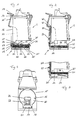
- the device according to FIGS. 1 to 4 has a holder 1, into which a print head 2 is snapped.
- the holder 1 has 10 centering elements in the form of projecting pins 11 on two narrow side walls, in which semicircular recesses 12 of the printhead 2 engage.
- a resilient latching lug 13 is formed, which is latched into a latching shoulder 14 of the head 2.
- the rear wall 15 of the holder 1 has a circular recess 16 which has a rectangular extension 17 at the bottom. Pins 18 protrude from the lateral edges of this extension 17, and slightly more than semicircular recesses 19 of a round flap 20 are snapped onto them.
- the flap 20 also has a rectangular projection 21.
- a sealing lip 23 with a circumferential elastomeric or elastic bead is inserted in a recess 22 on the top of the flap 20, the sealing lip 23 the flap 20 and the head 2 being inserted, the periphery of the nozzle plate 24 of the head 2 is airtight.
- the sealing lip is rectangular. However, other shapes are possible.
- the sealing of the nozzles of the nozzle plate can be ensured for a long time.
- This position of the flap 20 is suitable therefore for shipping the printhead and parking it when not in use so that the ink in the nozzles of the nozzle plates 24 does not dry out.
- an elastomeric plate is expediently placed in the sealing lip 23 for transport, which rests flatly and sealingly on the nozzles.
- the nozzles can also be closed using an adhesive strip.
- a plate 31 designed as a carrier is inserted on the bottom 30 of the holder 1.
- the plate 31 is preferably round. It is snapped into an opening 33 of a spring arm 34 formed on the base 30 with two central hooks 32 projecting downward.
- An absorbent element for cleaning the nozzle plate is inserted in a circular recess 35 in the plate 31.
- it is an elastic disk 36 which is slightly wetted with a cleaning liquid.
- the disk 36 can, for example, consist of an open-cell, elastomeric foam.
- the cleaning liquid mainly consists of water.
- the disk or the foam body 36 can also consist of two layers of different pore sizes, only the lower layer being wetted and the upper layer being dry in the unloaded state.
- the lower layer therefore has greater capillarity (narrower pores). This variant has the advantage that rapid evaporation of the cleaning liquid is prevented.
- the head 2 is first removed from the holder 1, the flap 20 is folded up into the position according to FIG. 2 and the head 2 is reinserted.
- the plate 31 can be pushed up manually (Figure 3), being diametrically opposite the Nozzle plate 24 abuts a stop 37, so that the plate 31 is exactly parallel to the nozzle plate 24.
- the movement of the plate 31 can also be limited on the opposite side by stops, so that the disk 36 is pressed against the nozzle plate 24 with a defined pressure.
- the plate 31 can also be rotated slightly during cleaning.
- the plate 31 is expediently rotated somewhat further between successive cleaning steps.
- the pins 11 allow the plate 31 to rotate freely when the printhead 2 is inserted. If the disk 36 consists of two layers of different porosity, the upper layer is also slightly wetted during compression, which results in better cleaning.
- the head 2 is removed and the flap 20 is folded down so that a projecting edge 38 on the underside of the flap 20 seals against an edge 39 of the plate 31 so that the foam body 36 does not dry out.
- the edge 40 of an opening 41 of the flap 20 engages behind a locking lug 42 of the holder 1.
- the flap 20 is dispensed with.
- the carrier or plate 31 can be rotated in steps and locked in each of these rotational positions with locking elements.
- the latching elements consist of a spring arm 45 integrally formed on the holder 1 with a latching notch 46, into which latching cams 47 engage on the outer circumference of the plate 31.
- the plate 31 is divided into several areas 48.
- the recess 22, in which the sealing lip 23 is fastened, is formed in one of these regions 48.
- foam pads 49 wetted with cleaning fluid are used to clean the nozzle plate.
- the plate 31 has a continuous opening 50 under each of these plates 49.
- a further opening 51 is located in the bottom 30 of the holder 1 below the nozzle plate 24.
- the sealing lip is in the parking and transport position of the plate 31 shown in FIGS. 5 and 6 23 below the nozzle plate 24. If this is to be cleaned, the head 2 is removed from the holder 1, the plate 31 is rotated by one or more steps and the head 2 is reinserted. The foam sheet 49 in question can now be pressed against the nozzle plate 24 through the aligned openings 50, 51 and the latter can thus be cleaned.
- a disk (not shown) which seals against its edge 39 and is sealed above the plate 31 can be fastened to the carrier 1, in which a sector is recessed below the nozzle plate 24.
- the transport lock can be supplemented in accordance with the embodiment according to FIGS. 1 to 3, that is to say a corresponding flap 20 can be provided.
- the plate 31 can be rotated in three positions, namely one for shipping, one for parking and one for cleaning the nozzle plate.
- a lever 52 is formed on the plate 31.
- the sealing lip 23 is attached in a first recess 22. This is used to park the head 2.
- a seal 54 specially designed for transport is used, which, for example, rests over the entire surface of the nozzle plate 24 and closes the nozzles.
- the foam plate 49 is used in the third recess 55 for cleaning the nozzle plate.
- the circumferential sealing lip 23 is inserted directly in the base 30.
- the cleaning element is designed as a cushion 36 and, in addition to the sealing lip 23, is inserted into a recess 60 in the base 30.
- the print head 2 is removed from the holder 1 and a few drops 61 of cleaning liquid are dropped onto the cushion 36.
- the nozzle plate 24 is cleaned by lightly pressing it on and moving it back and forth on the cushion 36 (FIG. 9). If the ink in the nozzles of the nozzle plate 24 should have dried after a long period of non-use, one or two drops of cleaning liquid 61 are placed in the recess 62 of the sealing element 63 enclosed by the sealing lip 23 (FIG.
- the print head 2 is inserted into the holder 1 and upside down ( Figure 11).
- the print head 2 is then removed from the holder 1, the nozzle plate 24 is wiped off on the cushion 36 (FIG. 12) and the print head is reinserted into the holder 1 or directly into the printer.
- the centering elements on the holder 1 for the print head 2 can e.g. be of the same design as in the embodiments according to FIGS. 1 to 6.
- FIGS. 13 and 14 show an embodiment in which a carrier or plate 67 is rotatably inserted into a circular opening 66 in the rear wall 15.
- a cleaning element made of an absorbent material is attached to the plate 67, which is also preferably porous and elastic.
- the cleaning element is attached to a disk 68, for example a sponge, analogously to the disk 36 of the first embodiment.
- the rear has a handle 69 for manually rotating the plate 67.
- the carrier is designed as a slide, which can be pushed back and forth in the vertical direction. It is preferably rectangular.
- FIGS. 13 and 14 can also be provided with the movable supports according to FIGS. 1 to 7.
- this embodiment can also be designed as a holder, which does not have a cleaning element integrated in the holder for cleaning the nozzle plate, but rather only comprises an integrated cleaning element for cleaning the electrical contacts.
- the sealing element 23 effectively protects the nozzles from drying out and from mechanical damage.
- the sealing element 23 can be used interchangeably so that the holder can be used for different printheads.
- the foam body 36 enables a gentle but effective cleaning of the nozzle plate. With heavily dried ink there is also the possibility to treat only the nozzle plate.
- the cleaning pad 36 can be turned over for further use if heavily soiled can be exchanged for a new cleaning pad.
- polishing disk 68 With the polishing disk 68, light oxide layers as well as grease and ink residues on the electrical contacts of the printhead can be quickly removed by simply turning it back and forth.
Landscapes
- Ink Jet (AREA)
Applications Claiming Priority (2)
| Application Number | Priority Date | Filing Date | Title |
|---|---|---|---|
| DE2001135894 DE10135894A1 (de) | 2001-07-24 | 2001-07-24 | Vorrichtung zum Reinigen eines Druckkopfes eines Inkjet-Printers |
| DE10135894 | 2001-07-24 |
Publications (2)
| Publication Number | Publication Date |
|---|---|
| EP1279509A1 true EP1279509A1 (fr) | 2003-01-29 |
| EP1279509B1 EP1279509B1 (fr) | 2009-06-10 |
Family
ID=7692828
Family Applications (1)
| Application Number | Title | Priority Date | Filing Date |
|---|---|---|---|
| EP02405635A Expired - Lifetime EP1279509B1 (fr) | 2001-07-24 | 2002-07-22 | Dispositif de nettoyage d'une tête d'impression d'une imprimante à jet d'encre |
Country Status (2)
| Country | Link |
|---|---|
| EP (1) | EP1279509B1 (fr) |
| DE (2) | DE10135894A1 (fr) |
Citations (6)
| Publication number | Priority date | Publication date | Assignee | Title |
|---|---|---|---|---|
| EP0560729A2 (fr) | 1992-03-10 | 1993-09-15 | Pelikan Produktions Ag | Cartouche d'encre pour tête d'impression d'une imprimante à jet d'encre |
| EP0671273A1 (fr) | 1994-03-10 | 1995-09-13 | Hewlett-Packard Company | Capuchon protecteur pour un dispositif d'écriture par jet d'encre |
| JPH08244247A (ja) | 1995-03-15 | 1996-09-24 | Canon Inc | インクジェットカートリッジ保管箱、およびインクジェット記録装置 |
| DE19609879A1 (de) | 1995-03-13 | 1996-10-02 | Seiko Epson Corp | Lagerbehälter für Tintenstrahldruckeinheit |
| EP0900661A2 (fr) | 1997-09-03 | 1999-03-10 | Hewlett-Packard Company | Récipient de stockage pour cartouches à jet d'encre équipé d'un moyen de nettoyage et procédé de stockage de cartouches à jet d'encre |
| DE20012946U1 (de) | 2000-07-26 | 2000-09-21 | Rena Informationstech Gmbh | Tintenstrahldrucker, insbesondere zur Beschriftung von Versandstücken |
Family Cites Families (1)
| Publication number | Priority date | Publication date | Assignee | Title |
|---|---|---|---|---|
| DE10114541A1 (de) * | 2001-03-21 | 2002-10-02 | Francotyp Postalia Ag | Vorrichtung zum Drucken |
-
2001
- 2001-07-24 DE DE2001135894 patent/DE10135894A1/de not_active Withdrawn
-
2002
- 2002-07-22 EP EP02405635A patent/EP1279509B1/fr not_active Expired - Lifetime
- 2002-07-22 DE DE50213600T patent/DE50213600D1/de not_active Expired - Lifetime
Patent Citations (6)
| Publication number | Priority date | Publication date | Assignee | Title |
|---|---|---|---|---|
| EP0560729A2 (fr) | 1992-03-10 | 1993-09-15 | Pelikan Produktions Ag | Cartouche d'encre pour tête d'impression d'une imprimante à jet d'encre |
| EP0671273A1 (fr) | 1994-03-10 | 1995-09-13 | Hewlett-Packard Company | Capuchon protecteur pour un dispositif d'écriture par jet d'encre |
| DE19609879A1 (de) | 1995-03-13 | 1996-10-02 | Seiko Epson Corp | Lagerbehälter für Tintenstrahldruckeinheit |
| JPH08244247A (ja) | 1995-03-15 | 1996-09-24 | Canon Inc | インクジェットカートリッジ保管箱、およびインクジェット記録装置 |
| EP0900661A2 (fr) | 1997-09-03 | 1999-03-10 | Hewlett-Packard Company | Récipient de stockage pour cartouches à jet d'encre équipé d'un moyen de nettoyage et procédé de stockage de cartouches à jet d'encre |
| DE20012946U1 (de) | 2000-07-26 | 2000-09-21 | Rena Informationstech Gmbh | Tintenstrahldrucker, insbesondere zur Beschriftung von Versandstücken |
Non-Patent Citations (1)
| Title |
|---|
| PATENT ABSTRACTS OF JAPAN vol. 1997, no. 01 31 January 1997 (1997-01-31) * |
Also Published As
| Publication number | Publication date |
|---|---|
| EP1279509B1 (fr) | 2009-06-10 |
| DE10135894A1 (de) | 2003-02-06 |
| DE50213600D1 (de) | 2009-07-23 |
Similar Documents
| Publication | Publication Date | Title |
|---|---|---|
| DE19522593C2 (de) | Vorrichtung zur Reinhaltung der Düsen eines Tintendruckkopfes | |
| DE69628862T2 (de) | Tintenkassette für Tintenstrahldrucker | |
| DE60202797T2 (de) | Tintenstrahldruckkopf und Tintenstrahldrucker | |
| DE69509942T2 (de) | Schutzkappe für einen Tintenstrahlschreiber | |
| DE60316744T2 (de) | Verfahren und Gerät zur Wartung eines Tintenstrahldruckkopfes | |
| DE2725761C2 (de) | Verfahren zum Reinigen oder Spülen der Tintenkanäle bei einem Tintenstrahlschreiber | |
| DE69729424T2 (de) | Tintenstrahlaufzeichnungsgerät | |
| DE3882329T2 (de) | Tintenstrahlschreiber. | |
| DE69216935T2 (de) | Instandsetzungsstelle für Farbstrahldrucker | |
| DE69318513T2 (de) | Tintenstrahldruckerwartungssystem | |
| DE69319065T2 (de) | Reinigungsvorrichtung mit Wischblatt für einen Farbstrahldruckkopf | |
| CH622211A5 (fr) | ||
| EP1503650B1 (fr) | Dispositif de nettoyage pour des sols | |
| EP1681975B1 (fr) | Plaque d'essuyage | |
| DE69611283T2 (de) | Schreibtafel | |
| EP0335914A1 (fr) | Dispositif de nettoyage et de fermeture de la base d'une pointe a ecrire a encre | |
| DE202022101314U1 (de) | Bodenreinigungsgerät mit Schmutzfluid-Tank | |
| DE19522594A1 (de) | Anordnung zur Reinhaltung der Düsen eines Tintendruckkopfes | |
| DE102022102937A1 (de) | Bodenreinigungsgerät mit Schmutzfluid-Tank | |
| EP2121331A1 (fr) | Dispositif pour recharger une cartouche d'encre pour une imprimante à jet d'encre | |
| DE60034653T2 (de) | Abkapselung von Tintenresten auf einer Tintenstrahldruckpatrone | |
| EP1279509B1 (fr) | Dispositif de nettoyage d'une tête d'impression d'une imprimante à jet d'encre | |
| DE19614364A1 (de) | Druckkopf für einen Ink-Jet-Printer | |
| DE3817754A1 (de) | Vorrichtung zum reinigen und verschliessen der duesenflaeche eines tintendruckkopfes | |
| DE102015100537A1 (de) | Handwischer zum manuellen Reinigen von Druckköpfen |
Legal Events
| Date | Code | Title | Description |
|---|---|---|---|
| PUAI | Public reference made under article 153(3) epc to a published international application that has entered the european phase |
Free format text: ORIGINAL CODE: 0009012 |
|
| AK | Designated contracting states |
Designated state(s): AT BE BG CH CY CZ DE DK EE ES FI FR GB GR IE IT LI LU MC NL PT SE SK TR |
|
| AX | Request for extension of the european patent |
Extension state: AL LT LV MK RO SI |
|
| RAP1 | Party data changed (applicant data changed or rights of an application transferred) |
Owner name: PELIKAN HARDCOPY PRODUCTION AG |
|
| 17P | Request for examination filed |
Effective date: 20030718 |
|
| AKX | Designation fees paid |
Designated state(s): CH CZ DE FR GB IT LI |
|
| 17Q | First examination report despatched |
Effective date: 20051214 |
|
| GRAP | Despatch of communication of intention to grant a patent |
Free format text: ORIGINAL CODE: EPIDOSNIGR1 |
|
| GRAS | Grant fee paid |
Free format text: ORIGINAL CODE: EPIDOSNIGR3 |
|
| GRAA | (expected) grant |
Free format text: ORIGINAL CODE: 0009210 |
|
| AK | Designated contracting states |
Kind code of ref document: B1 Designated state(s): CH CZ DE FR GB IT LI |
|
| REG | Reference to a national code |
Ref country code: GB Ref legal event code: FG4D Free format text: NOT ENGLISH |
|
| REG | Reference to a national code |
Ref country code: CH Ref legal event code: EP Ref country code: CH Ref legal event code: PCOW Free format text: PELIKAN HARDCOPY PRODUCTION AG;GEWERBESTRASSE 9;8132 EGG BEI ZUERICH (CH) |
|
| REF | Corresponds to: |
Ref document number: 50213600 Country of ref document: DE Date of ref document: 20090723 Kind code of ref document: P |
|
| PG25 | Lapsed in a contracting state [announced via postgrant information from national office to epo] |
Ref country code: CZ Free format text: LAPSE BECAUSE OF FAILURE TO SUBMIT A TRANSLATION OF THE DESCRIPTION OR TO PAY THE FEE WITHIN THE PRESCRIBED TIME-LIMIT Effective date: 20090610 |
|
| REG | Reference to a national code |
Ref country code: CH Ref legal event code: PL |
|
| PLBE | No opposition filed within time limit |
Free format text: ORIGINAL CODE: 0009261 |
|
| STAA | Information on the status of an ep patent application or granted ep patent |
Free format text: STATUS: NO OPPOSITION FILED WITHIN TIME LIMIT |
|
| REG | Reference to a national code |
Ref country code: FR Ref legal event code: ST Effective date: 20100331 |
|
| PG25 | Lapsed in a contracting state [announced via postgrant information from national office to epo] |
Ref country code: FR Free format text: LAPSE BECAUSE OF NON-PAYMENT OF DUE FEES Effective date: 20090810 Ref country code: CH Free format text: LAPSE BECAUSE OF NON-PAYMENT OF DUE FEES Effective date: 20090731 Ref country code: LI Free format text: LAPSE BECAUSE OF NON-PAYMENT OF DUE FEES Effective date: 20090731 |
|
| 26N | No opposition filed |
Effective date: 20100311 |
|
| GBPC | Gb: european patent ceased through non-payment of renewal fee |
Effective date: 20090910 |
|
| PG25 | Lapsed in a contracting state [announced via postgrant information from national office to epo] |
Ref country code: GB Free format text: LAPSE BECAUSE OF NON-PAYMENT OF DUE FEES Effective date: 20090910 |
|
| PG25 | Lapsed in a contracting state [announced via postgrant information from national office to epo] |
Ref country code: IT Free format text: LAPSE BECAUSE OF FAILURE TO SUBMIT A TRANSLATION OF THE DESCRIPTION OR TO PAY THE FEE WITHIN THE PRESCRIBED TIME-LIMIT Effective date: 20090610 |
|
| PGFP | Annual fee paid to national office [announced via postgrant information from national office to epo] |
Ref country code: DE Payment date: 20110926 Year of fee payment: 10 |
|
| REG | Reference to a national code |
Ref country code: DE Ref legal event code: R082 Ref document number: 50213600 Country of ref document: DE Representative=s name: MEISSNER, BOLTE & PARTNER GBR, DE |
|
| REG | Reference to a national code |
Ref country code: DE Ref legal event code: R082 Ref document number: 50213600 Country of ref document: DE Representative=s name: MEISSNER, BOLTE & PARTNER GBR, DE Effective date: 20120116 Ref country code: DE Ref legal event code: R081 Ref document number: 50213600 Country of ref document: DE Owner name: PELIKAN HARDCOPY PRODUCTION AG, CH Free format text: FORMER OWNER: PELIKAN HARDCOPY PRODUCTION AG, EGG, CH Effective date: 20120116 |
|
| PG25 | Lapsed in a contracting state [announced via postgrant information from national office to epo] |
Ref country code: DE Free format text: LAPSE BECAUSE OF NON-PAYMENT OF DUE FEES Effective date: 20130201 |
|
| REG | Reference to a national code |
Ref country code: DE Ref legal event code: R119 Ref document number: 50213600 Country of ref document: DE Effective date: 20130201 |