EP0561038B1 - Joint pour éléments d'une machine animés dde mouvement alternatif - Google Patents
Joint pour éléments d'une machine animés dde mouvement alternatif Download PDFInfo
- Publication number
- EP0561038B1 EP0561038B1 EP92117662A EP92117662A EP0561038B1 EP 0561038 B1 EP0561038 B1 EP 0561038B1 EP 92117662 A EP92117662 A EP 92117662A EP 92117662 A EP92117662 A EP 92117662A EP 0561038 B1 EP0561038 B1 EP 0561038B1
- Authority
- EP
- European Patent Office
- Prior art keywords
- sealing lips
- seal according
- seal
- groove
- sealing
- Prior art date
- Legal status (The legal status is an assumption and is not a legal conclusion. Google has not performed a legal analysis and makes no representation as to the accuracy of the status listed.)
- Expired - Lifetime
Links
- 238000007789 sealing Methods 0.000 claims description 93
- 239000002861 polymer material Substances 0.000 claims description 2
- 238000000926 separation method Methods 0.000 claims 2
- 238000006073 displacement reaction Methods 0.000 description 4
- 230000000694 effects Effects 0.000 description 4
- 238000009434 installation Methods 0.000 description 3
- 239000000463 material Substances 0.000 description 2
- 230000003313 weakening effect Effects 0.000 description 2
- 230000006866 deterioration Effects 0.000 description 1
- 239000006260 foam Substances 0.000 description 1
- 238000003780 insertion Methods 0.000 description 1
- 230000037431 insertion Effects 0.000 description 1
- 238000004519 manufacturing process Methods 0.000 description 1
- 230000002093 peripheral effect Effects 0.000 description 1
- 230000036316 preload Effects 0.000 description 1
- 230000003068 static effect Effects 0.000 description 1
Images

Classifications
-
- F—MECHANICAL ENGINEERING; LIGHTING; HEATING; WEAPONS; BLASTING
- F16—ENGINEERING ELEMENTS AND UNITS; GENERAL MEASURES FOR PRODUCING AND MAINTAINING EFFECTIVE FUNCTIONING OF MACHINES OR INSTALLATIONS; THERMAL INSULATION IN GENERAL
- F16J—PISTONS; CYLINDERS; SEALINGS
- F16J15/00—Sealings
- F16J15/16—Sealings between relatively-moving surfaces
- F16J15/32—Sealings between relatively-moving surfaces with elastic sealings, e.g. O-rings
- F16J15/3268—Mounting of sealing rings
- F16J15/3272—Mounting of sealing rings the rings having a break or opening, e.g. to enable mounting on a shaft otherwise than from a shaft end
-
- F—MECHANICAL ENGINEERING; LIGHTING; HEATING; WEAPONS; BLASTING
- F16—ENGINEERING ELEMENTS AND UNITS; GENERAL MEASURES FOR PRODUCING AND MAINTAINING EFFECTIVE FUNCTIONING OF MACHINES OR INSTALLATIONS; THERMAL INSULATION IN GENERAL
- F16J—PISTONS; CYLINDERS; SEALINGS
- F16J15/00—Sealings
- F16J15/16—Sealings between relatively-moving surfaces
- F16J15/164—Sealings between relatively-moving surfaces the sealing action depending on movements; pressure difference, temperature or presence of leaking fluid
-
- F—MECHANICAL ENGINEERING; LIGHTING; HEATING; WEAPONS; BLASTING
- F16—ENGINEERING ELEMENTS AND UNITS; GENERAL MEASURES FOR PRODUCING AND MAINTAINING EFFECTIVE FUNCTIONING OF MACHINES OR INSTALLATIONS; THERMAL INSULATION IN GENERAL
- F16J—PISTONS; CYLINDERS; SEALINGS
- F16J15/00—Sealings
- F16J15/16—Sealings between relatively-moving surfaces
- F16J15/32—Sealings between relatively-moving surfaces with elastic sealings, e.g. O-rings
- F16J15/3204—Sealings between relatively-moving surfaces with elastic sealings, e.g. O-rings with at least one lip
- F16J15/3232—Sealings between relatively-moving surfaces with elastic sealings, e.g. O-rings with at least one lip having two or more lips
- F16J15/3236—Sealings between relatively-moving surfaces with elastic sealings, e.g. O-rings with at least one lip having two or more lips with at least one lip for each surface, e.g. U-cup packings
Definitions
- the invention relates to a seal for a reciprocating first machine part, comprising a sealing body made of polymeric material, which is supported in a groove open transversely to the direction of movement of the first machine part on two axially spaced first sealing lips and a second machine part with two axial ones Distance spaced second sealing lips touched under a radial preload, wherein all sealing lips in a flat, imaginary surface that extends perpendicular to the direction of movement of the machine part are assigned in mirror image.
- Such a seal is known from US-A-4 877 257.
- the sealing insert for insertion into a groove has sealing lips which lie on the one hand on the groove base and on the other hand on the surface of the component to be sealed. It should be noted, however, that the assembly of such a sealing insert is unsatisfactory. In particular, in applications in which the installation space for the sealing insert is very small in the axial direction, damage can occur which impair the properties of use during the period of use. If wear occurs, it is difficult to replace the sealing insert.
- the invention has for its object to further develop a seal of the known type such that a significantly simplified assembly results and assembly-related damage can be significantly reduced.
- the first sealing lips are separated from one another by a greater axial distance than the second sealing lips and that the sealing body is provided with a cut at a peripheral point.
- the disassembly and assembly of the sealing body is particularly simple in the case of a sealing body designed in this way, because it is normally not necessary to disassemble the adjacent machine parts.
- the severing means that the sealing body can be elastically expanded in the radial direction and guided over the component to be sealed, for example a piston rod, without it touching the first sealing lips.
- the increased axial distance between the first sealing lips compared to the second sealing lips causes a plate spring effect on the groove base of the first machine part enclosing the sealing ring, as a result of which a particularly good sealing result can be achieved over a long period of use.
- the axial distance between the first sealing lips is two to four times as large as the axial distance between the second sealing lips.
- the second sealing lips lie in the axial direction within the first sealing lips and are reliably pressed by the plate spring action against the surface of the second machine part to be sealed.
- the first sealing lips can be delimited on the sides facing one another by conical surfaces and on the sides facing away from one another by an annular surface.
- the dynamically stressed second sealing lips can be limited on both sides in the axial direction by conical surfaces.
- a comparatively high surface pressure is ensured by the essentially linear sealing on a circumferential circular line of the second machine part to be sealed, as a result of which a reliable sealing is ensured during the entire service life.
- the second sealing lips delimited in the axial direction on both sides by conical surfaces adapt in an excellent manner to the surface properties of the surface to be sealed.
- the first sealing lips can touch the first machine part, which rests relative to the sealing body, each having a cylindrical surface. According to an advantageous embodiment, it is provided that the first sealing lips end at an axial distance from the end faces delimiting the sealing body in the axial direction and that the axial distance and the radial height of the first sealing lips are essentially the same.
- This configuration requires a good service life of the seal due to a dimensionally stable design of the first sealing lips. Even with radial displacements of at least one of the machine parts and the resulting fluctuations in the contact pressure of the first sealing lips on the groove to be sealed, damage to the first sealing lips and a deterioration in the sealing effect cannot be expected.
- a largely uniform utilization of the material of the sealing body is given if the second sealing lips have a radial height which essentially corresponds to the radial height of the first sealing lips. Furthermore, comparatively small dimensions in the radial direction are advantageous here.
- the sealing body can be perforated on at least one end face by at least one groove which extends in the radial direction and is open in the direction of the end face, the groove having an axially measured depth which is not greater than the axial distance between the first sealing lips and the respectively adjacent ones Have end faces. A weakening of the sealing body can thereby be avoided.
- grooves which are evenly distributed in the circumferential direction.
- the grooves which are designed as overflow channels, bring about pressure compensation in the radial direction, so that pressure increases and thus displacements of the sealing body in the radial direction and the resulting leaks are reliably avoided.
- care must be taken that they are arranged on both end faces in such a way that a groove on one axial end face is not opposite a groove on the other axial end face. This precludes excessive weakening of the cross-section.
- At least one groove ends radially on the inside and outside in an opening funnel.
- the sealing body In the area of the severing, the sealing body is provided with two ends which can be hooked into one another in the circumferential direction.
- the assembly is further simplified by this configuration, in particular when the sealing body is arranged in an axially movable piston and seals the medium to be sealed against a housing. Pushing the piston with the assembled sealing body into the housing to be sealed is then particularly simple since the sealing body can no longer spring open in the radial direction.
- the ends are limited only by surfaces extending in the radial direction.
- the manufacture of such a sealing body is particularly simple.
- a further simplification with regard to manufacturability and assembly results if the ends are mirror images of an imaginary radial plane, which is located in the middle of the profile of the sealing body.
- One of the ends can be provided, for example, with a protrusion projecting in the circumferential direction, the cross-section of which is enlarged in the projecting area, the other end having a groove which recesses in the circumferential direction, in which the projection can be latched.
- Various geometric configurations can be provided for this. It is particularly easy to snap the projection into the recessed groove if the ends do not have to be displaced in the radial direction and can be snapped in by a force acting only in the circumferential direction.
- the ends can be delimited axially outside of the groove and the projection by surfaces which extend obliquely to the sealing axis.
- the sealing effect is improved by the surfaces arranged at an angle to the sealing axis and the resulting large gap length.
- the projection and the groove have a profile which, viewed in the radial direction, is essentially circularly delimited. Snapping the projection into the groove is particularly simple, since the circularly delimited ends cause the two ends to be centered in the axial direction relative to one another.
- the groove is elastically widened slightly in the axial direction until the projection is snapped into the groove. A radial displacement of the ends during assembly is therefore unnecessary.
- FIG 1 an embodiment of a sealing body used is shown in a view
- Figure 2 the sealing body is shown in a sectional view, the cross-section can be seen
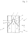
- Figure 3 is a plan view of the sealing body according to Figure 1 in the area Cut shown in which the two ends are hooked together tensile.
- FIGS 3 show a sealing body 1 made of polymer material, which is arranged, for example, in the groove of a piston, not shown here.
- the first two Sealing lips 4, 5 statically seal the radial boundary wall of the groove under radial prestress.
- the two second sealing lips 6, 7 form the dynamic seal, which, for example, sealingly touch the wall of a housing bore under a radially directed prestress.
- the first sealing lips 4, 5 have a greater axial distance from one another than the second sealing lips 6, 7.
- the sealing body 1 is provided with a cut 14 at a circumferential point, as in FIGS 3 shown.
- the first sealing lips 4, 5 are delimited in the area of their bearing surface in the groove by straight surfaces 9 which touch the groove with a circumferentially formed surface 10 in a sealing manner.
- the dynamic sealing by the two second sealing lips 6, 7 takes place essentially along two circumferential lines, the two second sealing lips 6, 7 being delimited on both sides in the axial direction by conical surfaces.
- the first and second sealing lips 4, 5; 6, 7 are arranged in mirror image to an imaginary radial plane running centrally in the axial direction.
- grooves 13 are arranged which run essentially in the radial direction, are uniformly distributed in the circumferential direction and each end in a radial direction on the inside and outside in an orifice funnel.
- FIG. 3 shows the sealing body 1 from FIG. 1 on a greatly enlarged scale.
- the detail shown here shows a top view in the area of the severing 14.
- the two second sealing lips 6, 7 are at such an axial distance from one another that the projection 19 of one End 15 and the groove 20 of the other end 16 are arranged within this axial free space.
- the grooves 13 are arranged in both axial end faces 11, 12.
- the severing 14 is limited by surfaces 22, 23, 24 and 25 which extend obliquely to the sealing axis 21, so that there is a comparatively large gap length. The leakage in a sealing body 1 configured in this way is negligible.
- the projection 19 of one end 15 protruding in the circumferential direction is formed in a three-quarter circle, so that an enlarged cross section results in the projecting area.
- the correspondingly formed, recess 20 in the circumferential direction of the other end 16 is also substantially circular.
- This configuration offers the advantage that assembly in the groove, for example of a piston, can be carried out particularly easily.
- the two ends 15, 16 are hooked into one another only by a movement in the circumferential direction towards one another. A radial displacement of the ends 15, 16 to one another is unnecessary.
- the projection 19 is snapped into the correct position by the centering effect and the roof-shaped severing viewed in the circumferential direction.
- the severing 14 is carried out in such a way that it begins in the region of the end faces 11, 12 at the location of the greatest axial extent. This results in a good sealing result over a long period of use combined with simple installation.
Landscapes
- Engineering & Computer Science (AREA)
- General Engineering & Computer Science (AREA)
- Mechanical Engineering (AREA)
- Sealing Devices (AREA)
Claims (16)
- Joint pour un premier élément d'une machine animé d'un mouvement alternatif, comprenant un corps d'étanchéité (1) en matière polymère qui est appuyé, dans une gorge ouverte transversalement à la direction du mouvement du premier élément d'une machine, sur deux premières lèvres d'étanchéité (4, 5) présentant une distance axiale et qui est en contact, et mis en prétension, avec un deuxième élément d'une machine avec deux secondes lèvres d'étanchéité (6, 7) présentant une distance axiale, toutes les lèvres d'étanchéité étant disposées de manière symétrique inversée dans une surface plane imaginaire qui s'étend perpendiculairement à la direction du mouvement de l'élément de la machine, caractérisé en ce que les premières lèvres d'étanchéité (4, 5) sont séparées l'une de l'autre par une distance axiale supérieure à celle des secondes lèvres d'étanchéité (6, 7) et en ce que le corps d'étanchéité (1) présente, à un endroit de sa circonférence, une séparation (14).
- Joint selon la revendication 1, caractérisé en ce que la distance axiale entre les premières lèvres d'étanchéité (4, 5) est deux à quatre fois plus grande que la distance axiale entre les secondes lèvres d'étanchéité (6, 7).
- Joint selon l'un des revendications 1 et 2, caractérisé en ce que les premières lèvres d'étanchéité (4, 5) sont limitées, sur les côtés tournés l'un vers l'autre, par une surface conique (8) et, sur les côtés éloignés l'un de l'autre, par une surface en forme d'anneau de cercle.
- Joint selon l'une des revendications 1 à 3, caractérisé en ce que les secondes lèvres d'étanchéité (6, 7) sont limitées, sur les deux côtés dans la direction axiale, par des surfaces coniques (8).
- Joint selon l'une des revendications 1 à 4, caractérisé en ce que les premières lèvres d'étanchéité (4, 5) touchent le premier élément d'une machine avec une surface (10) exécutée de manière cylindrique.
- Joint selon l'une des revendications 1 à 5, caractérisé en ce que les premières lèvres d'étanchéité (4, 5) se terminent à une distance axiale des surfaces frontales (11, 12) limitant le corps d'étanchéité (1) dans la direction axiale et en ce que cette distance axiale coïncide sensiblement avec la hauteur radiale des premières lèvres d'étanchéité (4, 5).
- Joint selon la revendication 6, caractérisé en ce que les secondes lèvres d'étanchéité (6, 7) ont une hauteur radiale qui concorde sensiblement avec la hauteur radiale des premières lèvres d'étanchéité (4, 5).
- Joint selon l'une des revendications 6 à 7, caractérisé en ce que le corps d'étanchéité (1) est traversé, sur au moins une surface frontale (11, 12), par au moins une gorge (13) ouverte en direction de la surface frontale (11, 12) et s'étendant dans la direction radiale, et en ce que la gorge (13) a une profondeur, mesurée dans le sens axial, qui n'est pas supérieure à la distance axiale existant entre les premières lèvres d'étanchéité et la surface frontale respective qui leur est contiguë.
- Joint selon la revendication 8, caractérisé en ce que plusieurs gorges (13) sont prévues et que les gorges (13) sont réparties de manière régulière dans la direction circonférentielle.
- Joint selon l'une des revendications 8 à 9, caractérisé en ce qu'il est prévu au moins une gorge (13) qui se termine, sur le côté intérieur et sur le côté extérieur dans le sens radial, de manière semblable à un entonnoir formant une embouchure.
- Joint selon l'une des revendications 1 à 10, caractérisé en ce que le corps d'étanchéité (1) est pourvu, dans la région de la séparation (14), de deux extrémités (15, 16) qui peuvent être accrochées l'une dans l'autre d'une manière résistant à la traction dans la direction circonférentielle.
- Joint selon la revendication 11, caractérisé en ce que les extrémités (15, 16) sont limitées exclusivement par des surfaces (17, 18) s'étendant dans la direction radiale.
- Joint selon l'une des revendications 11 à 12, caractérisé en ce que les extrémités (15, 16) sont exécutées de manière symétrique inversée par rapport à un plan radial imaginaire qui se trouve au milieu du profil du corps d'étanchéité (1).
- Joint selon la revendication 13, caractérisé en ce que l'une des extrémités (15, 16) est pourvue d'une saillie (19) saillant dans la direction circonférentielle et dont la section transversale est élargie dans la région saillante, et en ce que l'autre extrémité (16, 15) est pourvue d'une gorge (20) rentrant en arrière dans la direction circonférentielle et dans laquelle la saillie (19) peut s'enclencher.
- Joint selon l'une des revendications 11 à 14, caractérisé en ce que les extrémités (15, 16) sont limitées, à l'extérieur de la gorge (20) et de la saillie, dans le sens axial, par des surfaces (22, 23, 24, 25) qui s'étendent de manière oblique par rapport à l'axe (21) du joint.
- Joint selon l'une des revendications 14 à 15, caractérisé en ce que la saillie (19) et la gorge (20) ont un profil qui, considéré dans la direction radiale, est limité de manière sensiblement circulaire.
Applications Claiming Priority (2)
| Application Number | Priority Date | Filing Date | Title |
|---|---|---|---|
| DE4208373A DE4208373C2 (de) | 1992-03-16 | 1992-03-16 | Dichtung für ein hin- und hergehendes Maschinenteil |
| DE4208373 | 1992-03-16 |
Publications (2)
| Publication Number | Publication Date |
|---|---|
| EP0561038A1 EP0561038A1 (fr) | 1993-09-22 |
| EP0561038B1 true EP0561038B1 (fr) | 1995-07-19 |
Family
ID=6454184
Family Applications (1)
| Application Number | Title | Priority Date | Filing Date |
|---|---|---|---|
| EP92117662A Expired - Lifetime EP0561038B1 (fr) | 1992-03-16 | 1992-10-16 | Joint pour éléments d'une machine animés dde mouvement alternatif |
Country Status (2)
| Country | Link |
|---|---|
| EP (1) | EP0561038B1 (fr) |
| DE (2) | DE4208373C2 (fr) |
Families Citing this family (1)
| Publication number | Priority date | Publication date | Assignee | Title |
|---|---|---|---|---|
| EP2360089A1 (fr) * | 2010-02-23 | 2011-08-24 | Single Buoy Moorings Inc. | Rotule pour fluide permettant le transfert de fluide sur l'interface rotative |
Family Cites Families (14)
| Publication number | Priority date | Publication date | Assignee | Title |
|---|---|---|---|---|
| DE7312719U (de) * | 1973-12-13 | Duerkoppwerke Gmbh | Spielfreies Radialwälzlager | |
| DE7103292U (de) * | 1971-07-29 | Continental Gummi Werke Ag | Dichtung für Wellenlager | |
| DE822095C (de) * | 1948-11-22 | 1951-11-22 | Isothermos Soc Gen | Staubdichtung fuer Achslagerkaesten von Schienenfahrzeugen |
| US3245693A (en) * | 1964-06-05 | 1966-04-12 | David G Way | Sealing rings |
| US3325175A (en) * | 1965-02-05 | 1967-06-13 | Dodge Mfg Corp | Shaft seal with multiple lips |
| GB1148885A (en) * | 1965-08-14 | 1969-04-16 | Pioneer Oilsealing & Moulding | Improvements in and relating to sealing rings |
| DE1943177A1 (de) * | 1968-08-27 | 1970-05-21 | Ferderal Mogul Corp | Radiale Wellendichtung fuer Kurbelwellen od.dgl. |
| GB1492539A (en) * | 1973-12-29 | 1977-11-23 | Polypac Bal Ltd | Packing assemblies |
| DE3130760A1 (de) * | 1981-08-04 | 1983-02-24 | Robert Bosch Gmbh, 7000 Stuttgart | Dichtungsanordnung |
| DE3207327A1 (de) * | 1982-03-01 | 1983-09-08 | Heinz Konrad Prof. Dr.-Ing. 7050 Waiblingen Müller | Wellendichtung |
| DE3316767A1 (de) * | 1983-05-07 | 1984-12-06 | Kolbenschmidt AG, 7107 Neckarsulm | Platine zur herstellung gerollter buchsen fuer gleitlager |
| DE3509840C2 (de) * | 1985-03-19 | 1987-05-14 | Fa. Carl Freudenberg, 6940 Weinheim | Dichtring |
| US4877257A (en) * | 1987-08-19 | 1989-10-31 | Ide Russell D | Piston ring |
| FR2623589B1 (fr) * | 1987-11-23 | 1990-01-26 | Guinard Pompes | Garniture d'etancheite |
-
1992
- 1992-03-16 DE DE4208373A patent/DE4208373C2/de not_active Expired - Lifetime
- 1992-10-16 EP EP92117662A patent/EP0561038B1/fr not_active Expired - Lifetime
- 1992-10-16 DE DE59202956T patent/DE59202956D1/de not_active Expired - Fee Related
Also Published As
| Publication number | Publication date |
|---|---|
| DE59202956D1 (de) | 1995-08-24 |
| EP0561038A1 (fr) | 1993-09-22 |
| DE4208373C2 (de) | 1994-12-08 |
| DE4208373A1 (de) | 1993-09-23 |
Similar Documents
| Publication | Publication Date | Title |
|---|---|---|
| DE60133449T2 (de) | Fluidfilter und ein Fluidfilter-Filterkopf-Gerät | |
| EP0774568A1 (fr) | Dispositif d'étanchéité | |
| DE19739472A1 (de) | Dichtungsanordnung | |
| EP0557579A1 (fr) | Dispositif d'étanchéité | |
| DE19728605C2 (de) | Stangen- oder Kolbendichtung | |
| DE102013012044B4 (de) | Dichtungsanordnung und Dichtring | |
| EP0798498B1 (fr) | Joint à lèvre radiale avec effet de refoulement indépendant du sens de rotation | |
| DE3016231C2 (de) | Dichtungsanordnung | |
| EP0832382B1 (fr) | Bague d'etancheite pour milieu gazeux | |
| EP0561038B1 (fr) | Joint pour éléments d'une machine animés dde mouvement alternatif | |
| EP0412997B1 (fr) | Garniture d'etancheite | |
| DE102014014033A1 (de) | Dichtring und Dichtungsanordnung, die den Dichtring umfasst | |
| DE19726433C2 (de) | Dichtungsanordnung | |
| EP1055849B1 (fr) | Joint d'étanchéité pour chambres sous pression | |
| EP0660015B1 (fr) | Dispositif d'étanchéité pour deux pièces de machine mobiles en translation l'une relativement par rapport à l'autre | |
| DE4317483A1 (de) | Kolben, insbesondere für den Servozylinder einer Hilfskraftlenkanlage | |
| DE19936462B4 (de) | Abstreifring | |
| DE102019202130B4 (de) | Dichtungsanordnung | |
| EP3511590B1 (fr) | Joint d'étanchéité et dispositif d'étanchéité comprenant le joint d'étanchéité | |
| EP0724097B1 (fr) | Dispositif d'étanchéité | |
| EP1798454B1 (fr) | Anneau d'étanchéité ainsi que dispositif d'étanchéité utilisant cet anneau | |
| DE69623201T2 (de) | Dichtungsvorrichtung | |
| EP4317749B1 (fr) | Ensemble joint et appareil de traitement d'eau comprenant l'ensemble joint | |
| EP1388694B1 (fr) | Dispositif d'étanchéité | |
| EP1248025B1 (fr) | Joint d'étanchéité |
Legal Events
| Date | Code | Title | Description |
|---|---|---|---|
| PUAI | Public reference made under article 153(3) epc to a published international application that has entered the european phase |
Free format text: ORIGINAL CODE: 0009012 |
|
| 17P | Request for examination filed |
Effective date: 19930630 |
|
| AK | Designated contracting states |
Kind code of ref document: A1 Designated state(s): DE FR GB IT SE |
|
| RAP3 | Party data changed (applicant data changed or rights of an application transferred) |
Owner name: FIRMA CARL FREUDENBERG |
|
| 17Q | First examination report despatched |
Effective date: 19950111 |
|
| GRAA | (expected) grant |
Free format text: ORIGINAL CODE: 0009210 |
|
| AK | Designated contracting states |
Kind code of ref document: B1 Designated state(s): DE FR GB IT SE |
|
| REF | Corresponds to: |
Ref document number: 59202956 Country of ref document: DE Date of ref document: 19950824 |
|
| ET | Fr: translation filed | ||
| GBT | Gb: translation of ep patent filed (gb section 77(6)(a)/1977) |
Effective date: 19950812 |
|
| ITF | It: translation for a ep patent filed | ||
| PLBE | No opposition filed within time limit |
Free format text: ORIGINAL CODE: 0009261 |
|
| STAA | Information on the status of an ep patent application or granted ep patent |
Free format text: STATUS: NO OPPOSITION FILED WITHIN TIME LIMIT |
|
| 26N | No opposition filed | ||
| REG | Reference to a national code |
Ref country code: GB Ref legal event code: IF02 |
|
| PGFP | Annual fee paid to national office [announced via postgrant information from national office to epo] |
Ref country code: GB Payment date: 20030925 Year of fee payment: 12 |
|
| PGFP | Annual fee paid to national office [announced via postgrant information from national office to epo] |
Ref country code: FR Payment date: 20031022 Year of fee payment: 12 |
|
| PG25 | Lapsed in a contracting state [announced via postgrant information from national office to epo] |
Ref country code: GB Free format text: LAPSE BECAUSE OF NON-PAYMENT OF DUE FEES Effective date: 20041016 |
|
| GBPC | Gb: european patent ceased through non-payment of renewal fee |
Effective date: 20041016 |
|
| PG25 | Lapsed in a contracting state [announced via postgrant information from national office to epo] |
Ref country code: FR Free format text: LAPSE BECAUSE OF NON-PAYMENT OF DUE FEES Effective date: 20050630 |
|
| REG | Reference to a national code |
Ref country code: FR Ref legal event code: ST |
|
| PGFP | Annual fee paid to national office [announced via postgrant information from national office to epo] |
Ref country code: DE Payment date: 20081103 Year of fee payment: 17 |
|
| PGFP | Annual fee paid to national office [announced via postgrant information from national office to epo] |
Ref country code: SE Payment date: 20081023 Year of fee payment: 17 Ref country code: IT Payment date: 20081022 Year of fee payment: 17 |
|
| EUG | Se: european patent has lapsed | ||
| PG25 | Lapsed in a contracting state [announced via postgrant information from national office to epo] |
Ref country code: DE Free format text: LAPSE BECAUSE OF NON-PAYMENT OF DUE FEES Effective date: 20100501 |
|
| PG25 | Lapsed in a contracting state [announced via postgrant information from national office to epo] |
Ref country code: IT Free format text: LAPSE BECAUSE OF NON-PAYMENT OF DUE FEES Effective date: 20091016 |
|
| PG25 | Lapsed in a contracting state [announced via postgrant information from national office to epo] |
Ref country code: SE Free format text: LAPSE BECAUSE OF NON-PAYMENT OF DUE FEES Effective date: 20091017 |