EP1388694B1 - Dispositif d'étanchéité - Google Patents
Dispositif d'étanchéité Download PDFInfo
- Publication number
- EP1388694B1 EP1388694B1 EP03015408A EP03015408A EP1388694B1 EP 1388694 B1 EP1388694 B1 EP 1388694B1 EP 03015408 A EP03015408 A EP 03015408A EP 03015408 A EP03015408 A EP 03015408A EP 1388694 B1 EP1388694 B1 EP 1388694B1
- Authority
- EP
- European Patent Office
- Prior art keywords
- sealing
- sealing ring
- arrangement according
- connecting device
- ring
- Prior art date
- Legal status (The legal status is an assumption and is not a legal conclusion. Google has not performed a legal analysis and makes no representation as to the accuracy of the status listed.)
- Expired - Lifetime
Links
- 238000007789 sealing Methods 0.000 title claims abstract description 174
- 239000000463 material Substances 0.000 claims abstract description 25
- 239000013536 elastomeric material Substances 0.000 claims description 10
- 239000004810 polytetrafluoroethylene Substances 0.000 claims description 7
- 229920001343 polytetrafluoroethylene Polymers 0.000 claims description 7
- 238000010276 construction Methods 0.000 abstract description 3
- 229920000642 polymer Polymers 0.000 abstract 1
- 230000002787 reinforcement Effects 0.000 abstract 1
- 238000007599 discharging Methods 0.000 description 3
- 238000004519 manufacturing process Methods 0.000 description 3
- 230000001681 protective effect Effects 0.000 description 3
- 150000001875 compounds Chemical class 0.000 description 2
- 239000000498 cooling water Substances 0.000 description 2
- 230000001419 dependent effect Effects 0.000 description 2
- 238000004064 recycling Methods 0.000 description 2
- 238000000926 separation method Methods 0.000 description 2
- 230000003319 supportive effect Effects 0.000 description 2
- 229910000639 Spring steel Inorganic materials 0.000 description 1
- 230000000712 assembly Effects 0.000 description 1
- 238000000429 assembly Methods 0.000 description 1
- 238000005516 engineering process Methods 0.000 description 1
- 238000009434 installation Methods 0.000 description 1
- 230000001050 lubricating effect Effects 0.000 description 1
- 239000002184 metal Substances 0.000 description 1
- 239000007769 metal material Substances 0.000 description 1
- 230000002093 peripheral effect Effects 0.000 description 1
- 239000004033 plastic Substances 0.000 description 1
- 125000006850 spacer group Chemical group 0.000 description 1
- 238000011144 upstream manufacturing Methods 0.000 description 1
Images
Classifications
-
- F—MECHANICAL ENGINEERING; LIGHTING; HEATING; WEAPONS; BLASTING
- F16—ENGINEERING ELEMENTS AND UNITS; GENERAL MEASURES FOR PRODUCING AND MAINTAINING EFFECTIVE FUNCTIONING OF MACHINES OR INSTALLATIONS; THERMAL INSULATION IN GENERAL
- F16J—PISTONS; CYLINDERS; SEALINGS
- F16J15/00—Sealings
- F16J15/16—Sealings between relatively-moving surfaces
- F16J15/32—Sealings between relatively-moving surfaces with elastic sealings, e.g. O-rings
- F16J15/3204—Sealings between relatively-moving surfaces with elastic sealings, e.g. O-rings with at least one lip
- F16J15/3228—Sealings between relatively-moving surfaces with elastic sealings, e.g. O-rings with at least one lip formed by deforming a flat ring
-
- F—MECHANICAL ENGINEERING; LIGHTING; HEATING; WEAPONS; BLASTING
- F16—ENGINEERING ELEMENTS AND UNITS; GENERAL MEASURES FOR PRODUCING AND MAINTAINING EFFECTIVE FUNCTIONING OF MACHINES OR INSTALLATIONS; THERMAL INSULATION IN GENERAL
- F16J—PISTONS; CYLINDERS; SEALINGS
- F16J15/00—Sealings
- F16J15/002—Sealings comprising at least two sealings in succession
- F16J15/004—Sealings comprising at least two sealings in succession forming of recuperation chamber for the leaking fluid
Definitions
- the invention relates to a sealing arrangement, comprising a first and a second sealing ring, which are assigned to each other axially adjacent and captively connected to each other, wherein at least the first sealing ring self-supporting, i. is formed Stützterrorism and consists of polymeric material, wherein both sealing rings on the facing sides each having a connecting device and wherein the connecting means of the first sealing ring is formed integrally and of the same material therewith, wherein the first and the second sealing ring each at least one dynamically stressed during operation Have sealing lip, wherein the sealing lips are arranged adjacent to each other at an axial distance and wherein the sealing lips are sealingly applied with radial bias to the surface of a machine element to be sealed and define a cavity in the axial direction.
- Such a sealing arrangement is known from US 4,053,166.
- the previously known sealing arrangement is translationally to seal off and herbewegbarer machine elements provided, wherein the sealing rings are arranged in a functional series connection.
- the two sealing rings each enclose with a dynamically stressed sealing lip the surface of a reciprocating rod to be sealed, wherein the sealing ring facing the space to be sealed is comparatively softer and consists of an elastomeric material.
- relatively harder sealing ring is arranged, which consists for example of PTFE.
- the connecting device of the two sealing rings is in each case formed in one piece and of the same material with the respective sealing ring, wherein one of the sealing rings has a projection and the other sealing ring has a congruently designed recess and wherein the projection and the recess are positively connected with each other.
- the sealing lip of the relatively harder sealing ring is designed as a support body for the sealing lip of the comparatively softer sealing ring, so that the sealing lip of the softer sealing ring works even with relatively large pressurization. Even with large pressurization of the seal arrangement, the friction is not undesirably high, since the comparatively harder sealing ring, which is designed as a support ring for the softer sealing ring, consists of PTFE.
- connection which connects the cavity with the environment, is largely dependent on the assembly of the seal assembly; Depending on the accuracy with which the assembly is made, the geometric dimensions of the connection differ.
- the connection is limited axially by the two back-mounted seals.
- the previously known sealing arrangement is used as a cooling water pump seal for use and comprises a main seal, the cooling water side, a protective seal is connected upstream.
- the protective seal consists of a filter fleece and is held on the outside in a plastic support body. This support body of the protective seal is fixed by a plug connection to a support body of the main seal.
- the invention has the object of providing a seal assembly of the type mentioned in such a way that it has a simple and low-part construction and therefore in manufacturing technology and economic terms is simple and inexpensive to produce and that leakage from this area safely dissipated to the environment and an undesirable Pressure build-up is avoided axially between the sealing lips.
- a sealing arrangement comprising a first and a second sealing ring, which axially adjacent to each other assigned and captive are connected to each other, wherein at least the first sealing ring is self-supporting, ie consists of supportive material and consists of polymeric material, both sealing rings on the facing sides each having a connecting device and wherein the connecting means of the first sealing ring is formed integrally and of the same material with this wherein the first and the second sealing ring each have at least one dynamically stressed during operation sealing lip, wherein the sealing lips are arranged adjacent to each other at an axial distance and wherein the sealing lips with radial bias sealingly against the surface of a sealed machine element can be applied and in the axial direction a cavity limit and wherein at least one of the sealing rings in the region axially between the sealing lips at least one recess which forms a part of the connecting device, which has the cavity for discharging v on leakage connects with the environment.
- the non-supporting first sealing ring is formed in one piece and of uniform material and consists for example of a PTFE compound.
- the material is selected such that on the one hand it enables a good sealing of the space to be sealed from the environment and on the other hand a durable connecting device which cooperates with the connecting device of the second sealing ring.
- the one-piece, uniform material first sealing ring is also in terms of a simple, unmixed recycling oftownzurioldem advantage. A separation of different materials prior to recycling, which must be performed, for example, in sealing rings with a support body made of a metallic material, it is not required.
- the first and the second sealing ring each have at least one dynamically stressed sealing lip, wherein the sealing lips are arranged adjacent to each other at an axial distance and wherein the sealing lips with radial bias sealing to the surface of a machine element to be sealed can be applied and limit a cavity in the axial direction.
- Such an arrangement has proven particularly useful when the sealing arrangement for the separation of difficult or incompatible media is used, wherein the media, for example, have a different lubricating characteristic.
- the seal arrangement can be used, for example, in tandem pumps.
- At least one of the sealing rings has at least one recess in the region between the sealing lips, which connects the cavity for discharging leakage with the environment. This ensures that operationally occurring leakage within the cavity does not lead to an undesirable pressure build-up between the sealing lips and thereby undesirable negative performance characteristics over a longer period.
- the leakage is discharged from the cavity into the environment and indicates that at least one of the sealing rings is worn / damaged and therefore has to be replaced. The discharged into the environment leakage is therefore an indicator of the functionality / the state of the seal assembly.
- the second sealing ring is made entirely of elastomeric material and that the connecting device of the second sealing ring is formed integrally and with the same material.
- the second sealing ring is self-supporting, ie trained supportive body.
- Such a sealing arrangement with two sealing rings then consists entirely of only two divergent materials, namely a polymeric material of which the first sealing ring is made and an elastomeric material of which the second sealing ring is made.
- the second sealing ring comprises a support body of tough material, which is at least partially enclosed by a jacket made of elastomeric material, wherein the connecting means of the second sealing ring is formed integrally and of the same material with the jacket.
- the support ring may for example consist of a polymeric material or of a thermoformed sheet.
- a second sealing ring with supporting body is particularly useful when the second sealing ring is pressed into a bore of a housing and to seal the bore of the housing relative to the environment statically.
- a dynamically stressed sealing lip may be formed, which consists of elastomeric material and eiri Kunststoffig and is formed of the same material with the jacket. The sealing lip can be pressed against the surface of the machine element to be sealed, for example, by an annular helical spring.
- the connecting means of one of the sealing rings can be formed by at least one locking cam-shaped projection and the connecting means of the other sealing ring by an undercut recess, wherein the projection and the recess are snapped into each other.
- Such locking cam-shaped connecting devices are easy to manufacture and assemble. Assembly errors in the connection of the two sealing rings are thereby limited to a minimum.
- the sealing rings Due to the locking cam-shaped connection of the two sealing rings with each other, they are non-destructively releasably connected to each other in a simple manner. This is advantageous in that the sealing rings, depending on the respective wear, are each separately exchangeable. Thus, for example, it is possible to replace the existing of an elastomeric material second sealing ring because of its relatively higher wear at undesirably high leakage and the relatively wear-resistant continue to use the first sealing ring together with the new, replaced second sealing ring.
- first sealing ring and the second sealing ring can be positively and / or positively connected to each other by the connecting means.
- the first and the second sealing ring preferably form a preassemblable unit, so that assembly errors in the assembly of the seal assembly are limited in their installation space to a minimum.
- the sealing lips of the sealing rings in each case in the axial direction against the adjacent sealing ring be bulged axially in the direction of each space to be sealed.
- the first sealing ring may have a radially open groove for receiving a separately generated, statically stressed seal on the side facing away from its sealing lip radially. If, for example, a shaft is sealed by the sealing arrangement, the dynamically stressed sealing lips seal the surface of the shaft to be sealed under elastic prestressing.
- the groove is open radially outward in such a case, wherein in the groove, for example, an O-ring is arranged, which seals the outer peripheral side enclosing a housing seal statically relative to the environment.
- the first sealing ring consists essentially of PTFE.
- PTFE is resistant to most media to be sealed. Even during an extremely long service life is subject to a sealing ring made of such a material only a negligible, abrasive wear, so that the seal assembly has consistently good performance for a long service life.
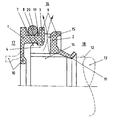
- FIGS. 1 and 2 each show a sealing arrangement which consists of a first sealing ring 1 and a second sealing ring 2.
- the seal assembly with the two sealing rings 1, 2 is intended for use in a tandem pump and seals heavy or incompatible media against each other.
- the two sealing rings 1, 2 are associated axially adjacent to one another and each have a dynamically stressed sealing lip 10, 11, wherein the sealing lips 10, 11 are associated with each other adjacent to an axial spacing.
- the sealing arrangements are each shown in the production-related, non-installed state.
- a machine element to be sealed 13 is shown in dashed lines, as well as the mounting-related shape of the sealing lip 10 of the first sealing ring. 1
- the sealing lips 10, 11 enclose the surface 12 of the machine element 13 to be sealed under elastic prestress and limit a cavity 14 in the axial direction.
- the sealing lips 10, 11 are bulged axially in the direction of the respective space 17, 18 to be sealed.
- the second sealing ring 2 has at least one recess 15, which is arranged at the lowest point of the sealing arrangement. From the spaces to be sealed 1.7, 18 leaking leakage passes through the recess 15 in the environment 16 and thereby indicates that at least one of the sealing rings 1, 2 must be replaced.
- the recess 15 may alternatively be arranged in the first sealing ring 1.
- the recess 15 may comprise two partial areas, one of which forms part of the first sealing ring 1 and the other forms part of the second sealing ring 2.
- the recess 15 preferably forms part of the connecting means 3, 4, in the embodiments shown here forms part of the connecting means 4 of the second sealing ring 2. Also by the additional function of the connecting device 4 as a recess 15 for removing leakage from the cavity 14 into the environment 16, the sealing arrangements shown here have a simple and low-part construction.
- the first sealing ring 1 is made of a PTFE compound and is self-supporting, ie formed without support body.
- the connecting device 3 of the first sealing ring 1 is integrally formed and of the same material with this.
- FIG. 1 shows a first exemplary embodiment of the sealing arrangement.
- the second sealing ring 2 is made entirely of elastomeric material.
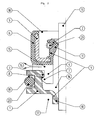
- a second sealing ring 2 is shown in the embodiment of Figure 2, comprising a support body 5 made of sheet metal, which is enclosed by the jacket 6 made of elastomeric material.
- the sealing lip 11 of the second sealing ring 2 is pressed by the ring helical spring 21, which consists of spring steel, to the surface 12 of the machine element 13 to be sealed.
- the connecting device 4 provided with the recess 15 is provided with a circumferentially encircling, locking cam-shaped projection 7 which is snapped into the annular, undercut recess 8 of the first sealing ring 1.
- the first and second sealing ring 2 are non-destructively releasably connected to each other and thereby, if necessary, separately exchangeable.
Landscapes
- Engineering & Computer Science (AREA)
- General Engineering & Computer Science (AREA)
- Mechanical Engineering (AREA)
- Sealing Devices (AREA)
- Sealing With Elastic Sealing Lips (AREA)
- Gasket Seals (AREA)
- Connector Housings Or Holding Contact Members (AREA)
Claims (10)
- Dispositif d'étanchéité, comprenant un premier (1) et un deuxième (2) anneaux d'étanchéité, qui sont associés à proximité axiale l'un de l'autre et qui sont assemblés l'un à l'autre de manière imperdable, au moins le premier anneau d'étanchéité (1) étant autoporteur, c'est-à-dire qu'il est réalisé sans corps de support et qu'il se compose d'un matériau polymère, les deux anneaux d'étanchéité (1, 2) présentant chacun un dispositif d'assemblage (3, 4) sur les côtés tournés l'un vers l'autre et le dispositif d'assemblage (3) du premier anneau d'étanchéité (1) étant réalisé en une seule pièce et en une seule matière avec celui-ci, le premier (1) et le deuxième (2) anneaux d'étanchéité présentant respectivement au moins une lèvre d'étanchéité (10, 11) sollicitée dynamiquement en fonctionnement, les lèvres d'étanchéité (10, 11) étant disposées à proximité l'une de l'autre avec une distance axiale et les lèvres d'étanchéité (10, 11) pouvant être appliquées hermétiquement avec une précontrainte radiale sur la surface (12) d'un élément de machine (13) à rendre étanche et délimitant un espace creux (14) en direction axiale, caractérisé en ce qu'au moins un des anneaux d'étanchéité (2) présente, dans la région située axialement entre les lèvres d'étanchéité (10, 11), au moins un évidemment (15) qui forme un composant du dispositif d'assemblage (4), qui relie l'espace creux (14) avec l'atmosphère (16) pour l'évacuation de fuites.
- Dispositif d'étanchéité selon la revendication 1, caractérisé en ce que le deuxième anneau d'étanchéité (2) se compose entièrement d'un matériau élastomère et en ce que le dispositif d'assemblage (4) du deuxième anneau d'étanchéité (2) est réalisé en une seule pièce et en une seule matière avec celui-ci.
- Dispositif d'étanchéité selon la revendication 1, caractérisé en ce que le deuxième anneau d'étanchéité (2) comprend un corps de support (5) en un matériau ductile dur, qui est entouré au moins en partie par une enveloppe (6) en un matériau élastomère et en ce que le dispositif d'assemblage (4) du deuxième anneau d'étanchéité (2) est réalisé en une seule pièce et en une seule matière avec l'enveloppe (6).
- Dispositif d'étanchéité selon l'une quelconque des revendications 1 à 3, caractérisé en ce que le dispositif d'assemblage (4) d'un des anneaux d'étanchéité (2) est formé par au moins une saillie (7) en forme d'ergot d'encliquetage et le dispositif d'assemblage (3) de l'autre anneau d'étanchéité (1) est formé par un évidement en contre-dépouille (8), et en ce que la saillie (7) et l'évidement (8) peuvent être encliquetés l'un dans l'autre.
- Dispositif d'étanchéité selon l'une quelconque des revendications 1 à 4, caractérisé en ce que le premier (1) et le deuxième (2) anneaux d'étanchéité sont assemblés l'un à l'autre de façon séparable sans dommages.
- Dispositif d'étanchéité selon l'une quelconque des revendications 1 à 5, caractérisé en ce que le premier anneau d'étanchéité (1) et le deuxième anneau d'étanchéité (2) sont assemblés l'un à l'autre, en continuité de force et/ou de forme, par les dispositifs d'assemblage (3, 4).
- Dispositif d'étanchéité selon l'une quelconque des revendications 1 à 6, caractérisé en ce que le premier (1) et le deuxième (2) anneaux d'étanchéité forment une unité (9) pouvant être préassemblée.
- Dispositif d'étanchéité selon l'une quelconque des revendications 1 à 7, caractérisé en ce que les lèvres d'étanchéité (10, 11) des anneaux d'étanchéité (1, 2) sont précintrées axialement en direction de chaque espace à rendre étanche (17, 18), chaque fois en direction axiale opposée à l'anneau d'étanchéité voisin (2, 1).
- Dispositif d'étanchéité selon l'une quelconque des revendications 1 à 8, caractérisé en ce que le premier anneau d'étanchéité (1) présente, sur le côté radialement opposé à sa lèvre d'étanchéité (10), une rainure ouverte radialement (19), destinée à recevoir un joint d'étanchéité (20) produit séparément, sollicité statiquement.
- Dispositif d'étanchéité selon l'une quelconque des revendications 1 à 9, caractérisé en ce que le premier anneau d'étanchéité (1) se compose essentiellement de PTFE.
Applications Claiming Priority (2)
| Application Number | Priority Date | Filing Date | Title |
|---|---|---|---|
| DE10236831 | 2002-08-10 | ||
| DE10236831A DE10236831A1 (de) | 2002-08-10 | 2002-08-10 | Dichtungsanordnung |
Publications (3)
| Publication Number | Publication Date |
|---|---|
| EP1388694A2 EP1388694A2 (fr) | 2004-02-11 |
| EP1388694A3 EP1388694A3 (fr) | 2004-05-06 |
| EP1388694B1 true EP1388694B1 (fr) | 2006-01-11 |
Family
ID=30128828
Family Applications (1)
| Application Number | Title | Priority Date | Filing Date |
|---|---|---|---|
| EP03015408A Expired - Lifetime EP1388694B1 (fr) | 2002-08-10 | 2003-07-09 | Dispositif d'étanchéité |
Country Status (3)
| Country | Link |
|---|---|
| EP (1) | EP1388694B1 (fr) |
| AT (1) | ATE315746T1 (fr) |
| DE (1) | DE10236831A1 (fr) |
Families Citing this family (2)
| Publication number | Priority date | Publication date | Assignee | Title |
|---|---|---|---|---|
| EP2362119B1 (fr) * | 2010-02-19 | 2015-09-02 | Carl Freudenberg KG | Joint radial d'arbre destiné à la séparation de deux milieux |
| DE102013218904B4 (de) * | 2013-09-20 | 2015-09-17 | Aktiebolaget Skf | Dichtungselement |
Family Cites Families (4)
| Publication number | Priority date | Publication date | Assignee | Title |
|---|---|---|---|---|
| US4053166A (en) * | 1975-12-08 | 1977-10-11 | Halogen Insulator & Seal Corporation | Two-piece seal |
| DE3619309C1 (de) | 1986-06-07 | 1987-09-17 | Freudenberg Carl Fa | Kuehlwasserpumpendichtung |
| IT1276368B1 (it) * | 1995-06-09 | 1997-10-31 | Stefa S R L | Complesso di tenuta a labbri. |
| DE10082323D2 (de) * | 1999-08-06 | 2002-09-12 | Luk Fahrzeug Hydraulik | Wellenabdichtung für einen CO¶2¶-Kompressor |
-
2002
- 2002-08-10 DE DE10236831A patent/DE10236831A1/de not_active Withdrawn
-
2003
- 2003-07-09 AT AT03015408T patent/ATE315746T1/de not_active IP Right Cessation
- 2003-07-09 EP EP03015408A patent/EP1388694B1/fr not_active Expired - Lifetime
Also Published As
| Publication number | Publication date |
|---|---|
| EP1388694A2 (fr) | 2004-02-11 |
| ATE315746T1 (de) | 2006-02-15 |
| DE10236831A1 (de) | 2004-02-26 |
| EP1388694A3 (fr) | 2004-05-06 |
Similar Documents
| Publication | Publication Date | Title |
|---|---|---|
| EP1156241B1 (fr) | Manchette d'étanchéité, en particulier pour logement à faibles dimensions | |
| DE69937495T2 (de) | Wellendichtung und verfahren zur herstellung | |
| EP0431263A1 (fr) | Cartouche d'étanchéité | |
| EP1299662A1 (fr) | Bague d'etancheite | |
| DE3601149A1 (de) | Dichtung sowie stuetzringanordnung hierfuer | |
| DE102013208203A1 (de) | Wälzlager | |
| DE19728605C2 (de) | Stangen- oder Kolbendichtung | |
| EP1731804A1 (fr) | Joint d'étanchéité et assemblage comportant des lèvres d'étanchéité en série | |
| EP0798498A1 (fr) | Joint à lèvre radiale avec effet de refoulement indépendant du sens de rotation | |
| EP3492785A1 (fr) | Anneau d'étanchéité et dispositif d'étanchéité comprenant un tel anneau d'étanchéité | |
| DE102017006288A1 (de) | Radialwellendichtung und dessen Verwendung | |
| EP1388694B1 (fr) | Dispositif d'étanchéité | |
| DE2546805C3 (de) | Dichtring für drehbare Körper, wie Wellen o.dgl. | |
| DE19841123B4 (de) | Radialwellendichtring | |
| DE10309907B4 (de) | Dichtring | |
| DE19726433C2 (de) | Dichtungsanordnung | |
| EP2647889A2 (fr) | Agencement dýétanchéification | |
| DE19936462B4 (de) | Abstreifring | |
| DE102018105393B3 (de) | Dichtring und Dichtungsanordnung, die den Dichtring umfasst | |
| DE29716258U1 (de) | Gleitringdichtung | |
| EP2861897B2 (fr) | Joint d'étanchéité à bague de glissement | |
| DE3336863A1 (de) | Radialwellendichtring | |
| DE10140731B4 (de) | Dichtring | |
| EP1248025B1 (fr) | Joint d'étanchéité | |
| DE102018000128A1 (de) | Dichtungsbalg |
Legal Events
| Date | Code | Title | Description |
|---|---|---|---|
| PUAI | Public reference made under article 153(3) epc to a published international application that has entered the european phase |
Free format text: ORIGINAL CODE: 0009012 |
|
| 17P | Request for examination filed |
Effective date: 20030718 |
|
| AK | Designated contracting states |
Kind code of ref document: A2 Designated state(s): AT BE BG CH CY CZ DE DK EE ES FI FR GB GR HU IE IT LI LU MC NL PT RO SE SI SK TR |
|
| AX | Request for extension of the european patent |
Extension state: AL LT LV MK |
|
| PUAL | Search report despatched |
Free format text: ORIGINAL CODE: 0009013 |
|
| AK | Designated contracting states |
Kind code of ref document: A3 Designated state(s): AT BE BG CH CY CZ DE DK EE ES FI FR GB GR HU IE IT LI LU MC NL PT RO SE SI SK TR |
|
| AX | Request for extension of the european patent |
Extension state: AL LT LV MK |
|
| RIC1 | Information provided on ipc code assigned before grant |
Ipc: 7F 16J 15/00 B Ipc: 7F 16J 15/32 A |
|
| 17Q | First examination report despatched |
Effective date: 20040705 |
|
| REG | Reference to a national code |
Ref country code: DE Ref legal event code: 8566 |
|
| AKX | Designation fees paid |
Designated state(s): AT ES FR GB IT SE |
|
| GRAP | Despatch of communication of intention to grant a patent |
Free format text: ORIGINAL CODE: EPIDOSNIGR1 |
|
| GRAS | Grant fee paid |
Free format text: ORIGINAL CODE: EPIDOSNIGR3 |
|
| GRAA | (expected) grant |
Free format text: ORIGINAL CODE: 0009210 |
|
| AK | Designated contracting states |
Kind code of ref document: B1 Designated state(s): AT ES FR GB IT SE |
|
| PG25 | Lapsed in a contracting state [announced via postgrant information from national office to epo] |
Ref country code: GB Free format text: LAPSE BECAUSE OF FAILURE TO SUBMIT A TRANSLATION OF THE DESCRIPTION OR TO PAY THE FEE WITHIN THE PRESCRIBED TIME-LIMIT Effective date: 20060111 |
|
| PG25 | Lapsed in a contracting state [announced via postgrant information from national office to epo] |
Ref country code: SE Free format text: LAPSE BECAUSE OF FAILURE TO SUBMIT A TRANSLATION OF THE DESCRIPTION OR TO PAY THE FEE WITHIN THE PRESCRIBED TIME-LIMIT Effective date: 20060411 |
|
| PG25 | Lapsed in a contracting state [announced via postgrant information from national office to epo] |
Ref country code: ES Free format text: LAPSE BECAUSE OF FAILURE TO SUBMIT A TRANSLATION OF THE DESCRIPTION OR TO PAY THE FEE WITHIN THE PRESCRIBED TIME-LIMIT Effective date: 20060422 |
|
| ET | Fr: translation filed | ||
| GBV | Gb: ep patent (uk) treated as always having been void in accordance with gb section 77(7)/1977 [no translation filed] |
Effective date: 20060111 |
|
| PLBE | No opposition filed within time limit |
Free format text: ORIGINAL CODE: 0009261 |
|
| STAA | Information on the status of an ep patent application or granted ep patent |
Free format text: STATUS: NO OPPOSITION FILED WITHIN TIME LIMIT |
|
| 26N | No opposition filed |
Effective date: 20061012 |
|
| PG25 | Lapsed in a contracting state [announced via postgrant information from national office to epo] |
Ref country code: AT Free format text: LAPSE BECAUSE OF NON-PAYMENT OF DUE FEES Effective date: 20060709 |
|
| PGFP | Annual fee paid to national office [announced via postgrant information from national office to epo] |
Ref country code: FR Payment date: 20090722 Year of fee payment: 7 |
|
| PGFP | Annual fee paid to national office [announced via postgrant information from national office to epo] |
Ref country code: IT Payment date: 20090723 Year of fee payment: 7 |
|
| REG | Reference to a national code |
Ref country code: FR Ref legal event code: ST Effective date: 20110331 |
|
| PG25 | Lapsed in a contracting state [announced via postgrant information from national office to epo] |
Ref country code: FR Free format text: LAPSE BECAUSE OF NON-PAYMENT OF DUE FEES Effective date: 20100802 Ref country code: IT Free format text: LAPSE BECAUSE OF NON-PAYMENT OF DUE FEES Effective date: 20100709 |