EP0561196B1 - Dispositif de pulvérisation pour l'application d'un produit liquide comme de la peinture - Google Patents
Dispositif de pulvérisation pour l'application d'un produit liquide comme de la peinture Download PDFInfo
- Publication number
- EP0561196B1 EP0561196B1 EP93103164A EP93103164A EP0561196B1 EP 0561196 B1 EP0561196 B1 EP 0561196B1 EP 93103164 A EP93103164 A EP 93103164A EP 93103164 A EP93103164 A EP 93103164A EP 0561196 B1 EP0561196 B1 EP 0561196B1
- Authority
- EP
- European Patent Office
- Prior art keywords
- medium
- air
- jet
- pressure
- spraying apparatus
- Prior art date
- Legal status (The legal status is an assumption and is not a legal conclusion. Google has not performed a legal analysis and makes no representation as to the accuracy of the status listed.)
- Expired - Lifetime
Links
- 238000005507 spraying Methods 0.000 title claims abstract description 16
- 239000003973 paint Substances 0.000 title claims description 20
- 239000012263 liquid product Substances 0.000 title 1
- 238000000034 method Methods 0.000 claims abstract description 13
- 239000007921 spray Substances 0.000 claims description 29
- 239000007788 liquid Substances 0.000 claims description 6
- 230000001105 regulatory effect Effects 0.000 claims 3
- 239000000463 material Substances 0.000 description 3
- 238000000889 atomisation Methods 0.000 description 2
- 238000010422 painting Methods 0.000 description 2
- 230000015572 biosynthetic process Effects 0.000 description 1
- 239000003086 colorant Substances 0.000 description 1
- 230000008878 coupling Effects 0.000 description 1
- 238000010168 coupling process Methods 0.000 description 1
- 238000005859 coupling reaction Methods 0.000 description 1
- 238000011161 development Methods 0.000 description 1
- 230000018109 developmental process Effects 0.000 description 1
- 239000006185 dispersion Substances 0.000 description 1
- 239000000835 fiber Substances 0.000 description 1
- 235000011837 pasties Nutrition 0.000 description 1
Images
Classifications
-
- B—PERFORMING OPERATIONS; TRANSPORTING
- B05—SPRAYING OR ATOMISING IN GENERAL; APPLYING FLUENT MATERIALS TO SURFACES, IN GENERAL
- B05B—SPRAYING APPARATUS; ATOMISING APPARATUS; NOZZLES
- B05B7/00—Spraying apparatus for discharge of liquids or other fluent materials from two or more sources, e.g. of liquid and air, of powder and gas
- B05B7/24—Spraying apparatus for discharge of liquids or other fluent materials from two or more sources, e.g. of liquid and air, of powder and gas with means, e.g. a container, for supplying liquid or other fluent material to a discharge device
- B05B7/2489—Spraying apparatus for discharge of liquids or other fluent materials from two or more sources, e.g. of liquid and air, of powder and gas with means, e.g. a container, for supplying liquid or other fluent material to a discharge device an atomising fluid, e.g. a gas, being supplied to the discharge device
-
- B—PERFORMING OPERATIONS; TRANSPORTING
- B05—SPRAYING OR ATOMISING IN GENERAL; APPLYING FLUENT MATERIALS TO SURFACES, IN GENERAL
- B05B—SPRAYING APPARATUS; ATOMISING APPARATUS; NOZZLES
- B05B9/00—Spraying apparatus for discharge of liquids or other fluent material, without essentially mixing with gas or vapour
- B05B9/03—Spraying apparatus for discharge of liquids or other fluent material, without essentially mixing with gas or vapour characterised by means for supplying liquid or other fluent material
Definitions
- the invention relates to a spray device for applying a liquid medium such as paint, with a spray gun which is connected to a medium source and which has an outlet nozzle for the medium under pressure.
- Spraying devices of this type which operate in the low pressure process at approximately 0.1 to 6 bar.
- the medium emerges through a round nozzle of the spray gun with a constant cross-section and is atomized by compressed air which is emitted at the same time.
- the compressed air can encircle the emerging medium jet and distribute it atomizing over a larger diameter, whereby horn air striking this medium jet can compress the jet with further atomization.
- a large-area application jet is generated with the so-called airless atomization system, while a narrow application jet can be produced with the low-pressure system.
- EP-0 408 786 A1 discloses a spray gun that is always operated with compressed air in order to atomize paint.
- a comparable spraying device is known from DE 38 22 835 A1, here too the paint emerging from the spray gun is always atomized by compressed air, the size of the air pressure and the amount of paint supplied being able to vary in order to be independent of the type of paint or of the paint, from the feed geometry of the spray gun or the workpiece and its geometry to consistently constant painting results without the formation of drops or blobs.
- a spray device for applying a liquid medium such as paint etc. with a spray gun which is connected to a medium source and has an outlet opening for the pressurized medium
- the spray device optionally in the medium -High pressure range without compressed air and in the medium-medium pressure range or low pressure range can work with compressed air.
- a motor drives either an air compressor, a piston diaphragm pump and / or a worm pump via couplings, the suction side of the piston diaphragm pump being able to be acted upon by the outlet of the worm pump and the air compressor also being operatively operable with the screw press.
- the present invention is based on the object of specifying a spraying device which can be used both for large-area paint application and for paint application along a very narrow strip.
- a method for applying a liquid medium such as paint etc. with such a spray device is to be specified.
- the spraying device according to the invention can optionally work in the medium high pressure range without compressed air or in the medium medium pressure range or low pressure range with compressed air.
- the spray device for applying a medium, such as paint, etc. can thus be used universally on surfaces of different sizes and widths, and enables a considerably faster and more economical application process than the spray devices known hitherto.
- the outlet opening of the medium outlet nozzle is surrounded by an annular nozzle and / or a plurality of opposing nozzles which are directed obliquely inwards onto the emerging medium jet and which are connected to the compressed air source, it being preferred that the outlet opening has a cross-section has a conical shape.
- an air control valve which switches the air supply ON or OFF, an air control valve for the ring nozzle and / or an air control valve for horn air nozzles are arranged in the lines connecting the compressed air source to the spray gun.
- an external control unit for the media pressure and the air valves is arranged, with the keyboard of which the parameters of the spray gun or spraying device can be set.
- the control unit advantageously has a monitor which displays the set / actual parameters.
- the horn air compressing the medium jet more or less flat can emerge from one or more opposing pairs of horn air nozzles, and it is within the scope of the invention to arrange two or more concentric ring nozzles instead of an annular nozzle, which can optionally deliver compressed air.
- the spraying device can work with compressed air as well as without compressed air, preferably a hydraulic volume metering device supplying the medium preferably working in a pressure range of approximately 10 to 300 bar.
- the medium pressure is preferably 70 to 300 bar, while the medium pressure in the medium-pressure process is preferably approximately 10 to 80 bar.
- the liquid medium is atomized and distributed according to the nozzle geometry without compressed air escaping from the air nozzles.
- the application jet is to be constricted in order to reduce the jet width, for example because the intended application area has only a reduced width or because e.g. if a paint application of greater concentration is to take place
- the control device for the medium reduces its pressure from high pressure to medium pressure. If compressed air is now emitted from the ring nozzle and / or the horn air nozzles arranged at an angle to the jet axis, this can change the medium jet geometry as a function of the pressure of the ring air and / or the horn air, so that the jet constricts to a desired width can be.
- the ON / OFF air control valve between the compressed air source and the spray gun is closed, and the volume dispenser feeds the medium at a pressure of approx. 70 to 300 bar, which, as mentioned, results in the medium alone of the material pressure is atomized and a large-area application jet is created.
- the application jet is to be restricted in order to apply the paint to a small area
- the ON / OFF air control valve is opened, the pressure of the medium is reduced to approx. 10 to 70 bar and the compressed air supply to the ring nozzle and the horn air nozzles is adjusted in such a way that that the medium jet is constricted to the desired extent.
- the emerging medium jet can be compressed quite flatly, so that paint can be applied along a very narrow strip, if this is desired.
- high-pressure operation - without constriction due to ring air and horn air - a very wide, large-area medium jet can be emitted, which is suitable for large-area application.
- the spray device according to the invention is therefore ideally suited for applying a medium such as paint to surfaces of different widths and thereby replaces the two spray guns previously required, which were each operated at different pressures. In this way, such an application process is considerably quicker and more cost-effective.
- a hydraulic volume meter is preferably used as the control device for the medium to be applied, which adjusts the volume of the emerging medium and its pressure to the desired level.
- a control device for the air pressure is provided according to the invention, which should also offer the possibility of optionally allowing the air outlet from the ring nozzle and / or the horn air nozzles in order to influence or change the medium jet geometry in the desired manner.
- the pressure of the exiting air is adjustable, and any air outlet can also be switched off, which is provided in particular in high-pressure operation.
- the medium outlet nozzle can have a slot-shaped opening which opens conically in a cross section, or else a circular, conically widening outlet opening.
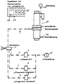
- the spray device contains a spray gun 1, which is connected to a compressed air source 5 via lines 2 to 4.
- a compressed air source 5 via lines 2 to 4.
- an ON / OFF air valve 6 an air control valve 7, which adjusts the compressed air supply to the horn air nozzles, not shown, and an air control valve 8, which is provided for the compressed air supply to the ring nozzle, also not shown.
- the spray gun 1 is also connected via a line 9 to a hydraulic volume metering device 10, the oil inlet of which is designated 11 and the material inlet 12.
- a control unit 13 for the volume dispenser 10 and the air valves 6 to 8 contains a monitor which displays the set / actual parameters, and an operating keyboard 15 with which the parameters of the medium and compressed air delivery can be set or changed.
- the hydraulic volume metering device 10 guides the medium at high pressure, i.e. with about 70 to 300 bar, and the air control valve 6 switches to OFF and thus interrupts the compressed air supply to the spray gun 1. If, on the other hand, the medium jet is to be narrowed, the volume metering device 10 reduces the pressure of the medium to approximately 10 to 70 bar, which Air control valve 6 is turned ON and the air control valves 7 and 8 adjust the compressed air supply to the ring air nozzle and the horn air nozzles according to the parameters entered in the control unit 13, whereby the desired medium jet geometry is generated.
Landscapes
- Nozzles (AREA)
- Application Of Or Painting With Fluid Materials (AREA)
Claims (6)
- Dispositif de pulvérisation destiné à l'application d'un produit liquide, tel que de la peinture etc., au moyen d'un pistolet de projection, qui est relié à une source de produit et qui présente une buse de sortie pour le produit sous pression,
caractérisé en ce que l'orifice de sortie de la buse de sortie du produit est entourée par une buse annulaire et/ou par plusieurs buses de corne, situées les unes en face des autres, dirigées obliquement sur le jet de produit sortant, et reliées à une source d'air comprimé (5),
en ce qu'on prévoit, dans les conduites (2, 3, 4) reliant la source d'air comprimé (5) au pistolet de projection (1), une soupape de commande d'air (6) à deux positions, une soupape de régulation d'air (7) pour la buse annulaire et/ou une soupape de régulation d'air (8) pour les buses de corne , et
en ce qu'une unité de réglage (13) extérieure est prévue pour les soupapes (6, 7, 8) et pour la pression du produit. - Dispositif de pulvérisation selon la revendication 1,
caractérisé en ce que l'orifice de sortie de la buse de sortie du produit est de forme conique. - Dispositif de pulvérisation selon la revendication 1 ou 2,
caractérisé en ce que le produit est amené à partir d'un doseur volumétrique (10) hydraulique. - Dispositif de pulvérisation selon l'une des revendications 1 à 3,
caractérisé par un dispositif de commande (6, 7, 8) pour la pression d'air. - Procédé d'application d'un produit liquide, tel que de la peinture, etc., au moyen d'un dispositif de pulvérisation selon les revendications précédentes,
caractérisé en ce que le produit présente une pression comprise entre environ 70 et 300 bars, lorsqu'il n'y a pas d'air comprimé sortant des buses, et en ce que la pression du produit est abaissée à une valeur comprise entre environ 10 et 70 bars, lorsque de l'air annulaire et/ou des jets des cornes sont amenés, pour rétrécir le jet de produit. - Procédé selon la revendication 5,
caractérisé en ce que, au choix, de l'air comprimé sort de la buse annulaire et/ou des buses de corne.
Applications Claiming Priority (2)
| Application Number | Priority Date | Filing Date | Title |
|---|---|---|---|
| DE4208500 | 1992-03-17 | ||
| DE4208500A DE4208500C2 (de) | 1992-03-17 | 1992-03-17 | Spritzvorrichtung zum Aufbringen eines flüssigen Mediums wie Farbe |
Publications (2)
| Publication Number | Publication Date |
|---|---|
| EP0561196A1 EP0561196A1 (fr) | 1993-09-22 |
| EP0561196B1 true EP0561196B1 (fr) | 1997-04-23 |
Family
ID=6454268
Family Applications (1)
| Application Number | Title | Priority Date | Filing Date |
|---|---|---|---|
| EP93103164A Expired - Lifetime EP0561196B1 (fr) | 1992-03-17 | 1993-02-27 | Dispositif de pulvérisation pour l'application d'un produit liquide comme de la peinture |
Country Status (3)
| Country | Link |
|---|---|
| EP (1) | EP0561196B1 (fr) |
| AT (1) | ATE152009T1 (fr) |
| DE (2) | DE4208500C2 (fr) |
Families Citing this family (14)
| Publication number | Priority date | Publication date | Assignee | Title |
|---|---|---|---|---|
| DE4335827C2 (de) * | 1993-10-20 | 2001-06-07 | Siemens Ag | Verfahren und Löschanlage zum Löschen eines Brandes |
| DE19610589A1 (de) * | 1996-03-18 | 1997-09-25 | Duerr Gmbh & Co | Verfahren und System zur Farbversorgung einer Beschichtungsanlage |
| DE19611533B4 (de) * | 1996-03-23 | 2005-11-03 | Itw Gema Ag | Vorrichtung zur Pulverbeschichtung |
| DE19615379C2 (de) * | 1996-04-18 | 2002-10-10 | Fraunhofer Ges Forschung | Pneumatische Handspritzpistole mit automatischer Spritzstrahlverstellung |
| DE19627353C1 (de) * | 1996-06-27 | 1997-10-23 | Feuerschutz G Knopf Gmbh | Verfahren zur dynamischen Löschmittelanwendung und Vorrichtung zur Durchführung des Verfahrens |
| DE20017630U1 (de) * | 1999-12-20 | 2001-03-22 | Tevkür, Talip, 13585 Berlin | Farbspritzpistole |
| DE102006017323B4 (de) * | 2005-04-12 | 2011-01-27 | B + M Surface Systems Gmbh | Sprühbeschichtungseinrichtung |
| US11826771B2 (en) | 2018-08-01 | 2023-11-28 | Sata Gmbh & Co. Kg | Set of nozzles for a spray gun, spray gun system, method for embodying a nozzle module, method for selecting a nozzle module from a set of nozzles for a paint job, selection system and computer program product |
| DE102018118737A1 (de) | 2018-08-01 | 2020-02-06 | Sata Gmbh & Co. Kg | Düse für eine Spritzpistole, Düsensatz für eine Spritzpistole, Spritzpistolen und Verfahren zur Herstellung einer Düse für eine Spritzpistole |
| DE102018118738A1 (de) | 2018-08-01 | 2020-02-06 | Sata Gmbh & Co. Kg | Grundkörper für eine Spritzpistole, Spritzpistolen, Spritzpistolen-Set, Verfahren zur Herstellung eines Grundkörpers für eine Spritzpistole und Verfahren zum Umrüsten einer Spritzpistole |
| DE102018122004A1 (de) | 2018-09-10 | 2020-03-12 | Sata Gmbh & Co. Kg | Lackierpistole, Materialauftragssystem und Verfahren zu dessen Betrieb |
| DE102020106171A1 (de) * | 2020-03-06 | 2021-09-09 | Sata Gmbh & Co. Kg | Spritzpistole, insbesondere Farbspritzpistole |
| DE102020106172A1 (de) | 2020-03-06 | 2021-09-09 | Sata Gmbh & Co. Kg | Spritzpistole, insbesondere druckluftzerstäubende Farbspritzpistole, insbesondere handgeführte druckluftzerstäubende Farbspritzpistole |
| DE102020123769A1 (de) | 2020-09-11 | 2022-03-17 | Sata Gmbh & Co. Kg | Dichtelement zum Abdichten eines Übergangs zwischen einem Grundkörper einer Spritzpistole und einem Anbauteil einer Spritzpistole, Anbauteil, insbesondere Farbdüsenanordnung, für eine Spritzpistole und Spritzpistole, insbesondere Farbspritzpistole |
Family Cites Families (8)
| Publication number | Priority date | Publication date | Assignee | Title |
|---|---|---|---|---|
| DE2542030A1 (de) * | 1975-09-20 | 1977-03-24 | Wilhelm Fleissner | Pumpenaggregat |
| DE3409961A1 (de) * | 1984-03-17 | 1985-09-19 | Basf Farben + Fasern Ag, 2000 Hamburg | Vorrichtung zum aufbringen von fluidproben, wie farben, lacke od. dgl. |
| GB2167320B (en) * | 1984-09-19 | 1988-03-16 | Bl Tech Ltd | A spray control system |
| DE3507814A1 (de) * | 1985-03-06 | 1985-11-21 | Josef 7963 Eichstegen Nusser | Dosiereinrichtung, insbesondere fuer mehrkomponentenspritzpistole |
| DE3720991A1 (de) * | 1987-06-25 | 1989-03-30 | Fere Dosier Und Klebsysteme Gm | Spritzvorrichtung mit materialflusskontrolle |
| IT1221554B (it) * | 1987-11-12 | 1990-07-12 | T M Di Tiziana Mazza | Sistema per applicare a spruzzo films di adesivo ed apparecchiatura per attuare detto sistema |
| DE3822835A1 (de) * | 1988-07-06 | 1990-03-08 | Josef Schucker | Verfahren und anordnung zum lackieren von werkstueckoberflaechen |
| ATE93417T1 (de) * | 1989-07-19 | 1993-09-15 | Sata Farbspritztechnik | Duesenkopf. |
-
1992
- 1992-03-17 DE DE4208500A patent/DE4208500C2/de not_active Expired - Fee Related
-
1993
- 1993-02-27 EP EP93103164A patent/EP0561196B1/fr not_active Expired - Lifetime
- 1993-02-27 DE DE59306227T patent/DE59306227D1/de not_active Expired - Fee Related
- 1993-02-27 AT AT93103164T patent/ATE152009T1/de not_active IP Right Cessation
Also Published As
| Publication number | Publication date |
|---|---|
| DE4208500A1 (de) | 1993-09-23 |
| DE59306227D1 (de) | 1997-05-28 |
| ATE152009T1 (de) | 1997-05-15 |
| EP0561196A1 (fr) | 1993-09-22 |
| DE4208500C2 (de) | 1994-05-11 |
Similar Documents
| Publication | Publication Date | Title |
|---|---|---|
| EP0561196B1 (fr) | Dispositif de pulvérisation pour l'application d'un produit liquide comme de la peinture | |
| EP0192097B1 (fr) | Procédé de revêtement des objets, par pulvérisation et pistolet pour exécuter ce procédé | |
| EP3626352B1 (fr) | Corps de base pour un pistolet de pulvérisation, pistolet de pulvérisation, ensemble pistolet de pulvérisation et procédé de rééquipement d'un pistolet de pulvérisation | |
| EP0576498B2 (fr) | Procede et dispositif d'application d'une matiere pateuse | |
| DE2422597B2 (de) | Spritzvorrichtung zum hydrostatischen Zerstäuben von Farbe und anderen flüssigen Stoffen | |
| DE1948401A1 (de) | Spritzvorrichtung fuer viskose Fluessigkeiten | |
| EP0442019A1 (fr) | Procédé de mise en oeuvre d'un pistolet électrostatique et pneumatique pour la pulvérisation de peintures | |
| EP3610950A1 (fr) | Buse pour pistolet pulvérisateur, ensemble de buse pour pistolet pulvérisateur, pistolets pulvérisateurs et procédé de fabrication d'une buse pour pistolet pulvérisateur | |
| EP3829778B1 (fr) | Jeu de buses pour un pistolet pulvérisateur, système de pistolet pulvérisateur, procédé de réalisation d'un module de buses, procédé de sélection d'un module de buses d'un jeu de buses pour un travail de peinture, système de sélection et produit-programme informatique | |
| EP2056970B2 (fr) | Dispositif de nettoyage de pulvérisateurs, en particulier de pistolets de projection de peinture, et procédé de nettoyage d'un pulvérisateur | |
| EP0763385A1 (fr) | Procédé de transport d'un matériaux pulvérulent au moyen d'un injecteur | |
| DE202010015304U1 (de) | Düse | |
| EP1054738B1 (fr) | Tete de generateur de brouillard | |
| DE19917219B4 (de) | Schmiervorrichtung | |
| EP1889666B1 (fr) | Dispositif destiné à recouvrir, en particulier pur laquer, des objets, en particulier de véhicules automobiles | |
| WO2013139811A1 (fr) | Procédé de pulvérisation sans air, dispositif de pulvérisation sans air, système de revêtement et capuchon de buse | |
| DE102024107327A1 (de) | Lufttrennring zum Zuführen von Zerstäuberluft und Formluft innerhalb einer Lackierpistole | |
| CH712915A2 (de) | Vorrichtung zum Versprühen von fliessfähigen Fluiden und Verwendung der Vorrichtung. | |
| WO2025132041A1 (fr) | Pistolet à peinture | |
| WO2002055214A1 (fr) | Dispositif pour enduire une piece allongee | |
| WO2025190527A1 (fr) | Buse de pulvérisation de peinture pour pistolet à peinture | |
| DE3441079C1 (de) | Abschirmeinrichtung für Detonationsanlagen zum Auftragen von Überzügen | |
| DE202015009893U1 (de) | Roboterwerkzeug und Roboter zur Abgabe eines Korrosionsschutzwachses | |
| DE2249291A1 (de) | Verfahren und vorrichtung zum luftlosen zerstaeuben fluessiger medien | |
| DE29621384U1 (de) | Spritzpistole zum Verteilen und Aufbringen von Massen mit einem hohen Anteil an Bitumen-Wasser-Emulsion |
Legal Events
| Date | Code | Title | Description |
|---|---|---|---|
| PUAI | Public reference made under article 153(3) epc to a published international application that has entered the european phase |
Free format text: ORIGINAL CODE: 0009012 |
|
| AK | Designated contracting states |
Kind code of ref document: A1 Designated state(s): AT BE DE ES FR GB IT NL PT SE |
|
| 17P | Request for examination filed |
Effective date: 19940316 |
|
| 17Q | First examination report despatched |
Effective date: 19950531 |
|
| GRAG | Despatch of communication of intention to grant |
Free format text: ORIGINAL CODE: EPIDOS AGRA |
|
| GRAH | Despatch of communication of intention to grant a patent |
Free format text: ORIGINAL CODE: EPIDOS IGRA |
|
| GRAH | Despatch of communication of intention to grant a patent |
Free format text: ORIGINAL CODE: EPIDOS IGRA |
|
| GRAA | (expected) grant |
Free format text: ORIGINAL CODE: 0009210 |
|
| AK | Designated contracting states |
Kind code of ref document: B1 Designated state(s): AT BE DE ES FR GB IT NL PT SE |
|
| PG25 | Lapsed in a contracting state [announced via postgrant information from national office to epo] |
Ref country code: NL Effective date: 19970423 Ref country code: IT Free format text: LAPSE BECAUSE OF FAILURE TO SUBMIT A TRANSLATION OF THE DESCRIPTION OR TO PAY THE FEE WITHIN THE PRESCRIBED TIME-LIMIT;WARNING: LAPSES OF ITALIAN PATENTS WITH EFFECTIVE DATE BEFORE 2007 MAY HAVE OCCURRED AT ANY TIME BEFORE 2007. THE CORRECT EFFECTIVE DATE MAY BE DIFFERENT FROM THE ONE RECORDED. Effective date: 19970423 Ref country code: FR Effective date: 19970423 Ref country code: ES Free format text: THE PATENT HAS BEEN ANNULLED BY A DECISION OF A NATIONAL AUTHORITY Effective date: 19970423 |
|
| REF | Corresponds to: |
Ref document number: 152009 Country of ref document: AT Date of ref document: 19970515 Kind code of ref document: T |
|
| GBT | Gb: translation of ep patent filed (gb section 77(6)(a)/1977) |
Effective date: 19970424 |
|
| REF | Corresponds to: |
Ref document number: 59306227 Country of ref document: DE Date of ref document: 19970528 |
|
| PG25 | Lapsed in a contracting state [announced via postgrant information from national office to epo] |
Ref country code: SE Effective date: 19970723 Ref country code: PT Effective date: 19970723 |
|
| EN | Fr: translation not filed | ||
| NLV1 | Nl: lapsed or annulled due to failure to fulfill the requirements of art. 29p and 29m of the patents act | ||
| PG25 | Lapsed in a contracting state [announced via postgrant information from national office to epo] |
Ref country code: AT Free format text: LAPSE BECAUSE OF NON-PAYMENT OF DUE FEES Effective date: 19980227 |
|
| PLBE | No opposition filed within time limit |
Free format text: ORIGINAL CODE: 0009261 |
|
| STAA | Information on the status of an ep patent application or granted ep patent |
Free format text: STATUS: NO OPPOSITION FILED WITHIN TIME LIMIT |
|
| PG25 | Lapsed in a contracting state [announced via postgrant information from national office to epo] |
Ref country code: BE Free format text: LAPSE BECAUSE OF NON-PAYMENT OF DUE FEES Effective date: 19980228 |
|
| 26N | No opposition filed | ||
| BERE | Be: lapsed |
Owner name: KLAUS KLEINMICHEL G.M.B.H. Effective date: 19980228 |
|
| REG | Reference to a national code |
Ref country code: GB Ref legal event code: IF02 |
|
| PGFP | Annual fee paid to national office [announced via postgrant information from national office to epo] |
Ref country code: GB Payment date: 20040225 Year of fee payment: 12 |
|
| PGFP | Annual fee paid to national office [announced via postgrant information from national office to epo] |
Ref country code: DE Payment date: 20040427 Year of fee payment: 12 |
|
| PG25 | Lapsed in a contracting state [announced via postgrant information from national office to epo] |
Ref country code: GB Free format text: LAPSE BECAUSE OF NON-PAYMENT OF DUE FEES Effective date: 20050227 |
|
| PG25 | Lapsed in a contracting state [announced via postgrant information from national office to epo] |
Ref country code: DE Free format text: LAPSE BECAUSE OF NON-PAYMENT OF DUE FEES Effective date: 20050901 |
|
| GBPC | Gb: european patent ceased through non-payment of renewal fee |
Effective date: 20050227 |