EP3829778B1 - Jeu de buses pour un pistolet pulvérisateur, système de pistolet pulvérisateur, procédé de réalisation d'un module de buses, procédé de sélection d'un module de buses d'un jeu de buses pour un travail de peinture, système de sélection et produit-programme informatique - Google Patents
Jeu de buses pour un pistolet pulvérisateur, système de pistolet pulvérisateur, procédé de réalisation d'un module de buses, procédé de sélection d'un module de buses d'un jeu de buses pour un travail de peinture, système de sélection et produit-programme informatique Download PDFInfo
- Publication number
- EP3829778B1 EP3829778B1 EP18758803.3A EP18758803A EP3829778B1 EP 3829778 B1 EP3829778 B1 EP 3829778B1 EP 18758803 A EP18758803 A EP 18758803A EP 3829778 B1 EP3829778 B1 EP 3829778B1
- Authority
- EP
- European Patent Office
- Prior art keywords
- nozzle
- spray
- nozzle module
- modules
- spray jet
- Prior art date
- Legal status (The legal status is an assumption and is not a legal conclusion. Google has not performed a legal analysis and makes no representation as to the accuracy of the status listed.)
- Active
Links
Images


Classifications
-
- B—PERFORMING OPERATIONS; TRANSPORTING
- B05—SPRAYING OR ATOMISING IN GENERAL; APPLYING FLUENT MATERIALS TO SURFACES, IN GENERAL
- B05B—SPRAYING APPARATUS; ATOMISING APPARATUS; NOZZLES
- B05B7/00—Spraying apparatus for discharge of liquids or other fluent materials from two or more sources, e.g. of liquid and air, of powder and gas
- B05B7/02—Spray pistols; Apparatus for discharge
- B05B7/08—Spray pistols; Apparatus for discharge with separate outlet orifices, e.g. to form parallel jets, i.e. the axis of the jets being parallel, to form intersecting jets, i.e. the axis of the jets converging but not necessarily intersecting at a point
- B05B7/0807—Spray pistols; Apparatus for discharge with separate outlet orifices, e.g. to form parallel jets, i.e. the axis of the jets being parallel, to form intersecting jets, i.e. the axis of the jets converging but not necessarily intersecting at a point to form intersecting jets
- B05B7/0815—Spray pistols; Apparatus for discharge with separate outlet orifices, e.g. to form parallel jets, i.e. the axis of the jets being parallel, to form intersecting jets, i.e. the axis of the jets converging but not necessarily intersecting at a point to form intersecting jets with at least one gas jet intersecting a jet constituted by a liquid or a mixture containing a liquid for controlling the shape of the latter
-
- B—PERFORMING OPERATIONS; TRANSPORTING
- B05—SPRAYING OR ATOMISING IN GENERAL; APPLYING FLUENT MATERIALS TO SURFACES, IN GENERAL
- B05B—SPRAYING APPARATUS; ATOMISING APPARATUS; NOZZLES
- B05B1/00—Nozzles, spray heads or other outlets, with or without auxiliary devices such as valves, heating means
- B05B1/02—Nozzles, spray heads or other outlets, with or without auxiliary devices such as valves, heating means designed to produce a jet, spray, or other discharge of particular shape or nature, e.g. in single drops, or having an outlet of particular shape
- B05B1/04—Nozzles, spray heads or other outlets, with or without auxiliary devices such as valves, heating means designed to produce a jet, spray, or other discharge of particular shape or nature, e.g. in single drops, or having an outlet of particular shape in flat form, e.g. fan-like, sheet-like
- B05B1/044—Slits, e.g. narrow openings defined by two straight and parallel lips; Elongated outlets for producing very wide discharges, e.g. fluid curtains
-
- B—PERFORMING OPERATIONS; TRANSPORTING
- B05—SPRAYING OR ATOMISING IN GENERAL; APPLYING FLUENT MATERIALS TO SURFACES, IN GENERAL
- B05B—SPRAYING APPARATUS; ATOMISING APPARATUS; NOZZLES
- B05B1/00—Nozzles, spray heads or other outlets, with or without auxiliary devices such as valves, heating means
- B05B1/14—Nozzles, spray heads or other outlets, with or without auxiliary devices such as valves, heating means with multiple outlet openings; with strainers in or outside the outlet opening
Definitions
- the invention relates to a method for designing a nozzle module according to the preamble of claim 1.
- the air cap has a central opening whose diameter is larger than the outer diameter of the material nozzle protrusion or the outer diameter of the front end of a conical material nozzle.
- the central opening of the air cap and the suppository, or the front end of the material nozzle together form an annular gap.
- the so-called atomizing air emerges from this annular gap. In the nozzle arrangement described above, this creates a vacuum at the front of the material nozzle, sucking the material to be sprayed out of the material nozzle.
- the atomizing air strikes the paint jet, tearing the paint jet into threads and bands. Due to their hydrodynamic instability, the interaction between the fast-flowing compressed air and the ambient air, and aerodynamic disturbances, these threads and bands break up into droplets, which are blown away from the nozzle by the atomizing air.
- Such a spray gun is used, for example, in the US 5,456,414 A revealed.
- the air cap frequently also has two horns, which are diametrically opposed to each other and project beyond the aforementioned annular gap and the material outlet opening in the outflow direction.
- Two supply bores i.e., horn air supply channels, run from the rear of the air cap to horn air outlet openings in the horns.
- each horn has at least one horn air outlet opening, but preferably each horn has at least two horn air outlet openings from which the horn air exits.
- Horn air outlets are generally oriented so that they point toward the nozzle's longitudinal axis in the outlet direction after the annular gap, so that the so-called horn air exiting the horn air outlets can influence the air already exiting the annular gap, or the paint jet, or the paint mist that has already at least partially formed.
- the horn air also serves to further atomize the spray jet.
- the aforementioned material nozzle typically has a hollow main section and a substantially hollow-cylindrical front section with a material outlet opening, through which the material to be sprayed flows.
- the spray gun can be equipped with material nozzles with differently sized material outlet openings, i.e. material outlet openings with different inner diameters. If the material to be sprayed, e.g. paint, is a higher-viscosity material, such as filler, a material nozzle with a material outlet opening with a larger inner diameter should generally be selected than for a lower-viscosity material such as clear coat.
- the inner diameter of a material outlet opening of a material nozzle is typically between a few tenths of a millimeter and several millimeters.
- a fluid nozzle with a fluid outlet opening of a specific inner diameter is often referred to as a fluid nozzle with a specific "nozzle size", although the value of this nominal nozzle size does not have to exactly match the value of the inner diameter of the fluid outlet opening.
- the material nozzle or the spray gun equipped with the material nozzle can have a certain material throughput.
- the material throughput describes the amount of material that emerges from the material nozzle of the spray gun in a certain time, with a defined inlet flow pressure and fully actuated trigger. The value is given in grams per minute (g/min).
- the material throughput increases with the nozzle size, whereby the material throughput is influenced not only by the inner diameter of the material outlet opening, but also by the length of the hollow cylindrical front section, the arrangement of the various surfaces inside the material nozzle, in particular the angles at which the surfaces are arranged to one another, and by other designs of the material nozzle.
- the size of the spray jet produced by the spray gun changes with increasing material throughput, in particular the height and/or width of the spray jet or the spray jet cross-section.
- the spray jet cross-section can be illustrated by means of a so-called spray pattern.
- a spray pattern is usually created by applying paint or varnish to a sheet of paper or sheet of paper using the spray gun, which is held at a certain distance, for example 15 cm to 20 cm, in front of a substrate, e.g. paper, a paper with a scale intended for creating a spray pattern, or a sheet of metal, without moving the spray gun.
- the spraying time is approximately 1 to 2 seconds.
- the shape of the spray pattern produced in this way and the size of the droplets on the substrate provide information about the quality of the spray gun, in particular the quality of the nozzles.
- the layer thickness of the spray pattern can be determined using methods known in the state of the art, e.g. using layer thickness gauges before or after the spray pattern has dried, or the paint droplets as well as their size and position can be recorded while they are flying onto the substrate, e.g. using laser diffraction methods.
- a spray pattern as described above does not have a uniform layer thickness across its length and width.
- the central core of the spray pattern has a thick layer thickness, while outside the core the layer thickness created is less.
- the layer thickness transition between the core and the outer region is fluid. If the layer thickness is plotted over the length of the spray pattern, there is initially a gentle increase from left to right, which marks the outer edge of the outer region. Close to the core the layer thickness increases relatively steeply and ideally remains essentially constant over the length of the core, i.e. a plateau is formed. At the edge of the core the layer thickness drops off relatively steeply, followed by a gentler decrease towards the end of the outer region.
- the transition must not be too steep, as otherwise there is a risk of Overcoating, e.g., by accidentally applying twice the layer thickness, can lead to so-called paint runs. Furthermore, tests have shown that it is advantageous if the aforementioned plateau is as wide as possible, i.e., the core area of the spray pattern with maximum layer thickness is as long as possible.
- the spray pattern represents the spray jet cross-section.
- spray jet cross-sectional height, spray jet cross-sectional width, or cross-sectional shape of the spray jet this refers to the height, width, or shape of the spray pattern, respectively, in particular the height, width, or shape of the core area of the spray pattern.
- the size of the spray jet generated by the spray gun changes with increasing material throughput, particularly the height and/or width of the spray jet, the spray jet cross-section, or the spray jet core cross-section.
- increasing material throughput not only does the spray jet become "wetter” as desired, i.e., more material is applied per area, but the spray jet cross-section also becomes higher and/or wider.
- the material throughput does not increase uniformly with increasing nozzle size, especially the nominal nozzle size.
- a so-called 1.2 mm nozzle may have a material throughput 10 g/min higher than a 1.1 mm nozzle, but a material throughput 20 g/min lower than a 1.3 mm nozzle. Therefore, with each nozzle change, the spray gun user must adapt their working methods to the new nozzle. For example, if the user wants to spray a material with a certain viscosity and then a material with a different viscosity and therefore switches from one nozzle size to another, they must, for example, adjust the distance of the spray gun to the surface to be coated or their painting speed, i.e., the speed at which they move the spray gun over the surface to be coated, to the new nozzle. This can complicate the work of the spray gun user. Furthermore, according to the state of the art, the user of spray guns does not have the option of selecting a spray shape that is advantageous for them and their working method, i.e., a spray jet with a spray jet cross-section that is advantageous for them.
- the object of the present invention is therefore to provide an efficient method for designing a nozzle module.
- a nozzle set for a spray gun in particular a compressed air atomizing paint spray gun, has at least one nozzle module group with at least two, preferably at least four, different nozzle modules for optional attachment in or on one and the same Main body module of a spray gun, wherein the nozzle modules are designed such that they have a different material throughput under the same spraying conditions, and wherein the spray jets that can be generated by means of the nozzle modules have essentially the same spray jet cross-sectional height and the same spray jet cross-sectional width, in particular the spray jet cross-sections of the different nozzle modules are congruent.
- the nozzle modules within the nozzle module group each have a different material throughput; in particular, they are nozzles with different nozzle sizes, especially nominal nozzle sizes.
- the nozzle module group can, for example, comprise a 1.1 nozzle module, a 1.2 nozzle module, a 1.3 nozzle module, a 1.4 nozzle module, and a 1.5 nozzle module, which have a material throughput that increases with the nominal nozzle size.
- the nominal nozzle size can essentially correspond to the actual nozzle size, i.e., the actual inner diameter of the material outlet opening of the paint nozzle of the nozzle module in millimeters.
- the inner diameter of the 1.5 nozzle module can be 1.5 mm.
- the 1.3 nozzle module can, for example, have an inner diameter of the material outlet opening of the paint nozzle of 1.4 mm, whereby the material throughput can be reduced compared to the 1.4 nozzle module, for example, through different geometries and/or dimensions, in particular angles and lengths, in particular the length of a substantially hollow cylindrical front section of the paint nozzle.
- the material outlet opening of the paint nozzle of the 1.4 nozzle module can have a larger inner diameter than 1.4 mm.
- the at least two, preferably at least four, different nozzle modules of the nozzle module group of the nozzle set according to the invention can be arranged optionally in or on one and the same base body module of a spray gun.
- a first nozzle module arranged on the base body module for example a nozzle module with a first material throughput, for example a 1.2 nozzle module with a material throughput of 150 g/min, can be removed from the base body module, in particular unscrewed, preferably via a quick-release screw closure, and another nozzle module from the nozzle module group of the nozzle set according to the invention with a second material throughput, for example a 1.5 nozzle module with a material throughput of 195 g/min, can be arranged on the same base body module, preferably via the same quick-release screw closure.
- the nozzle modules of the nozzle module group of the nozzle set according to the invention have different material throughputs, and the spray jets generated by the nozzle modules have essentially the same spray jet cross-sectional height and spray jet cross-sectional width.
- the spraying conditions that should be identical can include, for example, the inlet flow pressure, the air pressure at the inlet of the spray gun, the distance and angle of the spray gun to the object to be coated, the material to be sprayed, the degree of actuation of the trigger guard, the setting of a round-to-wide jet regulator, but also climatic conditions such as temperature, air humidity, and ambient pressure.
- the spray pattern is intended to represent the spray jet cross-section.
- the spray jet cross-sectional height and the spray jet cross-sectional width are essentially the same means that the height and width of the spray pattern, in particular the core of the spray pattern, i.e., the area of the spray pattern with the highest layer thickness, are essentially the same.
- the spray jet cross-sections of the various nozzle modules are congruent, i.e., the spray patterns are essentially identical in shape and size. Due to the different material throughputs of the nozzle modules, the layer thickness of the spray patterns varies.
- a nozzle module can, in particular, comprise a material nozzle and an air cap. It can also comprise an air nozzle ring, via which the nozzle module can be screwed to the base module, and a paint needle for closing and releasing the material outlet opening of the material nozzle.
- An advantage of the nozzle set according to the invention is that the user of the spray gun, for example the vehicle painter, does not have to accept any change in the spray jet cross-sectional height and width when changing the nozzle size, i.e., when replacing the nozzle module arranged on the base module of the spray gun with a first material throughput with a nozzle module with a second material throughput.
- the newly arranged nozzle produces a spray jet with the same cross-sectional shape and dimensions as with the removed nozzle. The painter therefore does not have to change his working method, in particular the distance of the spray gun from the object to be coated, after changing the nozzle.
- the spray gun system according to the invention is characterized in that it has at least one nozzle set described in more detail above and below and a base body module, wherein the nozzle modules of the nozzle set can be arranged interchangeably on the base body module.
- Each of the various nozzle modules from the various nozzle module groups can be arranged interchangeably on one and the same base body module.
- the various nozzle modules have the same connection type, so that they can be arranged directly on the base body module, for example via a thread, in particular a trapezoidal thread, which can be designed as a quick-action screw closure or connection, or via a bayonet connection, a plug connection, or via another connection known in the art.
- a first nozzle module to have a different connection type than a second nozzle module, and for one of the nozzle modules to be arranged on the base body module via an adapter.
- the method according to the invention for designing a nozzle module comprises at least one step of defining at least one spray jet cross-sectional height and/or a spray jet cross-sectional width and/or a spray jet cross-sectional shape of a spray jet to be generated by the nozzle module, and at least one further step of constructing the nozzle module which generates a spray jet with the defined spray jet cross-sectional height and/or spray jet cross-sectional width and/or spray jet cross-sectional shape, wherein the method comprises constructing an air cap, in particular adapting an outer horn air outflow angle and/or an inner horn air outflow angle and/or a control bore distance to a material throughput and/or to an internal nozzle pressure of the nozzle module, wherein the outer horn air outflow angle is the angle at which horn air from an outer horn air outlet opening the air cap relative to a vertical axis, wherein the vertical axis is perpendicular
- the spray jet to be generated by the nozzle module should have a spray jet cross-sectional height of approximately 27 cm and/or a spray jet cross-sectional width of approximately 4 cm and/or an oval, particularly elliptical, spray jet cross-sectional shape.
- This also concerns the height, width, and shape of the spray pattern, particularly the core of the spray pattern.
- the nozzle module which generates a spray jet with the specified spray jet cross-sectional height, spray jet cross-sectional width, and/or spray jet cross-sectional shape, is constructed.
- an air cap is constructed for the nozzle module.
- Such an air cap can in particular have two horns which are diametrically opposed to one another and project forwards, i.e. in the spray direction, beyond a central opening in the air cap.
- Two supply bores i.e. horn air supply channels, run from the rear of the air cap to horn air outlet openings in the horns.
- each horn has at least two horn air outlet openings from which the horn air exits.
- the horn air outlet openings are generally oriented such that the horn air exiting the horn air outlet openings can influence the air that has already escaped from the above-mentioned annular gap or the paint jet or the paint mist that has already at least partially formed.
- Such an air cap can furthermore have control openings in the area next to the central opening.
- These control openings which will be referred to below as control bores even though they do not have to be designed as bores but are preferably so, extend into the interior of the air cap and are supplied with air from there when the spray gun is in operation.
- the air escaping from the control bores the so-called control air, meets the horn air escaping from the horn air outlet openings and deflects it, fanning out the horn air jet, i.e. it widens it and weakens the horn air jet.
- the control air also acts on the round jet, causing a slight pre-deformation and, here too, additional atomization.
- the control air contributes to further atomization of the paint jet and reduces contamination of the air cap by spray mist, as it carries this away from the air cap.
- the air cap can have three control bores arranged on two opposite sides of the central opening, which are arranged in the shape of a triangle, with one tip of the triangle being aligned towards the inner or outer horn air outlet openings, i.e. the bore forming the tip of the triangle is preferably in line with the inner horn air outlet opening, the outer horn air outlet openings and the center point of the central opening in the air cap.
- the control bores can have the same diameter, advantageously between 0.45 mm and 0.65 mm.
- the air cap can also have only two control bores arranged on two opposite sides of the central opening, which are preferably in line and in line with the inner horn air outlet opening, the outer horn air outlet openings and the center point of the central opening in the air cap.
- the method according to the invention comprises in particular the adaptation of an outer horn air outflow angle and/or an inner horn air outflow angle and/or a control bore distance to a material throughput and/or to a nozzle internal pressure of the Nozzle module, wherein the outer horn air outflow angle is the angle at which horn air flows out of an outer horn air outlet opening of the air cap relative to a vertical axis, the vertical axis being perpendicular to a central axis of the air cap, wherein the inner horn air outflow angle is the angle at which horn air flows out of an inner horn air outlet opening of the air cap relative to the vertical axis, and wherein the control bore distance is the distance between at least one control bore in the air cap and a central opening in the air cap.
- the horn air outlet angle is the angle at which the majority of the horn air, or the center of the horn air jet, flows out relative to the described vertical axis.
- the horn air outlet angle can be the angle of the central axis of the horn air outlet channel, in particular of the horn air outlet bore, the end of which forms the horn air outlet opening, relative to the vertical axis.
- the central axis of the air cap, to which the vertical axis is perpendicular, runs in particular through the center of the central opening in the air cap.
- control bore distance is understood here as the distance between the above-mentioned central axis of the air cap and an axis parallel to this central axis through the center of the corresponding control bore. Otherwise, the control bore distance is understood here as the distance between the above-mentioned central axis and an axis parallel to this central axis through a projection of the center of the corresponding control bore onto the cross-sectional plane.
- the cross-sectional plane preferably runs in particular along the central axis of the air cap and through the centers of the horn air outlet openings.
- an outer horn air outlet angle and/or an inner horn air outlet angle and/or a control bore distance is adapted to a material throughput and/or to a nozzle internal pressure of the nozzle module within the scope of the method according to the invention means that the outer horn air outlet angle, inner horn air outlet angle and/or control bore distance must be dimensioned as a function of a material throughput and/or a nozzle internal pressure.
- a nozzle module with a first material throughput and/or at a first nozzle internal pressure generates a spray jet with the specified spray jet cross-sectional height and/or spray jet cross-sectional width and/or spray jet cross-sectional shape because it has a suitable outer horn air outlet angle, inner horn air outflow angle and/or control bore distance
- the outer horn air outflow angle, the inner horn air outflow angle and/or the control bore distance must be changed in order to achieve a spray jet with the specified spray jet cross-sectional height and/or spray jet cross-sectional width and/or spray jet cross-sectional shape.
- a changed material throughput occurs in particular when a material nozzle with a different nozzle size is used.
- a changed nozzle internal pressure occurs in particular when a low-pressure nozzle module is used first and then a high-pressure nozzle module, or when a low-pressure base body module is used first and then a high-pressure base body module is used.
- changes to the air cap can also have an influence on the nozzle internal pressure.
- an outer horn air outlet angle, an inner horn air outlet angle, and/or a control bore spacing of the air cap are precisely matched to the material throughput and/or the internal nozzle pressure of the nozzle module so that the nozzle module generates a spray jet with the specified, i.e., desired, spray jet cross-sectional height and/or spray jet cross-sectional width and/or spray jet cross-sectional shape.
- the outer horn air outlet angle of the first horn is equal to the outer horn air outlet angle of the second horn
- the inner horn air outlet angle of the first horn is equal to the inner horn air outlet angle of the second horn
- the control bore spacing(s) of the control bores on one side of the central opening are equal to the control bore spacing(s) of the control bores on the opposite side of the central opening.
- the method according to the invention for selecting a nozzle module from a nozzle set described in more detail above and below for a painting task is characterized in that the method comprises at least the selection and/or specification of one or more of the following properties of the painting task: previously used nozzle module of a nozzle set according to one of claims 1 to 8, previously used nozzle module of another nozzle set, spray pressure method, spray gun model, spray gun manufacturer, type of medium to be sprayed, viscosity of the medium to be sprayed, recommendation of the manufacturer of the medium to be sprayed, spray jet shape, layer thickness, climatic conditions, painting speed, controllability, nozzle size, and that, based on the selection or specification, a suggestion for a nozzle module of the nozzle set is generated.
- the process can comprise various stages with different selection and/or specification options.
- the selection or specification can be provided as to whether the suggestion for a nozzle module of the nozzle set should be generated based on a previously used nozzle module of a nozzle set described in more detail above and below, a previously used nozzle module of another nozzle set, the type of medium to be sprayed and/or based on the layer thickness to be achieved, in particular the layer thickness to be achieved per spray pass.
- various further properties of the painting task can be selected and/or specified. For example, water-based paint, solvent-based paint, clear coat or 2-component paint can be selected as the type of medium to be sprayed.
- spray pressure processes for example, low-pressure processes, in particular HVLP, or high-pressure processes, in particular compliant, can be selected or specified.
- a single nozzle size for example 1.1, 1.2 or 1.3, or a nozzle size range, for example 1.0 to 1.2, 1.3 to 1.5 etc. can be selected or specified as the nozzle size used.
- the viscosity of the medium to be sprayed can be specified or selected as a value or as a viscosity range, such as low viscosity, normal or high viscosity, preferably with an indication of a value range, in particular in seconds, that the material needs to completely run out of a standardized container, in particular from a DIN4 cup.
- the desired spray jet shape can be specified or selected, for example, as a spray jet with a cross-section with an essentially constant width at least in some regions (I-jet) or a spray jet with a cross-section with an essentially oval, in particular essentially elliptical, shape (O-jet).
- the climatic conditions can in particular be the temperature and/or the relative humidity in the paint booth in which the nozzle module is to be used.
- the indication of the painting speed and the controllability can preferably be designed as mutually influencing sliders, which indicate whether the user attaches more importance to a high painting speed or good controllability of the application. The sum of the value for the importance of the painting speed and the value for the importance of controllability can in particular always be 100%.
- the division can thus be, for example, 0% painting speed and 100% controllability if the user only attaches importance to good controllability, it can be 100% painting speed and 0% controllability if the user only attaches importance to a high painting speed, or it can be 25% painting speed and 75% controllability, 50% painting speed, and 50% controllability, 75% painting speed, and 25% controllability.
- the specification can be made, in particular, in 1% increments.
- the suggestion for a nozzle module of the nozzle set which is generated based on the selection or specification of one or more properties of the painting task, is preferably output, in particular displayed.
- the method according to the invention preferably comprises sending the suggestion for a nozzle module of the nozzle set by email or by means of another data transmission system.
- the selection system according to the invention in particular a "slider system" for carrying out the above-mentioned method, is characterized in that it comprises selection or input means for the properties of the painting task as well as means for generating and displaying a proposal for a nozzle module of the nozzle set.
- the selection system can, for example, consist of several mutually movable elements, e.g., made of paper or cardboard, which form the selection or input means for the properties of the painting task. Once the properties of the painting task have been fully selected or entered, the selection system according to the invention then displays the proposal for a nozzle module of the nozzle set.
- the computer program product according to the invention is characterized in that it comprises instructions which, when the program is executed by a data processing device, cause the device to generate a method or the steps of the selection system described in more detail above and below.
- the computer program product according to the invention can have a menu navigation which, in accordance with the selection system described in more detail above and below, or the method described in more detail above and below for selecting a nozzle module from a nozzle set for a painting task, comprises various stages with different selection and/or specification options.
- a first stage can provide for the selection or specification of whether the suggestion for a nozzle module of the nozzle set should be generated based on a previously used nozzle module of a nozzle set described in more detail above and below, a previously used nozzle module of another nozzle set, the type of medium to be sprayed and/or based on the layer thickness to be achieved, in particular the layer thickness to be achieved per spray pass.
- various additional menu items may appear through which the properties of the painting task can be selected and/or specified.
- the data processing device can, in particular, be a smartphone, or a desktop, notebook, or tablet computer.
- the computer program product according to the invention can be configured such that the suggestion for a nozzle module of the nozzle set, which is generated based on the selection or specification of one or more properties of the painting task, is output, in particular displayed.
- the computer program product according to the invention is configured such that the suggestion for a nozzle module of the nozzle set can be sent by email or by means of another data transmission system.
- the nozzle set according to the invention has at least one further (second) nozzle module group, which comprises at least two, preferably at least four, different nozzle modules for optional attachment in or on one and the same base body module, wherein the nozzle modules of the further nozzle module group are also designed in such a way that they have a different material throughput under the same spraying conditions and the spray jets that can be generated by means of the nozzle modules have essentially the same spray jet cross-sectional height and the same spray jet cross-sectional width, in particular the spray jet cross-sections of the different nozzle modules are congruent, wherein the spray jets that can be generated by means of the nozzle modules of the two nozzle module groups each have different cross-sectional shapes, in particular in such a way that the spray jets that can be generated by means of the nozzle modules of one nozzle module group have a cross-section with at least some regions a substantially constant width (I-nozzle modules) and the spray jets that can be generated by means of the nozzle modules the spray jets that
- the further, in particular second, nozzle module group also has at least two, preferably at least four, different nozzle modules for optional attachment in or on one and the same base body module, wherein the nozzle modules of the further nozzle module group are also designed in such a way that they have a different material throughput under the same spraying conditions and the spray jets that can be generated by means of the nozzle modules have essentially the same spray jet cross-sectional height and the same spray jet cross-sectional width, in particular the spray jet cross-sections of the various nozzle modules are congruent.
- the spray jets that can be generated by means of the nozzle modules of the two nozzle module groups i.e., the first nozzle module group and the further, in particular second, nozzle module group
- each have different cross-sectional shapes, in particular such that the spray jets that can be generated by means of the nozzle modules of one nozzle module group have a cross-section with a substantially constant width, at least in some regions (I-nozzle modules), and the spray jets that can be generated by means of the nozzle modules of the other nozzle module group have a cross-section with a substantially oval, in particular substantially elliptical, shape (O-nozzle modules).
- the nozzle modules with spray jets with a cross-section with a substantially constant width, at least in some regions, are referred to below as I-nozzle modules, and a spray jet generated by means of an I-nozzle module is referred to as an I-jet.
- the nozzle modules with spray jets that are essentially oval, and in particular essentially elliptical, are referred to below as O-nozzle modules, and a spray jet generated using an O-nozzle module is referred to as an O-jet.
- An I-jet is characterized by an elongated jet shape with short run-out zones at the top and bottom of the spray pattern, which makes an I-jet particularly suitable for controlled application, in particular because less paint is applied per area at a defined painting speed.
- An O-jet with its essentially oval, and in particular essentially elliptical, jet shape has larger run-out zones at the top and bottom of the spray pattern and is particularly suitable for fast application, in particular because more paint is applied per area than with a .
- the user of the nozzle set according to the invention can select the jet shape most suitable for their working method. If the user places greater value on good controllability of the application, they should choose one of the I-nozzle modules; if they place greater value on high painting speed, they should choose one of the O-nozzle modules.
- Both the first nozzle module group and the further, in particular second, nozzle module group have different nozzle modules that have different material throughputs under the same spraying conditions.
- the nozzle modules within a nozzle module group generate spray jets with essentially the same spray jet cross-sectional height and the same spray jet cross-sectional width under the same spraying conditions.
- the spray jet cross-sections of the spray jets generated by the different nozzle modules within a group are congruent. Across groups, the spray jet cross-sectional height, the spray jet cross-sectional width and/or the spray jet cross-section may be different.
- Spray guns especially paint spray guns, operate using various pressure processes.
- Conventional spray guns operate at relatively high spray pressures of several bar.
- the internal nozzle pressure is a maximum of 10 psi or 0.7 bar, which allows for transfer rates well over 65%.
- Compliant spray guns on the other hand, have an internal nozzle pressure of more than 10 psi or 0.7 bar, but also achieve a transfer rate of more than 65%.
- the internal nozzle pressure of the spray gun is the pressure prevailing in the air cap of the spray gun.
- the atomizing air area is often separated from the horn air area and the pressure in the atomizing air area can be different than in the horn air area.
- the pressures in the atomizing air area and the horn air area can also be the same.
- the internal nozzle pressure can be measured, for example, using a so-called test air cap. This is a special air cap that is attached to the spray gun instead of the usual air cap.
- the test air cap usually has two pressure gauges, one of which is connected to the atomizing air area via a hole in the test air cap and the other to the horn air area via another hole in the test air cap.
- the user can select the nozzle module best suited to their working method. If high transfer rates and thus saving spray material are important, they should choose one of the low-pressure, particularly HVLP, nozzle modules. If a higher painting speed is important and/or their compressor is too small for the HVLP process, which requires a higher air volume than compliant guns, they should choose one of the high-pressure, particularly compliant, nozzle modules.
- the spray jets generated by the low-pressure nozzle modules and the spray jets generated by the high-pressure nozzle modules have the same cross-sectional shape, in particular such that the spray jets generated by the low-pressure nozzle modules and the high-pressure nozzle modules have a cross-section with a substantially constant width, at least in some regions (I-nozzle modules) or a cross-section with a substantially oval, in particular substantially elliptical, shape (O-nozzle modules).
- Standard cross-sectional shape in this context means the same basic shape; in particular, the cross-sectional shape with a substantially constant width, at least in some regions, is a shape, regardless of different spray jet cross-sectional heights, spray jet cross-sectional widths, or ratios of spray jet cross-sectional height and spray jet cross-sectional width.
- the cross-sectional shape with a substantially oval, in particular substantially elliptical, shape is a shape, regardless of different spray jet cross-sectional heights, spray jet cross-sectional widths or ratios of spray jet cross-sectional height and spray jet cross-sectional width.
- the nozzle set comprises at least two, preferably at least four, different nozzle module groups, wherein the nozzle modules of the nozzle module groups are preferably designed such that each nozzle module of a nozzle module group can be assigned a nozzle module of at least one other nozzle module group(s), which has the same material throughput under the same spraying conditions.
- One of the aforementioned nozzle module groups can comprise at least two, preferably at least four, different nozzle modules for optional attachment in or on one and the same base body module, wherein the nozzle modules of this nozzle module group are all designed as low-pressure, in particular HVLP, nozzle modules and as I-nozzle modules, and their spray jets, in particular spray jet cross-sections, all have the same spray jet cross-sectional height, the same spray jet cross-sectional width, and the same spray jet cross-sectional shape, in particular their spray jet cross-sections being congruent.
- the individual nozzle modules within the nozzle module group have a different material throughput, in particular different nozzle sizes, in particular different nominal nozzle sizes.
- nozzle module groups can comprise at least two, preferably at least four, different nozzle modules for optional attachment in or on one and the same base body module, wherein the nozzle modules of this nozzle module group are also all designed as low-pressure, in particular HVLP, nozzle modules, but not as I-nozzle modules but as O-nozzle modules, and their spray jets, in particular spray jet cross-sections, also all have the same spray jet cross-sectional height, the same spray jet cross-sectional width, and the same spray jet cross-sectional shape, in particular their spray jet cross-sections are congruent.
- the individual nozzle modules within the nozzle module group have a different material throughput, in particular different nozzle sizes, in particular different nominal nozzle sizes.
- nozzle module groups mentioned can comprise at least two, preferably at least four, different nozzle modules for optional attachment in or on one and the same base body module, wherein the nozzle modules of this nozzle module group are not designed as low-pressure, in particular HVLP nozzle modules, but as high-pressure, in particular compliant nozzle modules and also as O-nozzle modules, and whose spray jets, in particular spray jet cross-sections, also all have the same spray jet cross-sectional height, the same spray jet cross-sectional width, and the same spray jet cross-sectional shape, in particular whose spray jet cross-sections are congruent.
- the individual nozzle modules within the nozzle module group have different material throughputs, in particular different nozzle sizes, in particular different nominal nozzle sizes.
- nozzle module groups can comprise at least two, preferably at least four, different nozzle modules for optional attachment in or on one and the same base body module, wherein the nozzle modules of this nozzle module group are also designed as high-pressure, in particular compliant, nozzle modules, but not as O-nozzle modules, but rather as I-nozzle modules, and their spray jets, in particular spray jet cross-sections, also all have the same spray jet cross-sectional height, the same spray jet cross-sectional width, and the same spray jet cross-sectional shape, in particular their spray jet cross-sections are congruent.
- the individual nozzle modules within the nozzle module group have a different material throughput, in particular different nozzle sizes, in particular different nominal nozzle sizes.
- the individual nozzle module groups can each exist on their own and form a nozzle set, or they can be combined with any other nozzle module group to form a nozzle set.
- the nozzle module group referred to above as the second nozzle module group can also exist without the first nozzle module group mentioned above and form a nozzle set on its own, or the second nozzle module group and the third and/or fourth nozzle module group can form a nozzle set, even without the first nozzle module group.
- the third and fourth nozzle module groups can also form a nozzle set together, even without the first and second nozzle module groups.
- each nozzle module of a nozzle module group is preferably designed in such a way that each nozzle module of a nozzle module group can be assigned a nozzle module of at least one other nozzle module group(s), which has the same material throughput under the same spraying conditions, means that, for example, in at least two of the nozzle module groups, a nozzle module has a material throughput of 150 g/min.
- the nozzle modules of the nozzle module groups are designed in such a way that each nozzle module of a nozzle module group can be assigned a nozzle module of at least one other nozzle module group(s), which has the same nozzle size, in particular, has the same nominal nozzle size.
- at least two, preferably four, of the nozzle module groups can have a 1.1 nozzle module, a 1.2 nozzle module, a 1.3 nozzle module, and a 1.4 nozzle module.
- the nozzle modules of a nozzle set according to the invention each comprise at least one air cap, each with at least two horns, each with at least one inner horn air outlet opening and one outer horn air outlet opening, wherein horn air flows out of the at least one outer horn air outlet opening at a specific outer horn air outflow angle relative to a vertical axis, wherein the vertical axis is perpendicular to a central axis of the first air cap, wherein horn air flows out of the at least one inner horn air outlet opening at a specific inner horn air outflow angle relative to the vertical axis, and for the different nozzle modules of at least one nozzle module group, the sums of the outer horn air outflow angle and the inner horn air outflow angle within a nozzle module are different.
- the outer horn air outflow angle relative to the vertical axis is 16° and the inner horn air outflow angle relative to the vertical axis is 21.5°, the sum of the outer horn air outflow angle and the inner horn air outflow angle is 37.5°.
- the outer horn air outflow angle relative to the vertical axis is 17° and the inner horn air outflow angle relative to the vertical axis is 22°, the sum of the outer horn air outflow angle and the inner horn air outflow angle is 39°.
- the sum of the outer horn air outlet angle and the inner horn air outlet angle preferably increases with increasing material throughput.
- this sum can be between 37° and 44° for HVLP nozzle modules with an I-jet, between 36° and 41.5° for HVLP nozzle modules with an O-jet, between 44° and 46.5° for compliant nozzle modules with an I-jet, and between 44.5° and 48.5° for compliant nozzle modules with an O-jet.
- the nozzle modules of a nozzle set according to the invention each have at least one air cap with at least one central opening and at least two Control bores, wherein the control bores are arranged on opposite sides of the at least one central opening, in particular diametrically to one another, and at a specific control bore distance from the at least one central opening, characterized in that the control bore distance is different for the different nozzle modules of at least one nozzle module group.
- the nozzle modules of a nozzle set according to the invention each have at least one material nozzle with a substantially hollow-cylindrical front section and a material outlet opening, wherein the inner diameter of the material outlet opening and/or the axial extent of the substantially hollow-cylindrical front section of the material nozzle differ between the various nozzle modules of at least one nozzle module group. In particular, this achieves a different material throughput.
- the nozzle modules of a nozzle module group of a nozzle set according to the invention are designed such that the material throughput between successive nozzle modules increases by an equidistant value, preferably by a value of between 10 and 20 g/min, in particular by a value of 15 g/min, with increasing material throughput.
- a nozzle module group has, for example, a 1.2 nozzle module and a 1.3 nozzle module, wherein the 1.2 nozzle module and the 1.3 nozzle module follow one another with increasing material throughput, i.e.
- the 1.3 nozzle has the next highest material throughput to the 1.2 nozzle, this means that no nozzle module within the nozzle module group has a material throughput that lies between the material throughput of the 1.2 nozzle module and the material throughput of the 1.3 nozzle module, and wherein the 1.3 nozzle has a material throughput that is 10 to 20 g/min, preferably 15 g/min higher, under the same spraying conditions.
- a nozzle module group comprises at least four nozzle modules, which are designed such that the material throughput between successive nozzle modules increases with increasing material throughput under the same spraying conditions by an equidistant value, preferably by a value of between 10 and 20 g/min, in particular by a value of 15 g/min.
- a nozzle module group For example, it has a 1.1, a 1.2, a 1.3, and a 1.4 nozzle module, which follow one another with increasing material throughput.
- the material throughput of the 1.1 nozzle is 135 g/min
- the material throughput of the 1.2 nozzle is 150 g/min
- the material throughput of the 1.3 nozzle is 165 g/min
- the material throughput of the 1.4 nozzle is 180 g/min.
- the method according to the invention for designing a nozzle module preferably comprises manufacturing the nozzle module. Particularly preferably, it also comprises delivering the nozzle module to the customer and using the nozzle module.
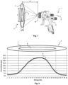
- Fig. 1 shows schematically how a spray jet or a spray pattern 3 is generated by means of a spray gun 1, which in this case is designed as a compressed air atomizing paint spray gun.
- the spray gun 1 comprises in particular a base body module 11 and a nozzle module 15, which is arranged on the base body module 11.
- the nozzle module 15, or the spray gun 1 with the nozzle module 15, generates an O-jet as described above, but the situation for an I-jet is essentially the same.
- the figure does not show a real view, but rather the spray gun 1 is shown in a side view and the spray pattern 3 in a front view of the spray pattern 3.
- the dashed lines illustrate the upper and lower outer boundaries of the generated spray jet and the upper and lower outer boundaries of the core of the spray jet.
- the Spray pattern 3 When the spray jet hits a flat object that is perpendicular to the longitudinal axis Z and at a spray distance d from the nozzle, in particular from the front end of a material nozzle of the spray gun, the Spray pattern 3 with its spray jet outer region 7 and core or core region 5.
- the outer boundary of the spray jet outer region 7 and the transition between the spray jet outer region 7 and core region 5 are fluid. However, at least the core region 5 is generally easy to identify and measure in real spray patterns.
- the core region 5 has a specific height and a specific width, which are referred to here as the spray jet cross-sectional height h and the spray jet cross-sectional width b.
- the longitudinal axis Z in this case is a longitudinal axis of the upper part of the spray gun 1, a spray axis, a nozzle longitudinal axis, or a central axis of an air cap.
- the spray jet 3 shown is different from the illustration in Fig. 1 rotated by 90°.
- the Fig. 2 shows a schematic example of a coating thickness curve over the height of the entire spray jet.
- the diagram with its graph 9, initially shows a relatively flat increase in the coating thickness in ⁇ m in the outer spray jet area 7.
- the coating thickness increases sharply, reaches its maximum, and then drops sharply again.
- graph 9 flattens out again.
- the distance between the measurement points, which form the x-axis of the diagram is not equal to 1 cm in this case.
- Fig. 3 shows a table with different exemplary nozzle modules of various nozzle module groups 10, 20, 30, 40 of an embodiment of a nozzle set according to the invention.
- the individual nozzle module groups 10, 20, 30, 40 are each outlined in bold in the table.
- the first nozzle module group 10 here comprises five nozzle modules with different nozzle sizes, in particular different nominal nozzle sizes.
- the material throughput of the five nozzle modules within the nozzle module group 10 increases from one nozzle size to the next by an equidistant value, namely 15 g/min.
- the 1.1 nozzle module has a material throughput of 135 g/min
- the 1.2 nozzle module has a material throughput of 150 g/min
- the 1.3 nozzle module has a material throughput of 165 g/min
- the 1.4 nozzle module has a material throughput of 180 g/min
- the 1.5 nozzle module has a material throughput of 195 g/min.
- All nozzle modules within the nozzle module group 10 are designed as HVLP, i.e. low-pressure nozzle modules, and all nozzle modules have the same spray jet cross-sectional height and the same spray jet cross-sectional width, whereby, as already mentioned above, the spray jet cross-sectional height h and spray jet cross-sectional width b of a nozzle module in Fig.
- the spray jet cross sections ie the core areas 5 of the spray patterns generated by the nozzle modules within the nozzle module group 10 are congruent, ie they have the same shape and size. Only the The layer thickness of the core region 5 of the spray pattern would be different due to the different material throughput.
- the spray jet cross-sectional height and spray jet cross-sectional width of the nozzle modules of nozzle module group 10 serve as a reference for the spray jet cross-sectional heights and spray jet cross-sectional widths of the nozzle modules of the other nozzle module groups and are therefore each shown at 100%.
- the nozzle modules of nozzle module group 10 are designed as the O-nozzle modules described above, i.e., they each generate a spray jet whose cross-section has a substantially oval, in particular substantially elliptical, shape.
- the user of an embodiment of a nozzle set according to the invention can thus change the nozzle size of his spray gun, i.e. he can remove the first nozzle module arranged on the base body module of the spray gun with a first nozzle size, in particular nominal nozzle size, and arrange another nozzle module of the nozzle module group 10 with a different nozzle size, in particular nominal nozzle size, on the same base body module, and obtains a spray jet with the same spray jet cross-sectional height, spray jet cross-sectional width and spray jet cross-sectional shape with a defined change in the material throughput.
- Another nozzle module group 20 also comprises five nozzle modules with different nozzle sizes, in particular different nominal nozzle sizes.
- the material throughput of the five nozzle modules within the nozzle module group 20 increases from one nozzle size to the next by an equidistant value, namely 15 g/min.
- the 1.1 nozzle module has a material throughput of 135 g/min
- the 1.2 nozzle module has a material throughput of 150 g/min
- the 1.3 nozzle module has a material throughput of 165 g/min
- the 1.4 nozzle module has a material throughput of 180 g/min
- the 1.5 nozzle module has a material throughput of 195 g/min.
- All nozzle modules within the nozzle module group 20 are designed as HVLP, ie as low-pressure nozzle modules, and all nozzle modules have the same spray jet cross-sectional height and the same spray jet cross-sectional width, whereby here too, as already mentioned above, the spray jet cross-sectional height h and spray jet cross-sectional width b of one in Fig. 1 and Fig. 2 illustrated core area 5 is meant.
- the spray jet cross sections, ie the core areas 5 of the spray patterns generated by the nozzle modules within the nozzle module group 20 are congruent, ie they have the same shape and size. Only the layer thickness of the core area 5 of the spray pattern would be different due to the different material throughput.
- the spray jet cross-sectional height of the nozzle modules of the Nozzle module group 20 is larger than the spray jet cross-sectional height of the nozzle modules of nozzle module group 10, in the present example by 6%.
- the spray jet cross-sectional width of the nozzle modules of nozzle module group 20, however, is smaller than the spray jet cross-sectional width of the nozzle modules of nozzle module group 10, in the present example it amounts to 88% of the spray jet cross-sectional width of the nozzle modules of nozzle module group 10.
- the nozzle modules of nozzle module group 20 are designed as the I-nozzle modules described above, i.e. they each generate a spray jet whose cross-section has a substantially constant width, at least in some regions.
- the user of an embodiment of a nozzle set according to the invention can thus change the nozzle size of his spray gun, i.e. he can remove the first nozzle module arranged on the base body module of the spray gun with a first nozzle size, in particular nominal nozzle size, and arrange another nozzle module of the nozzle module group 20 with a different nozzle size, in particular nominal nozzle size, on the same base body module, and obtains a spray jet with the same spray jet cross-sectional height, spray jet cross-sectional width and spray jet cross-sectional shape with a defined change in the material throughput.
- Another nozzle module group 30 also comprises five nozzle modules with different nozzle sizes, in particular different nominal nozzle sizes.
- the material throughput of the five nozzle modules within the nozzle module group 30 increases from one nozzle size to the next by an equidistant value, namely 15 g/min.
- the 1.1 nozzle module has a material throughput of 155 g/min
- the 1.2 nozzle module has a material throughput of 170 g/min
- the 1.3 nozzle module has a material throughput of 185 g/min
- the 1.4 nozzle module has a material throughput of 200 g/min
- the 1.5 nozzle module has a material throughput of 215 g/min.
- All nozzle modules within the nozzle module group 30 are designed as compliant, ie as high-pressure nozzle modules according to the above understanding, and all nozzle modules have the same spray jet cross-sectional height and the same spray jet cross-sectional width, whereby here too, as already mentioned above, the spray jet cross-sectional height h and spray jet cross-sectional width b of one in Fig. 1 and Fig. 2 illustrated core area 5 is meant.
- the spray jet cross sections, ie the core areas 5 of the spray patterns generated by the nozzle modules within the nozzle module group 30, are congruent, ie they have the same shape and size. Only the layer thickness of the core area 5 of the spray pattern would be different due to the different material throughput.
- the spray jet cross-sectional height of the nozzle modules of the Nozzle module group 30 is larger than the spray jet cross-sectional height of the nozzle modules of nozzle module group 10, in the present example by 15%.
- the spray jet cross-sectional width of the nozzle modules of nozzle module group 30 is equal to the spray jet cross-sectional width of the nozzle modules of nozzle module group 10.
- the nozzle modules of nozzle module group 30 are designed as the O-nozzle modules described above, i.e., they each generate a spray jet whose cross-section has a substantially oval, in particular substantially elliptical, shape.
- the user of an embodiment of a nozzle set according to the invention can thus change the nozzle size of his spray gun, i.e. he can remove the first nozzle module arranged on the base body module of the spray gun with a first nozzle size, in particular nominal nozzle size, and arrange another nozzle module of the nozzle module group 30 with a different nozzle size, in particular nominal nozzle size, on the same base body module, and obtains a spray jet with the same spray jet cross-sectional height, spray jet cross-sectional width and spray jet cross-sectional shape with a defined change in the material throughput.
- Another nozzle module group 40 also comprises five nozzle modules with different nozzle sizes, in particular different nominal nozzle sizes.
- the material throughput of the five nozzle modules within the nozzle module group 40 increases from one nozzle size to the next by an equidistant value, namely 15 g/min.
- the 1.1 nozzle module has a material throughput of 155 g/min
- the 1.2 nozzle module has a material throughput of 170 g/min
- the 1.3 nozzle module has a material throughput of 185 g/min
- the 1.4 nozzle module has a material throughput of 200 g/min
- the 1.5 nozzle module has a material throughput of 215 g/min.
- All nozzle modules within the nozzle module group 40 are designed as compliant, ie as high-pressure nozzle modules according to the above understanding, and all nozzle modules have the same spray jet cross-sectional height and the same spray jet cross-sectional width, whereby here too, as already mentioned above, the spray jet cross-sectional height h and spray jet cross-sectional width b of one in Fig. 1 and Fig. 2 illustrated core area 5 is meant.
- the spray jet cross-sections, ie the core areas 5 of the spray patterns generated by the nozzle modules within the nozzle module group 40 are congruent, ie they have the same shape and size. Only the layer thickness of the core area 5 of the spray pattern would be different due to the different material throughput.
- the spray jet cross-sectional height of the nozzle modules of the nozzle module group 40 is greater than the spray jet cross-sectional height of the nozzle modules of the Nozzle module group 10, in the present example 20% larger.
- the spray jet cross-sectional width of the nozzle modules of nozzle module group 40 is smaller than the spray jet cross-sectional width of the nozzle modules of nozzle module group 10; in the present example, it amounts to 88% of the spray jet cross-sectional width of the nozzle modules of nozzle module group 10.
- the nozzle modules of nozzle module group 40 are designed as the I-nozzle modules described above, i.e., they each generate a spray jet whose cross-section has a substantially constant width, at least in some regions.
- the user of an embodiment of a nozzle set according to the invention can thus change the nozzle size of his spray gun, i.e. he can remove the first nozzle module arranged on the base body module of the spray gun with a first nozzle size, in particular nominal nozzle size, and arrange another nozzle module of the nozzle module group 40 with a different nozzle size, in particular nominal nozzle size, on the same base body module, and obtains a spray jet with the same spray jet cross-sectional height, spray jet cross-sectional width and spray jet cross-sectional shape with a defined change in the material throughput.
- a nozzle set according to the invention for a spray gun in particular a compressed air atomizing paint spray gun, can comprise at least two, preferably at least four, different nozzle modules from the same nozzle module group for optional attachment in or on one and the same base body module of a spray gun, which provides the user with the aforementioned advantages.
- a nozzle set according to the invention can additionally comprise at least two, preferably at least four, different nozzle modules from one or more other nozzle module groups for optional attachment in or to one and the same base body module.
- a nozzle set according to the invention can comprise at least two, preferably at least four, different nozzle modules from nozzle module group 10 and at least two, preferably at least four, different nozzle modules from nozzle module group 20 and/or at least two, preferably at least four, different nozzle modules from nozzle module group 30 and/or at least two, preferably at least four, different nozzle modules from nozzle module group 40.
- a nozzle set according to the invention can alternatively comprise, for example, at least two, preferably at least four, different nozzle modules from the nozzle module group 20 and at least two, preferably at least four, different nozzle modules from the nozzle module group 30 and/or at least two, preferably at least four, different nozzle modules from the nozzle module group 40.
- a nozzle set according to the invention can alternatively comprise, for example, at least two, preferably at least four, different nozzle modules from the nozzle module group 30 and at least two, preferably at least four, different nozzle modules from the nozzle module group 40.
- a nozzle set according to the invention can preferably comprise at least two, preferably at least four, different nozzle modules from three different nozzle module groups, but a nozzle set according to the invention particularly preferably comprises at least two, preferably at least four, different nozzle modules from all four different nozzle module groups.
- each of the different nozzle modules from the different nozzle module groups can be arranged interchangeably on one and the same base module.
- all nozzle modules from the different nozzle module groups have the same connection.
- each nozzle module of a nozzle module group can be assigned to a nozzle module of at least one other nozzle module group, which has the same material throughput under the same spraying conditions.
- nozzle modules with the same nozzle size have the same material throughput.
- the 1.1 HVLP-O nozzle module has the same material throughput of 135 g/min as the 1.1 HVLP-I nozzle module
- the 1.2 HVLP-O nozzle module has the same material throughput as the 1.2 HVLP-I nozzle module, and so on. The same applies to the compliant nozzle modules.
- the 1.1 Compliant O-Nozzle module has the same material throughput of 155 g/min as the 1.1 Compliant I-Nozzle module
- the 1.2 Compliant O-Nozzle module has the same material throughput as the 1.2 Compliant I-Nozzle module, and so on.
- the table also shows that the spray jets that can be generated by means of the low-pressure, here HVLP nozzle modules, and the spray jets that can be generated by means of the high-pressure, here compliant nozzle modules, can have the same cross-sectional shape, in particular such that the spray jets that can be generated by means of the low-pressure nozzle modules and the spray jets that can be generated by means of the high-pressure nozzle modules have a cross-section with a substantially constant width, at least in some areas (I-nozzle modules) or a cross-section with a substantially oval, in particular essentially elliptical, shape (O-nozzle modules).
- the user can exchange a nozzle module from nozzle module group 20 for a nozzle module from nozzle module group 40, and thus switch from the low-pressure, in particular HVLP, spraying process to the high-pressure, in particular compliant, spraying process, without having to forego the I-jet that is ideal for their working method.
- the present nozzle set according to the invention has the further advantage that the user can, for example, exchange a nozzle module from nozzle module group 10 for a nozzle module from nozzle module group 20, and thus replace a nozzle module that generates an O-jet, which enables rapid application, with a nozzle module that generates an even more controllable I-jet, without having to forego the desired HVLP spray printing process and, in particular, without having to accept changes in material throughput.
- a change from a nozzle module from nozzle module group 30 to a nozzle module from nozzle module group 40 is possible without having to forego the desired compliant spray printing process and, in particular, without having to accept changes in material throughput.
- reverse changes are also possible.
- the user can use the nozzle set according to the invention to select the ideal nozzle module for his painting task and his working method.
- a selection of the ideal nozzle module is possible based on various factors, in particular based on the previously used nozzle module of a nozzle set according to the invention, the previously used nozzle module of another nozzle set, the desired spray pressure method, the spray gun model to be used, the manufacturer of the spray gun to be used, the type of medium to be sprayed, the viscosity of the medium to be sprayed, the recommendation of the manufacturer of the medium to be sprayed, the desired spray jet shape, the required layer thickness, the climatic conditions, in particular the temperature and the relative humidity within the paint booth, based on whether the user attaches greater importance to the painting speed or to good controllability of the application, and/or on the desired nozzle size.
- the inventive method for selecting a nozzle module from a Nozzle set for a painting task the selection system according to the invention and/or the computer program product according to the invention
- Fig. 4 shows a sectional view of a first air cap 55 of a nozzle module of an embodiment of a nozzle set according to the invention.
- the air cap 55 has a first horn 68 and a second horn 70.
- a vertical axis L is perpendicular to the central axis Z of the first air cap 55, wherein the central axis Z runs through the center of the central opening 80.
- the central axis A of an outer horn air outlet channel 57 forms a certain angle with the vertical axis L
- the central axis B of an inner horn air outlet channel 59 forms a further angle with the vertical axis L.
- the majority of the horn air flowing from the outer horn air outlet opening 57a of the outer horn air outlet channel 57 follows the central axis A of the outer horn air outlet channel 57, or that the center of this horn air jet lies on the central axis A of the outer horn air outlet channel 57.
- the majority of the horn air flowing from the inner horn air outlet opening 59a of the inner horn air outlet duct 59 follows the central axis B of the inner horn air outlet duct 59, or that the center of this horn air jet lies on the central axis B of the inner horn air outlet duct 59.
- the angle that the central axis A of the outer horn air outlet duct 57 forms with the vertical axis L can therefore be considered the outer horn air outlet angle W1
- the angle that the central axis B of the inner horn air outlet duct 59 forms with the vertical axis L can be considered the inner horn air outlet angle W3.
- the horn air outlet ducts of the second horn 70 opposite the aforementioned horn air outlet ducts form the same angle with the vertical axis L.
- Fig. 4 Also visible are the outer control bore 61 and the inner control bore 63, which have an outer control bore distance Y7 and an inner control bore distance Y9 to the central axis Z of the first air cap 55.
- Fig. 5 a sectional view of a second air cap 155 of another nozzle module of an embodiment of a nozzle set according to the invention.
- the air cap 155 has a first horn 168 and a second horn 170.
- the vertical axis L is also perpendicular to the central axis Z of the second air cap 155, wherein the central axis Z runs through the center of the central opening 180.
- the central axis C of an outer horn air outlet channel 157 forms a certain angle with the vertical axis L
- the central axis D of an inner horn air outlet channel 159 forms a further angle with the vertical axis L.
- the majority of the horn air flowing from the outer horn air outlet opening 157a of the outer horn air outlet channel 157 follows the central axis C of the outer horn air outlet channel 157, or that the center of this horn air jet lies on the central axis C of the outer horn air outlet channel 157.
- the majority of the horn air flowing from the inner horn air outlet opening 159a of the inner horn air outlet channel 159 follows the central axis D of the inner horn air outlet channel 159, or that the center of this horn air jet lies on the central axis D of the inner horn air outlet channel 159.
- the angle that the central axis C of an outer horn air outlet channel 157 forms with the vertical axis L can therefore be considered the outer horn air outlet angle W101, and the angle that the central axis D of an inner horn air outlet channel 159 forms with the vertical axis L can be considered the inner horn air outlet angle W103.
- the horn air outlet channels of the second horn 170 opposite the aforementioned horn air outlet channels form the same angles with the vertical axis L.
- Fig. 5 Also visible is an outer control bore 161, which has an outer control bore distance Y107 to the central axis Z of the second air cap 155. Since the control bores in this air cap 155 are arranged in the shape of a triangle, with one tip of the triangle being aligned in the direction of the inner or outer horn air outlet openings, i.e.
- the inner control hole distance Y109 is the distance between the central axis Z and an axis parallel to this central axis Z through a projection of the center of the corresponding control hole onto the section plane.
- the sum of the angles W1 plus W3 can be different than the sum of the angles W101 plus W103 for another nozzle module with the air cap 155.
- the nozzle modules can belong to the same nozzle module group.
Landscapes
- Nozzles (AREA)
- Application Of Or Painting With Fluid Materials (AREA)
Claims (2)
- Procédé pour la conception d'un module de buse (15) pour un jeu de buses pour un pistolet de pulvérisation (1), en particulier un pistolet de pulvérisation de peinture à atomisation d'air comprimé, comprenant au moins un groupe de modules de buses (10, 20, 30, 40) comportant au moins deux, de préférence au moins quatre, modules de buses (15) différents pour le montage au choix dans ou sur un seul et même module de corps de base (11) d'un pistolet de pulvérisation (1), dans lequel les modules de buses (15) sont conçus de telle sorte qu'ils ont des débits de matière différents dans les mêmes conditions de pulvérisation, dans lequel les modules de buse (15) sont conçus de telle sorte que les jets de pulvérisation pouvant être produits au moyen des modules de buse (15) possèdent essentiellement la même hauteur de section transversale de jet de pulvérisation (h) et la même largeur de section transversale de jet de pulvérisation (b), en particulier les sections transversales de jet de pulvérisation des différents modules de buse (15) sont identiques, caractérisé en ce que le procédé présente au moins les étapes suivantes :- détermination d'au moins une hauteur de section transversale de jet de pulvérisation (h) et/ou d'une largeur de section transversale de jet de pulvérisation (b) d'un jet de pulvérisation à produire par le module de buse (15),- construction du module de buse (15) qui produit un jet de pulvérisation comportant la hauteur de section transversale de jet de pulvérisation (h) et/ou la largeur de section transversale de jet de pulvérisation (b) déterminées, dans lequel le procédé comprend la construction d'un chapeau d'air (55, 155), dans lequel la construction du chapeau d'air (55, 155) comprend l'ajustement d'un angle de sortie d'air de corne externe (W1, W101) et/ou d'un angle de sortie d'air de corne interne (W3, W103) et/ou d'une distance de trou de commande (Y7, Y9, Y107, Y109) à un débit de matériau et/ou à une pression interne de buse du module de buse (15), dans lequel l'angle de sortie d'air de corne externe (W1, W101) est l'angle selon lequel l'air de corne sort depuis un orifice d'air de corne extérieur (57a, 157a) du chapeau d'air (55, 155) par rapport à un axe vertical (L), dans lequel l'axe vertical (L) est perpendiculaire à un axe central (Z) du chapeau d'air (55, 155), dans lequel l'angle de sortie d'air de corne intérieur (W3, W103) est l'angle selon lequel l'air de corne sort d'un orifice de sortie d'air de corne interne (59a, 159a) du chapeau d'air (55, 155) par rapport à l'axe vertical (L), et dans lequel la distance de trou de commande (Y7, Y9, Y107, Y109) est la distance entre au moins un trou de commande (61, 63, 161, 163) dans le chapeau d'air et une ouverture centrale (80, 180) dans le chapeau d'air (55, 155).
- Procédé selon la revendication 1, caractérisé en ce que le procédé comprend la fabrication du module de buse (15).
Applications Claiming Priority (1)
| Application Number | Priority Date | Filing Date | Title |
|---|---|---|---|
| PCT/DE2018/100679 WO2018184636A2 (fr) | 2018-08-01 | 2018-08-01 | Jeu de buses pour un pistolet pulvérisateur, système de pistolet pulvérisateur, procédé de réalisation d'un module de buses, procédé de sélection d'un module de buses d'un jeu de buses pour un travail de peinture, système de sélection et produit-programme informatique |
Publications (2)
| Publication Number | Publication Date |
|---|---|
| EP3829778A2 EP3829778A2 (fr) | 2021-06-09 |
| EP3829778B1 true EP3829778B1 (fr) | 2025-06-18 |
Family
ID=63311740
Family Applications (1)
| Application Number | Title | Priority Date | Filing Date |
|---|---|---|---|
| EP18758803.3A Active EP3829778B1 (fr) | 2018-08-01 | 2018-08-01 | Jeu de buses pour un pistolet pulvérisateur, système de pistolet pulvérisateur, procédé de réalisation d'un module de buses, procédé de sélection d'un module de buses d'un jeu de buses pour un travail de peinture, système de sélection et produit-programme informatique |
Country Status (5)
| Country | Link |
|---|---|
| US (1) | US11826771B2 (fr) |
| EP (1) | EP3829778B1 (fr) |
| CN (1) | CN112533705B (fr) |
| DE (1) | DE112018007865A5 (fr) |
| WO (1) | WO2018184636A2 (fr) |
Families Citing this family (6)
| Publication number | Priority date | Publication date | Assignee | Title |
|---|---|---|---|---|
| DE102018118738A1 (de) | 2018-08-01 | 2020-02-06 | Sata Gmbh & Co. Kg | Grundkörper für eine Spritzpistole, Spritzpistolen, Spritzpistolen-Set, Verfahren zur Herstellung eines Grundkörpers für eine Spritzpistole und Verfahren zum Umrüsten einer Spritzpistole |
| DE102018118737A1 (de) | 2018-08-01 | 2020-02-06 | Sata Gmbh & Co. Kg | Düse für eine Spritzpistole, Düsensatz für eine Spritzpistole, Spritzpistolen und Verfahren zur Herstellung einer Düse für eine Spritzpistole |
| DE102018122004A1 (de) | 2018-09-10 | 2020-03-12 | Sata Gmbh & Co. Kg | Lackierpistole, Materialauftragssystem und Verfahren zu dessen Betrieb |
| DE102020106172A1 (de) | 2020-03-06 | 2021-09-09 | Sata Gmbh & Co. Kg | Spritzpistole, insbesondere druckluftzerstäubende Farbspritzpistole, insbesondere handgeführte druckluftzerstäubende Farbspritzpistole |
| DE102020123769A1 (de) | 2020-09-11 | 2022-03-17 | Sata Gmbh & Co. Kg | Dichtelement zum Abdichten eines Übergangs zwischen einem Grundkörper einer Spritzpistole und einem Anbauteil einer Spritzpistole, Anbauteil, insbesondere Farbdüsenanordnung, für eine Spritzpistole und Spritzpistole, insbesondere Farbspritzpistole |
| TWI814473B (zh) * | 2022-07-08 | 2023-09-01 | 華景電通股份有限公司 | 噴嘴 |
Family Cites Families (648)
| Publication number | Priority date | Publication date | Assignee | Title |
|---|---|---|---|---|
| US548816A (en) | 1895-10-29 | Apparatus for manufacturing gas | ||
| US327260A (en) | 1885-09-29 | Series of labels for tacks | ||
| US459432A (en) | 1891-09-15 | Oven for baking japanned ware | ||
| DE460381C (de) | 1928-05-25 | Ernst Koerber | Rohrverbindung | |
| US552715A (en) | 1896-01-07 | lugrin | ||
| US563505A (en) | 1896-07-07 | Can-cleaner | ||
| US581107A (en) | 1897-04-20 | emery | ||
| US552213A (en) | 1895-12-31 | Speed-indicating alarm | ||
| CA521511A (fr) | 1956-02-07 | P. Dalrymple William | Pistolets | |
| US459433A (en) | 1891-09-15 | Herbert g | ||
| US40433A (en) | 1863-10-27 | Improved lubricator | ||
| US574880A (en) | 1897-01-12 | John s | ||
| US644803A (en) | 1899-10-06 | 1900-03-06 | Henry D Justi | Artificial tooth-crown. |
| US672012A (en) | 1900-01-17 | 1901-04-16 | Wilhelm Adolph August Roeper | Registering apparatus for use in connection with lifting or hoisting devices. |
| DE212979C (fr) | 1909-01-08 | 1909-09-06 | ||
| DE259621C (de) | 1912-09-20 | 1913-05-09 | Leipiziger Tangier-Manier | Einrichtung zum Steuern eines Preßluftspritzapparates , bei dem die Nadelstange an einem Kolben Sitzt. |
| US1711221A (en) | 1921-04-04 | 1929-04-30 | George R Blakeslee | Washing machine |
| US1703383A (en) | 1922-12-29 | 1929-02-26 | Matthews W N Corp | Spray gun |
| US1703384A (en) | 1924-10-18 | 1929-02-26 | Matthews W N Corp | Paint gun |
| GB259721A (fr) | 1924-11-10 | |||
| US1662496A (en) | 1926-08-16 | 1928-03-13 | Edward F Forsgard | Dishwashing machine |
| DE510362C (de) | 1929-11-15 | 1930-10-18 | Karl Ludwig Dipl Ing | Verfahren zur Herstellung von Spritzpistolen |
| US1889201A (en) | 1931-05-09 | 1932-11-29 | Joseph E Holveck | Spray nozzle |
| DE611325C (de) | 1932-05-28 | 1935-03-27 | Knorr Bremse Akt Ges | Spritzduese fuer die Zerstaeubung von Farbstoff und aehnlichen Fluessigkeiten |
| US2008381A (en) | 1933-12-05 | 1935-07-16 | George R Beeg | Dispensing device |
| FR789762A (fr) | 1934-08-06 | 1935-11-06 | Laiterie Des Fermiers Reunis | Raccord rapide pour tuyauteries destinées aux liquides alimentaires |
| US2004303A (en) | 1934-09-04 | 1935-06-11 | Binks Mfg Co | Spray gun |
| US2049700A (en) | 1935-07-15 | 1936-08-04 | Binks Mfg Co | Air nozzle for flat-spraying appliances |
| US2051210A (en) | 1935-09-13 | 1936-08-18 | Binks Mfg Co | Air nozzle for spray appliances |
| US2070696A (en) | 1935-12-11 | 1937-02-16 | Vilbiss Co | Spray head |
| US2204599A (en) | 1936-01-09 | 1940-06-18 | Jenkins Alexander Frederick | Spray gun |
| AT153883B (de) | 1936-11-23 | 1938-07-25 | Seyboth Feuerung G M B H | Vorschubplan- oder Schrägrost. |
| US2125445A (en) | 1937-02-05 | 1938-08-02 | Worthington Pump & Mach Corp | Spray nozzle |
| US2116036A (en) | 1937-04-14 | 1938-05-03 | Charles R Terry | Lock nut |
| CH203668A (de) | 1937-05-27 | 1939-03-31 | Allgaeuer Alpenmilch Aktienges | Gefäss zur Vakuumkonservierung, insbesondere von Lebens- und Genussmitteln. |
| US2198441A (en) | 1937-08-28 | 1940-04-23 | Lewis Co G B | Golf ball washer |
| US2269057A (en) | 1938-01-10 | 1942-01-06 | Alexander F Jenkins | Spraying device |
| US2356865A (en) | 1942-06-06 | 1944-08-29 | Amen David Abbott | Spray gun |
| US2416923A (en) | 1943-08-30 | 1947-03-04 | Alexander Milburn Company | Spray gun |
| US2557593A (en) | 1944-04-26 | 1951-06-19 | Atlas Diesel Ab | Operating mechanism for spray guns |
| US2416856A (en) | 1945-03-26 | 1947-03-04 | Thomsen Hugo | Binder |
| US2559091A (en) | 1945-12-01 | 1951-07-03 | Mizzy Inc | Method and solution for producing insecticidal aerosols |
| AT163577B (de) | 1946-01-21 | 1949-07-25 | Reichert Optische Werke Ag | Wälzkörperführung für Mikroskope und ähnliche optische Instrumente |
| US2612899A (en) | 1946-11-09 | 1952-10-07 | Inland Mfg Co | Radiator back flush and cleaning booth |
| US2533953A (en) | 1947-09-08 | 1950-12-12 | Vilbiss Co | Spray gun |
| US2470718A (en) | 1947-09-08 | 1949-05-17 | Vilbiss Co | Spray gun |
| US2557606A (en) | 1948-02-12 | 1951-06-19 | Atlas Diesel Ab | Adjustable stop for spray gun valve spindles |
| GB657854A (en) | 1949-03-14 | 1951-09-26 | Bylock Electric Ltd | Improvements relating to spray guns |
| US2646314A (en) | 1950-10-19 | 1953-07-21 | Vilbiss Co | Spray nozzle |
| US2609961A (en) | 1951-06-01 | 1952-09-09 | Sisto V Sapien | Air vent and cleaner therefor |
| US2721004A (en) | 1953-06-16 | 1955-10-18 | Howard A Schultz | Closure |
| US2743963A (en) | 1954-05-11 | 1956-05-01 | Vilbiss Co | Spray gun air cap |
| CH200754A (de) | 1954-07-20 | 1938-10-31 | Albert Krautzberger | Verfahren zum Beeinflussen der Form des Farbstrahles von Spritzgeräten, insbesondere zum Malen, und Vorrichtung zur Ausführung des Verfahrens. |
| NL205691A (fr) | 1955-03-30 | |||
| US2844267A (en) | 1956-11-05 | 1958-07-22 | Petriccione Peter | Combined drinking straw and bottle cap |
| US3090530A (en) | 1960-06-27 | 1963-05-21 | Vilbiss Co | Air flow control for pressure feed containers |
| US3159472A (en) | 1961-01-27 | 1964-12-01 | American Air Filter Co | Electrostatic gas cleaning apparatus |
| US3213894A (en) | 1962-10-15 | 1965-10-26 | Western Electric Co | Methods of and apparatus for connecting a strand and an elongated member and methods of manufacturing such apparatus |
| US3344992A (en) | 1964-01-27 | 1967-10-03 | Edward O Norris | Spray gun |
| US3240398A (en) | 1964-03-09 | 1966-03-15 | Sharpe Mfg Company | Vented spray gun cup |
| FR1410519A (fr) | 1964-09-14 | 1965-09-10 | Système de canalisation d'arrosage par aspersion | |
| DE1273862B (de) | 1966-04-07 | 1968-07-25 | Speidel & Keller | Manometer |
| ES338787A1 (es) | 1966-04-07 | 1968-04-16 | Speidel & Keller | Mejoras en la construccion de manometros. |
| US3417650A (en) | 1966-09-26 | 1968-12-24 | Itt | Retaining ring |
| US3381845A (en) | 1967-01-03 | 1968-05-07 | Roderick B. Macdonald | Disposable plastic container for spray guns |
| US3482781A (en) | 1968-03-18 | 1969-12-09 | Sharpe Mfg Co | Spray gun with pressure gauge feature |
| US3524589A (en) | 1968-06-14 | 1970-08-18 | Paul P Pelton Jr | Liquid-spray device |
| US3527372A (en) | 1968-12-02 | 1970-09-08 | Republic Molding Corp | Container |
| US3583632A (en) | 1969-05-23 | 1971-06-08 | Binks Mfg Co | Electrostatic spray coating apparatus |
| DE1927574A1 (de) | 1969-05-30 | 1970-12-03 | Dillenberg Bergische Metall | Pastenspruehvorrichtung |
| US3656493A (en) | 1969-09-11 | 1972-04-18 | Black James | Screen washing apparatus |
| US3840143A (en) | 1970-02-10 | 1974-10-08 | Sweetheart Plastics | Threaded nestable container |
| US3645562A (en) | 1970-03-10 | 1972-02-29 | Matthew R Fandetti | Coupling device |
| US3649937A (en) | 1970-03-23 | 1972-03-14 | Rca Corp | Electronically tuned ultra high frequency television tuner |
| CH523098A (de) | 1970-04-24 | 1972-05-31 | Sebastiani Martin | Spritzpistole, insbesondere für dickflüssige Überzugsmittel |
| US3746253A (en) | 1970-09-21 | 1973-07-17 | Walberg & Co A | Coating system |
| US3714967A (en) | 1971-05-14 | 1973-02-06 | Stewart Warner Corp | Siphon paint spray cup assembly |
| BE791343A (fr) | 1971-11-16 | 1973-03-01 | Nordson Corp | Pulverisateur electrostatique |
| CH542104A (de) | 1972-05-04 | 1973-09-30 | Leeds & Micallef | Verschluss mit einer auf einem Stutzen aufschraubbaren Kappe |
| US3771539A (en) | 1972-05-19 | 1973-11-13 | Santis B De | Paint gun cleaner |
| FR2199666A6 (fr) | 1972-09-18 | 1974-04-12 | Ransburg Corp | |
| JPS49136868U (fr) | 1973-03-28 | 1974-11-25 | ||
| SE386841B (sv) | 1973-04-19 | 1976-08-23 | Atlas Copco Ab | Elektrostatisk fergspruta |
| US3857511A (en) | 1973-07-31 | 1974-12-31 | Du Pont | Process for the spray application of aqueous paints by utilizing an air shroud |
| US3848807A (en) | 1973-12-10 | 1974-11-19 | P Partida | Confining nozzle for spray gun |
| US3870223A (en) | 1974-01-07 | 1975-03-11 | Mead Corp | Double wing pocket portfolio and file folder |
| GB1463360A (en) | 1974-12-31 | 1977-02-02 | Abrasive Int Ltd | Abrading guns |
| AT345781B (de) | 1975-05-08 | 1978-10-10 | Lilly Industries Ltd | Verfahren zur herstellung von neuen 3- aminomethyl-2-phenylbicyclo (2,2,2) octanen und -octenen sowie deren saeureadditionssalzen |
| US4000915A (en) | 1975-08-04 | 1977-01-04 | Market Research Corporation Of America | Consumer diary |
| DE2650370C2 (de) | 1975-11-12 | 1986-12-04 | Kjell Ronny Zug Ekman | Verriegelbare Leitungskupplung |
| US4171091A (en) | 1976-03-26 | 1979-10-16 | Stamicarbon, B.V. | Process and device for spraying liquid |
| USD245048S (en) | 1976-06-01 | 1977-07-19 | Modular Engineering Corporation | Rotatable holder for individually dispensing paper cups or the like |
| DE2653981C3 (de) | 1976-11-27 | 1979-08-16 | J. Wagner Gmbh, 7990 Friedrichshafen | Spritzpistole |
| NL181255C (nl) | 1977-06-14 | 1987-07-16 | Bos Willem | Afsluiter voor het onttrekken van vloeibaar materiaal uit een houder. |
| USD252097S (en) | 1978-02-01 | 1979-06-12 | Ransburg Corporation | Spray gun |
| US4273293A (en) | 1978-12-20 | 1981-06-16 | Nordson Corporation | Nozzle assembly for electrostatic spray guns |
| JPS5837476Y2 (ja) | 1979-01-19 | 1983-08-24 | 株式会社明治機械製作所 | スプレ−ガン |
| DE2926286A1 (de) | 1979-06-29 | 1981-01-08 | Mueller Ernst & Co | Zweikomponenten-farbspritzpistole |
| FR2462200A1 (fr) | 1979-07-26 | 1981-02-13 | Skm Sa | Godet pour pistolet de projection de peinture |
| JPS5654328A (en) | 1979-10-11 | 1981-05-14 | Shinagawa Sokki Seisakusho:Kk | Manufacture of pressure gauge |
| IT1138756B (it) | 1980-04-29 | 1986-09-17 | Ihmels Manfred | Pistola a spruzzo azionata a pressione |
| DE8024829U1 (de) | 1980-09-17 | 1982-08-19 | Sata-Farbspritztechnik GmbH, 7140 Ludwigsburg | Farbbecher fuer farbspritzpistole |
| JPS5775246A (en) | 1980-10-29 | 1982-05-11 | Nippon Koki Kk | Split pattern type full mold casting method |
| JPS57128346A (en) | 1981-02-02 | 1982-08-09 | Honshu Paper Co Ltd | Paper for electrophotography and form |
| DE3111571C2 (de) | 1981-03-24 | 1985-12-12 | Erich 7777 Salem Roser | Sprühgerät zum Versprühen von Flüssigkeiten oder anderen fließfähigen Materialien, insbesondere Farben |
| AT384725B (de) | 1981-09-22 | 1987-12-28 | Bosch Siemens Hausgeraete | Kaffeemaschine mit einem zentrifugalfilter |
| JPS58119862A (ja) | 1982-01-11 | 1983-07-16 | サダシゲ特殊合板株式会社 | 化粧板材の製造方法 |
| USD276472S (en) | 1982-03-08 | 1984-11-20 | Harrison/Faultless Systems, Inc. | Steam cleaning machine |
| US4478370A (en) | 1982-03-19 | 1984-10-23 | Nordson Corporation | Air atomizing nozzle assembly |
| EP0092392A3 (fr) | 1982-04-16 | 1985-04-24 | Nordson Corporation | Assemblage de buse de pulvérisation à air |
| US4614300A (en) | 1982-04-19 | 1986-09-30 | E. I. Du Pont De Nemours And Company | Computerized spray machine |
| DE3214314A1 (de) | 1982-04-19 | 1983-10-20 | J. Wagner AG, 9450 Altstätten | Elektrostatische spruehvorrichtung |
| US4411387A (en) | 1982-04-23 | 1983-10-25 | Stern Donald J | Manually-operated spray applicator |
| USD278543S (en) | 1982-09-29 | 1985-04-23 | Gintz Richard A | Display notebook |
| DE3238149C2 (de) | 1982-10-14 | 1995-07-06 | Brugger Inge Geb Ritzau | Vorrichtung zum Zerstäuben von Flüssigkeiten |
| DE8231663U1 (de) | 1982-11-11 | 1983-08-18 | Hermann Behr & Sohn Gmbh & Co, 7121 Ingersheim | Duese mit anschliessender koaxialanordnung fuer eine farbspritzeinrichtung |
| US4730753A (en) | 1982-12-27 | 1988-03-15 | Champion Spark Plug Company | Paint cup vent |
| US4502629A (en) | 1983-01-18 | 1985-03-05 | Nordson Corporation | Nozzle assembly for electrostatic spray guns |
| DE3313249A1 (de) | 1983-04-13 | 1984-10-25 | Woma-Apparatebau Wolfgang Maasberg & Co Gmbh, 4100 Duisburg | Hochdruckwasserstrahl-anlage |
| US4545536A (en) | 1983-05-13 | 1985-10-08 | Yakov Avidon | Apparatus for electrostatic paint spraying |
| JPS601722A (ja) | 1983-06-17 | 1985-01-07 | Hitachi Ltd | カラ−受像管けい光面の形成方法 |
| CH661400A5 (de) | 1983-07-13 | 1987-07-15 | Luekon Eltherm App P Luescher | Apparat zum aufheizen von speisewaermeplatten. |
| US4854504A (en) | 1983-11-04 | 1989-08-08 | Graves Spray Supply Co., Inc. | Fiberglass spray nozzle |
| DE3402097A1 (de) | 1984-01-21 | 1985-08-01 | Sata-Farbspritztechnik GmbH, 7140 Ludwigsburg | Farbbecher fuer eine farbspritzpistole |
| DE3402945C2 (de) | 1984-01-28 | 1986-07-03 | Ransburg-Gema AG, St. Gallen | Elektrostatische Sprühpistole zum Sprühbeschichten |
| FR2570140B1 (fr) | 1984-09-12 | 1987-12-04 | Vynex Sa | Clou filete |
| USD293950S (en) | 1985-02-01 | 1988-01-26 | Rug Doctor, Inc. | Portable machine for wet or dry vacuum extraction |
| DE3505618A1 (de) | 1985-02-19 | 1986-08-21 | Kopperschmidt-Mueller Gmbh & Co Kg, 4800 Bielefeld | Verfahren zum beschichten von gegenstaenden mit hilfe eines spruehstrahls und vorrichtung zur durchfuehrung dieses verfahrens |
| US4917300A (en) | 1985-04-25 | 1990-04-17 | Stewart Warner Alemite Corporation | Paint spray gun |
| DE3517122C1 (de) | 1985-05-11 | 1986-05-28 | Daimler-Benz Ag, 7000 Stuttgart | Korb- oder becherförmige Aufnahmevorrichtung für Farbbehälter an Farbspritzpistolen |
| DE3526586A1 (de) | 1985-07-25 | 1987-02-05 | Bosch Gmbh Robert | Verpackungsbehaelter mit rberdruckventil |
| DE3526819A1 (de) | 1985-07-26 | 1987-02-12 | Bramlage Gmbh | Spender fuer pastoese massen |
| USD298372S (en) | 1985-08-07 | 1988-11-01 | Taylor Jr Joseph R | Spray cabinet washer for automotive machine parts, tools or the like |
| JPH0688005B2 (ja) | 1985-12-30 | 1994-11-09 | アロイ工器株式会社 | 塗装用スプレ−ガン |
| AT383910B (de) | 1986-01-27 | 1987-09-10 | Sprecher & Schuh Ag | Gekapselte hochspannungs-schaltzelle mit ausfahrbarem trennwagen |
| FR2595059B1 (fr) * | 1986-02-28 | 1988-06-17 | Sames Sa | Dispositif de pulverisation de liquide |
| US4643330A (en) | 1986-03-27 | 1987-02-17 | Owens-Illinois, Inc. | Container systems |
| US5367148A (en) | 1986-04-18 | 1994-11-22 | Cias, Inc. | Counterfeit detection using ID numbers with at least one random portion |
| US4826539A (en) | 1986-11-04 | 1989-05-02 | Harco Graphic Products, Inc. | Cleaning apparatus and method |
| US4863781A (en) | 1987-01-28 | 1989-09-05 | Kimberly-Clark Corporation | Melt transfer web |
| DE8702559U1 (de) | 1987-02-19 | 1987-09-03 | Meschenmoser, Kurt, 7992 Tettnang | Fließbecher mit variabler Luftzufuhr für Farbspritzpistolen |
| DE3708472A1 (de) | 1987-03-16 | 1988-10-06 | Zeller Plastik Koehn Graebner | Schraubteil aus kunststoff |
| DE3709543C2 (de) | 1987-03-24 | 1996-06-05 | Wagner Gmbh J | Vorrichtung zum Zerstäuben einer Flüssigkeit |
| DE3715969A1 (de) | 1987-05-13 | 1988-12-01 | Polytype Ag | Vorrichtung zum innenlackieren von hohlkoerpern, insbesondere metallischer tuben oder dosen |
| US4784184A (en) | 1987-09-01 | 1988-11-15 | Practique, Inc. | Elastic drip silencer and funnel |
| US4806736A (en) | 1987-10-05 | 1989-02-21 | Jeno F. Paulucci | Heated delivery bag |
| DE8714271U1 (de) | 1987-10-27 | 1987-12-17 | Kopperschmidt-Mueller Gmbh & Co Kg, 4800 Bielefeld | Spritz- oder Sprühpistole |
| USD305057S (en) | 1987-10-30 | 1989-12-12 | The Devilbiss Company | Spray gun |
| DE3742308A1 (de) | 1987-12-14 | 1989-06-22 | Dietrich Dipl Ing Berner | Verfahren und vorrichtung zum buendeln von halmgutballen |
| DE8802411U1 (de) | 1988-02-24 | 1989-06-29 | Keller AG für Druckmeßtechnik, Winterthur | Druckmeßvorrichtung |
| USD317085S (en) | 1988-02-25 | 1991-05-28 | Arnold Kock GmbH u. Co. KG | Textile fabric |
| USD323191S (en) | 1988-03-07 | 1992-01-14 | Nava Minano S.p.A. | Worktop element for placement on a desk surface |
| DE3808125A1 (de) | 1988-03-11 | 1989-11-23 | Man Nutzfahrzeuge Ag | Gewindeeinsatz mit kleinem aussendurchmesser fuer schrauben mit trapezgewinde |
| US4832232A (en) | 1988-04-08 | 1989-05-23 | Broccoli Anthony B | Spray gun vent |
| EP0344026B1 (fr) | 1988-04-27 | 1994-08-31 | F.A.S. | Couvercle muni d'un verseur à débit variable et d'un dispositif de mise à l'atmosphère |
| US4887747A (en) | 1988-06-08 | 1989-12-19 | Seaquist Closures, A Division Of Pittway Corporation | Two-piece, snap-action closure |
| USD314588S (en) | 1988-07-05 | 1991-02-12 | Denham Charles R | Medication record |
| US5080285A (en) | 1988-07-11 | 1992-01-14 | Toth Denis W | Automatic paint spray gun |
| USD314421S (en) | 1988-08-17 | 1991-02-05 | Iwata Air Compressor Mfg. Co., Ltd. | Air spray gun |
| US4973184A (en) | 1988-09-01 | 1990-11-27 | Salle Roger J | Writing pad organizer |
| US4901761A (en) | 1988-10-06 | 1990-02-20 | Taylor William T | Closure apparatus with pressure test device |
| US4969603A (en) | 1988-11-01 | 1990-11-13 | R. O. Norman Company, Inc. | Fluid spray system having a replaceable cartridge |
| US5064119A (en) | 1989-02-03 | 1991-11-12 | Binks Manufacturing Company | High-volume low pressure air spray gun |
| DE8902223U1 (de) | 1989-02-24 | 1989-04-06 | SATA - Farbspritztechnik GmbH & Co., 7140 Ludwigsburg | Farbspritzpistole |
| DE3906219C2 (de) | 1989-02-28 | 1997-07-10 | Sata Farbspritztechnik | Regulierventil |
| JPH02258076A (ja) | 1989-03-30 | 1990-10-18 | Iwata Tosouki Kogyo Kk | 分割可能な吹き付け装置 |
| US5165605A (en) | 1989-03-30 | 1992-11-24 | Iwata Air Compressor Mfg. Co., Ltd. | Low pressure air atomizing spray gun |
| US5042840A (en) | 1989-04-19 | 1991-08-27 | Diversey Corporation | Refillable tank car for storing and transporting fluids |
| US5170941A (en) | 1989-04-20 | 1992-12-15 | Iwata Air Compressor Mfg. Co., Ltd. | Premixing-type spray gun |
| US4989787A (en) | 1989-05-05 | 1991-02-05 | Nikkel Robert E | Liquid spray gun accessories |
| DE8905681U1 (de) | 1989-05-05 | 1989-09-28 | Huttenlocher GmbH, 7441 Neckartailfingen | Dosieradapter |
| US4946075A (en) | 1989-06-29 | 1990-08-07 | Unro Teknik Ab | Device for dispensing flowing substances |
| ATE93417T1 (de) | 1989-07-19 | 1993-09-15 | Sata Farbspritztechnik | Duesenkopf. |
| JPH063267B2 (ja) | 1989-07-27 | 1994-01-12 | テルモ株式会社 | 多方活栓 |
| JPH0372973A (ja) | 1989-08-11 | 1991-03-28 | Iwata Tosouki Kogyo Kk | 塗料供給量制御手段を有するスプレーガン |
| DE9001265U1 (de) | 1990-02-05 | 1990-04-12 | Sata - Farbspritztechnik GmbH & Co, 7140 Ludwigsburg | Düsenkopf für eine Farbspritzpistole |
| US5071074A (en) | 1990-02-12 | 1991-12-10 | Graeco Inc. | Angled spray gun |
| US5143102A (en) | 1990-03-12 | 1992-09-01 | Graymills Corporation | High pressure parts cleaner and method |
| JPH044850A (ja) | 1990-04-23 | 1992-01-09 | Shinichi Kato | 粘性食品の揚物、およびその製造方法 |
| GB9009190D0 (en) | 1990-04-24 | 1990-06-20 | Devilbiss The Company Limited | Miniature electronic pressure gauge |
| JPH0724796B2 (ja) | 1990-05-11 | 1995-03-22 | 岩田塗装機工業株式会社 | 低圧微粒化エアスプレーガン |
| US5078323A (en) | 1990-07-20 | 1992-01-07 | Wagner Spray Tech Corporation | Air valve for portable paint gun |
| EP0554346A4 (en) | 1990-10-22 | 1993-12-01 | Logitech Inc | Ultrasonic position locating method and apparatus therefor |
| JPH04176352A (ja) | 1990-11-09 | 1992-06-24 | Shinko Denso Kk | スプレーノズル |
| US5090623A (en) | 1990-12-06 | 1992-02-25 | Ransburg Corporation | Paint spray gun |
| AU637187B2 (en) | 1991-02-04 | 1993-05-20 | Willem Johannes Smith | Beverage container |
| US5119992A (en) | 1991-02-11 | 1992-06-09 | Ransburg Corporation | Spray gun with regulated pressure feed paint cup |
| US5102045A (en) | 1991-02-26 | 1992-04-07 | Binks Manufacturing Company | Apparatus for and method of metering coating material in an electrostatic spraying system |
| WO1992017342A1 (fr) | 1991-04-03 | 1992-10-15 | Memorybank, Inc. | Systeme de gestion de donnees |
| US5209405A (en) | 1991-04-19 | 1993-05-11 | Ransburg Corporation | Baffle for hvlp paint spray gun |
| US5135124A (en) | 1991-05-09 | 1992-08-04 | Hoover Universal, Inc. | Pressure lock bayonet closure |
| JPH0530749A (ja) | 1991-07-19 | 1993-02-05 | Rigaku Corp | 電源装置 |
| DE4124245C1 (fr) | 1991-07-22 | 1992-11-12 | Heinrich Stolz Gmbh & Co Kg, 5908 Neunkirchen, De | |
| US5190219A (en) | 1991-10-03 | 1993-03-02 | Copp Jr William H | Automatic spray gun |
| US5125391A (en) | 1991-10-10 | 1992-06-30 | Servolift Eastern Corporation | Heat-retaining food service container |
| US5325473A (en) | 1991-10-11 | 1994-06-28 | The Walt Disney Company | Apparatus and method for projection upon a three-dimensional object |
| JP3079213B2 (ja) | 1991-12-25 | 2000-08-21 | 清原 まさ子 | 流体機器 |
| JPH0734880B2 (ja) | 1992-02-03 | 1995-04-19 | 有限会社ミナリ | 塗装ガン |
| DE4208500C2 (de) | 1992-03-17 | 1994-05-11 | Kleinmichel Klaus Gmbh | Spritzvorrichtung zum Aufbringen eines flüssigen Mediums wie Farbe |
| US5228488A (en) | 1992-04-13 | 1993-07-20 | Fletcher Scott W | Dispensing measuring funnel |
| EP0567325B1 (fr) | 1992-04-24 | 1996-09-04 | Itw Limited | Transducteur d'essai de pression |
| USD341186S (en) | 1992-04-27 | 1993-11-09 | Albers Terry A | Spray gun |
| US5236129A (en) | 1992-05-27 | 1993-08-17 | Ransburg Corporation | Ergonomic hand held paint spray gun |
| USRE35769E (en) | 1992-05-27 | 1998-04-14 | Ransburg Corporation | Spray gun having trigger overtravel protection and maximum flow adjustment knob warning |
| US5232299A (en) | 1992-07-21 | 1993-08-03 | Better Engineering Mfg., Inc. | Parts washer |
| DE4230535C2 (de) | 1992-09-10 | 1996-06-13 | Metacap Gmbh Fabrikation Farbs | Zweikomponenten-Spritzpistole |
| US5322221A (en) | 1992-11-09 | 1994-06-21 | Graco Inc. | Air nozzle |
| CN2136077Y (zh) | 1992-11-10 | 1993-06-16 | 石纯贵 | 电动喷枪 |
| US5381962A (en) | 1992-12-10 | 1995-01-17 | Hydro-Chem Systems, Inc. | Remote controlled spraying device |
| JPH06215741A (ja) | 1993-01-19 | 1994-08-05 | Matsushita Electric Ind Co Ltd | 充電用電池取り出し装置 |
| USD353836S (en) | 1993-03-12 | 1994-12-27 | Carvelli Salvatore G | Document organizer |
| JP2769962B2 (ja) | 1993-04-21 | 1998-06-25 | アロイ工器株式会社 | 塗装に適する空気添加型噴霧装置 |
| US5344078A (en) | 1993-04-22 | 1994-09-06 | Ransburg Corporation | Nozzle assembly for HVLP spray gun |
| DE4321940C2 (de) | 1993-07-01 | 1998-07-30 | Sata Farbspritztechnik | Trocknungsdüse |
| US5443642A (en) | 1993-10-22 | 1995-08-22 | Wagner Systems Inc. | Apparatus for electrostatic spray painting |
| US5332156A (en) | 1993-10-25 | 1994-07-26 | Ransburg Corporation | Spray gun with removable cover and method for securing a cover to a spray gun |
| US5456414A (en) * | 1993-10-28 | 1995-10-10 | Ransburg Corporation | Suction feed nozzle assembly for HVLP spray gun |
| GB2283927B (en) | 1993-11-22 | 1998-01-21 | Itw Ltd | An improved spray nozzle |
| IT230511Y1 (it) | 1993-11-23 | 1999-06-07 | Claber Spa | Gruppo di erogazione multifunzione per pistola di irrigazione |
| JP3384083B2 (ja) | 1994-01-27 | 2003-03-10 | 日産自動車株式会社 | 塗装方法および装置 |
| USD365952S (en) | 1994-02-07 | 1996-01-09 | Cordon Bleu International | Display |
| JP2578313B2 (ja) | 1994-02-10 | 1997-02-05 | 神鋼鋼線工業株式会社 | 線材の巻き取り装置 |
| US5592597A (en) | 1994-02-14 | 1997-01-07 | Parametric Technology Corporation | Real-time image generation system for simulating physical paint, drawing media, and feature modeling with 3-D graphics |
| EP0744998B1 (fr) | 1994-02-18 | 1999-04-28 | ITW Limited | Tête de pulvérisation fixé à pistolet pulvérisateur de manière permanente |
| CA2143277C (fr) | 1994-04-19 | 2000-05-16 | Michael J. Kosmyna | Dispositif a peinturer par pulverisation comportant un reservoir de peinture au sommet |
| US5662444A (en) | 1994-06-08 | 1997-09-02 | Crest Products, Inc. | Fastener assembly with axially captivated washer |
| US5529245A (en) | 1994-06-23 | 1996-06-25 | Insta-Foam Products | Low cost dispenser for multi-component foams |
| US5718767A (en) | 1994-10-05 | 1998-02-17 | Nordson Corporation | Distributed control system for powder coating system |
| DE9416015U1 (de) | 1994-10-05 | 1994-11-17 | Sata-Farbspritztechnik GmbH & Co., 70806 Kornwestheim | Düsenanordnung für eine Farbspritzpistole |
| ATE153883T1 (de) | 1994-10-05 | 1997-06-15 | Sata Farbspritztechnik | Düsenanordnung für eine farbspritzpistole |
| ATE163577T1 (de) | 1994-10-13 | 1998-03-15 | Sata Farbspritztechnik | Druckluftbetriebene farbspritzpistole |
| US5588562A (en) | 1994-10-31 | 1996-12-31 | Sander; Dieter | Tamper evident resealable plastic closure |
| US5503439A (en) | 1994-12-02 | 1996-04-02 | Batesville Casket Company, Inc. | Wedge bar locking mechanism for burial casket |
| US5655714A (en) | 1994-12-08 | 1997-08-12 | Wagner Spray Tech Corporation | Pivotable syphon tube |
| US5836517A (en) | 1995-01-03 | 1998-11-17 | Ransburg Corporation | Spray gun with fluid valve |
| US5667143A (en) | 1995-01-17 | 1997-09-16 | Wanner Engineering, Inc. | Spray gun for spraying two fluids |
| US5695125A (en) | 1995-02-09 | 1997-12-09 | Teknocraft, Inc. | Dual pressure regulator having balanced regulator valves supported in sprayer handle-conformal unibody structure |
| US5725161A (en) | 1995-02-28 | 1998-03-10 | Nordson Corporation | Electrostatic coating system including improved spray gun for conductive paints |
| US6056215A (en) | 1995-03-15 | 2000-05-02 | Nordson Corporation | Electrostatic rotary atomizing spray device |
| DE19514370A1 (de) | 1995-04-18 | 1996-10-24 | Hilti Ag | Vorrichtung zum Ausbringen von in Behältern unter Druck aufbewahrten fließfähigen Massen |
| US5609302A (en) | 1995-04-19 | 1997-03-11 | Smith; William C. | Removable spray gun fluid flow assembly |
| DE19516485C2 (de) | 1995-05-05 | 1998-10-15 | Sata Farbspritztechnik | Vorrichtung zur Wahrnehmung eines Druckabfalls in einem Atemschlauch |
| USD380301S (en) | 1995-06-14 | 1997-07-01 | Dart Manufacturing Company | Accessory pocket for portfolio |
| US5584899A (en) | 1995-07-24 | 1996-12-17 | Shorts; Kevin L. | Fluid collection and filtration apparatus |
| US5853014A (en) | 1995-09-13 | 1998-12-29 | Med-O-Tech, Inc. | PC apparatus for cleaning |
| US6308991B1 (en) | 1995-10-16 | 2001-10-30 | Oberthur Gaming Technologies, Inc. | Printed document including bar code authentication system |
| JPH09117697A (ja) | 1995-10-25 | 1997-05-06 | Alloy Koki Kk | 噴霧塗装装置 |
| USD402820S (en) | 1995-11-20 | 1998-12-22 | Gorrie Advertising Management Limited | Glass cleaning center for holding water and squeegees |
| USD376637S (en) | 1995-11-22 | 1996-12-17 | Wagner Spray Tech Corporation | Spray gun |
| US5803360A (en) | 1995-11-27 | 1998-09-08 | Spitznagel; Max W. A. | Apparatus for providing enhanced spray capabilities for a gravity-fed spray gun |
| US5704381A (en) | 1996-01-25 | 1998-01-06 | Northrop Grumman Corporation | Enclosed spray gun and accessories cleaning apparatus |
| PL185822B1 (pl) | 1996-01-30 | 2003-08-29 | Crown Cork Ag | Zamknięcie pojemnikaZamknięcie pojemnika |
| EP0801002A1 (fr) | 1996-04-12 | 1997-10-15 | Plastiflac S.A. | Dispositif de transfert de fluides |
| US5829682A (en) | 1996-04-26 | 1998-11-03 | Spraying Systems Co. | Air-assisted spray nozzle assembly |
| US5762228A (en) | 1996-07-26 | 1998-06-09 | Dart Industries Inc. | Vented seal with rocking vent cover |
| US5874680A (en) | 1996-08-12 | 1999-02-23 | Moore; Randy A. | Combination in-line pressure sensor and portable gauge head |
| US5951190A (en) | 1996-08-16 | 1999-09-14 | Specialty Loose Leaf, Inc. | Pocket loose-leaf binder |
| US6050499A (en) | 1996-12-03 | 2000-04-18 | Abb K. K. | Rotary spray head coater |
| DE19650781A1 (de) | 1996-12-06 | 1998-06-10 | Itw Oberflaechentechnik Gmbh | Sprühbeschichtungseinrichtung |
| US5816501A (en) | 1996-12-16 | 1998-10-06 | Ransburg Corporation | Disposable paint container liner and method |
| EP1961488B2 (fr) | 1997-01-24 | 2021-02-24 | 3M Company | Appareil de vaporisation de liquides, conteneurs jetables et doublures adaptés à son utilisation |
| US6820824B1 (en) | 1998-01-14 | 2004-11-23 | 3M Innovative Properties Company | Apparatus for spraying liquids, disposable containers and liners suitable for use therewith |
| USD391403S (en) | 1997-02-11 | 1998-03-03 | Josephs Ira A | Camouflage pattern applied to sheet material |
| US5954268A (en) | 1997-03-03 | 1999-09-21 | Joshi; Ashok V. | Fluid delivery system |
| US6019294A (en) | 1997-05-23 | 2000-02-01 | Graco Inc | Interchangeable feed airspray/HVLP spray gun |
| AU133969S (en) | 1997-06-09 | 1998-06-03 | Anest Iwata Corp | Air spray gun |
| US6203068B1 (en) | 1997-06-18 | 2001-03-20 | Glenn Petkovsek | Special service mailing assembly with label, tracking area and receipt and a method for preparing a mailpiece for delivery |
| DE19727884B4 (de) | 1997-07-01 | 2005-06-23 | Sata Farbspritztechnik Gmbh & Co.Kg | Vorrichtung zur Befeuchtung von Luft |
| US6442276B1 (en) | 1997-07-21 | 2002-08-27 | Assure Systems, Inc. | Verification of authenticity of goods by use of random numbers |
| US5992763A (en) | 1997-08-06 | 1999-11-30 | Vortexx Group Incorporated | Nozzle and method for enhancing fluid entrainment |
| US5941461A (en) | 1997-09-29 | 1999-08-24 | Vortexx Group Incorporated | Nozzle assembly and method for enhancing fluid entrainment |
| US5884006A (en) | 1997-10-17 | 1999-03-16 | Frohlich; Sigurd | Rechargeable phase change material unit and food warming device |
| US5951296A (en) | 1997-11-06 | 1999-09-14 | University Of Northern Iowa Foundation (Unif) | Optical spray painting practice and training system |
| USD405503S (en) | 1997-11-07 | 1999-02-09 | Anest Iwata Kabushikikaisha | Hand held air spray gun |
| US6056213A (en) | 1998-01-30 | 2000-05-02 | 3M Innovative Properties Company | Modular system for atomizing a liquid |
| FR2774928B1 (fr) | 1998-02-17 | 2000-03-31 | Injelec | Element et dispositif d'alimentation pour pistolet de projection d'un liquide, et pistolet correspondant |
| US6091053A (en) | 1998-02-19 | 2000-07-18 | Sataco Co., Ltd | Heat-reserving container for pizza and furnace for the same |
| DE19807973C1 (de) | 1998-02-25 | 1999-07-29 | Wagner Int | Spritzvorrichtung zum Zerstäuben von Flüssigkeiten |
| US6089471A (en) | 1998-03-25 | 2000-07-18 | Accuspray, Inc. | Fluid spray gun |
| DE19824264C2 (de) | 1998-06-02 | 2001-08-30 | Sata Farbspritztechnik | Tragbare Atemschutzvorrichtung |
| JP3770444B2 (ja) | 1998-06-30 | 2006-04-26 | 株式会社吉野工業所 | トリガー式液体噴出容器 |
| DE19832990B4 (de) | 1998-07-22 | 2006-04-20 | Schreiner Etiketten Und Selbstklebetechnik Gmbh & Co. | Etikett und Verfahren zum Verdecken von Informationen |
| US5979797A (en) | 1998-08-14 | 1999-11-09 | Castellano; Michael A. | Handheld pressurized hopper gun and method |
| JP3730027B2 (ja) | 1998-08-27 | 2005-12-21 | 株式会社吉野工業所 | トリガー式液体噴出容器 |
| FR2783440B1 (fr) | 1998-09-18 | 2001-02-23 | Michel Camilleri | Godet cylindrique jetable pour la preparation ou le melange de peintures utilisable comme godet de pistolet a peinture |
| US6089607A (en) | 1998-09-30 | 2000-07-18 | Alliance Marketing Concepts, L.C. | Calendar and appointment journal |
| US6460787B1 (en) | 1998-10-22 | 2002-10-08 | Nordson Corporation | Modular fluid spray gun |
| USD414636S (en) | 1998-10-28 | 1999-10-05 | Henschel-Steinau, Inc. | Tubular display and dispenser |
| US6010082A (en) | 1998-11-17 | 2000-01-04 | Peterson; Kurt E. | In-line point of use filter with restrictor valve and gauge port |
| FR2788231B1 (fr) | 1999-01-11 | 2001-03-09 | Itw Surfaces & Finitions | Tete de pulverisation d'un produit tel que de la peinture |
| US6039218A (en) | 1999-01-11 | 2000-03-21 | Innovative Plastic Technology, Inc. | Tamper-evident closure with abutment |
| EP1152948A4 (fr) | 1999-01-19 | 2003-02-12 | Volusia Holding Corp | Marqueur pour tuyaux, conduits, tubes et tiges |
| US6036109A (en) | 1999-02-01 | 2000-03-14 | Campbell Hausfeld/Scott Fetzer Company | Indexing aircap retaining ring |
| AU768928B2 (en) | 1999-02-12 | 2004-01-08 | Robert Dymock Mcintyre | Improvements in feeder bottles |
| JP4422851B2 (ja) | 1999-03-17 | 2010-02-24 | キヤノン株式会社 | 座標入力装置及び方法 |
| US6171544B1 (en) * | 1999-04-02 | 2001-01-09 | Praxair Technology, Inc. | Multiple coherent jet lance |
| DE19918257A1 (de) | 1999-04-22 | 2000-11-23 | Lechler Gmbh & Co Kg | Hochdrucksprühdüse |
| US6435426B1 (en) | 1999-05-11 | 2002-08-20 | William H. Copp, Jr. | Floating gasket plate for paint cup on spray gun |
| USD459433S1 (en) | 1999-05-14 | 2002-06-25 | Sata-Farbspritztechnik Gmbh&Co. | Spray gun head ring |
| DE29909950U1 (de) | 1999-06-08 | 1999-09-23 | Chang, Jen-Chih, Taichung | Spritzpistolenbehälter |
| US6267301B1 (en) | 1999-06-11 | 2001-07-31 | Spraying Systems Co. | Air atomizing nozzle assembly with improved air cap |
| DE69928944T2 (de) | 1999-06-30 | 2006-09-07 | Anest Iwata Corp., Yokohama | Niederdruck-spritzpistole |
| ES2185600T3 (es) | 1999-07-01 | 2003-05-01 | Johnson & Son Inc S C | Estacion insecticida de cebo liquido. |
| DE10001071A1 (de) | 1999-07-08 | 2001-01-11 | Boedrich Hans Joachim | Vorrichtung zum Reinigen von Farbspritzpistolen |
| US6536687B1 (en) | 1999-08-16 | 2003-03-25 | 3M Innovative Properties Company | Mixing cup adapting assembly |
| US6092740A (en) | 1999-08-20 | 2000-07-25 | Liu; Horng-Hsiang | Structure of a paint container for spray gun |
| DE19941362C2 (de) | 1999-08-31 | 2003-12-18 | Winter Ag | Datenträger und Verfahren zu dessen Herstellung |
| DE19945760A1 (de) | 1999-09-24 | 2001-03-29 | Christian Ploppa | Prüfsystem und Verfahren zum Prüfen eines Gegenstandes |
| US6250567B1 (en) | 1999-11-30 | 2001-06-26 | Rhino Linings Usa, Inc. | Apparatus and method for spraying single or multi-component material |
| DE19958569C1 (de) | 1999-12-04 | 2001-02-15 | Sata Farbspritztechnik | Farbspritzpistole |
| US6661438B1 (en) | 2000-01-18 | 2003-12-09 | Seiko Epson Corporation | Display apparatus and portable information processing apparatus |
| JP3308516B2 (ja) | 2000-03-15 | 2002-07-29 | ランズバーグ・インダストリー株式会社 | エアスプレーガン |
| JP2001286793A (ja) | 2000-04-05 | 2001-10-16 | Bb Ricchi:Kk | エアーブラシ |
| US6276616B1 (en) | 2000-04-07 | 2001-08-21 | Illinois Tool Works Inc. | Fluid needle loading assembly for an airless spray paint gun |
| US6855173B2 (en) | 2000-06-05 | 2005-02-15 | Procter & Gamble Company | Use of absorbent materials to separate water from lipophilic fluid |
| GB0015144D0 (en) | 2000-06-21 | 2000-08-09 | Scient Games International Ltd | Improved information-bearing card |
| DE10031858B4 (de) | 2000-06-30 | 2008-07-03 | Sata Gmbh & Co. Kg | Spritzpistole |
| DE10031857A1 (de) | 2000-06-30 | 2002-01-17 | Sata Farbspritztechnik | Spritzpistole |
| SE515840C3 (sv) | 2000-09-01 | 2001-10-30 | Hedson Technologies Ab | Anordning för att tvätta sprutpistoler med lösningsmedel |
| US6450422B1 (en) | 2000-09-07 | 2002-09-17 | Richard A. Maggio | Spray gun |
| USD448451S1 (en) | 2000-11-06 | 2001-09-25 | Trade Associates, Inc. | Trigger sprayer |
| DE10059406B4 (de) | 2000-11-30 | 2007-04-26 | Krautzberger Gmbh | Spritzvorrichtung |
| GB2370787A (en) | 2000-12-07 | 2002-07-10 | Jackel Int Ltd | Feeding bottle and stand |
| DE10100171B4 (de) | 2001-01-04 | 2005-02-24 | Artech Gmbh Design + Production In Plastic | Durchstechbares Verschlusselement und Tintenbehälter mit durchstechbarem Verschlusselement |
| US6435427B1 (en) * | 2001-01-16 | 2002-08-20 | Coltec Industries, Inc. | Nozzle assembly with an extendable turret |
| GB2372465B (en) | 2001-02-26 | 2004-07-14 | Itw Ltd | A spray gun |
| DE60104817T2 (de) | 2001-04-06 | 2005-09-01 | Anest Iwata Europe S.R.L. | Manuelle Sprühbeschichtungspistole |
| US6470906B1 (en) | 2001-04-12 | 2002-10-29 | Ming Don Shieh | Valve having safety structure for cutting off hot water |
| GB0110025D0 (en) | 2001-04-24 | 2001-06-13 | 3M Innovative Properties Co | Improvements in or relating to liquid spraying apparatus |
| USD457599S1 (en) | 2001-05-07 | 2002-05-21 | Graco Minnesota Inc. | Electrostatic spray gun |
| TW509113U (en) | 2001-05-15 | 2002-11-01 | Chia Chung Prec Ind Co Ltd | Automatic washing device for paint spraying gun |
| US6647997B2 (en) | 2001-05-16 | 2003-11-18 | Merrill K. Mohn | Paint gun washer |
| US6675845B2 (en) | 2001-06-05 | 2004-01-13 | The Procter & Gamble Company | Package and method for controlled metered dose dispensing of a fluid product |
| US6616189B2 (en) | 2001-06-08 | 2003-09-09 | Premier Print & Services Group, Inc. | Sequentially placed shipping and packing label system |
| US6540114B1 (en) | 2001-06-13 | 2003-04-01 | West Penn Plastic, Inc. | Dual tamper evident dispensing closure |
| NO314372B1 (no) | 2001-06-20 | 2003-03-10 | Kezzler As | Fremgangsmåte for frembringelse og senere benyttelse av autentiseringsinformasjon |
| DE10135104C1 (de) | 2001-07-19 | 2002-09-12 | Sata Farbspritztechnik | Farbspritzpistole |
| US7458612B1 (en) | 2001-08-01 | 2008-12-02 | Stamps.Com Inc. | Postal shipping label |
| JP4635391B2 (ja) | 2001-08-02 | 2011-02-23 | 株式会社デンソー | 圧力センサの取付け構造 |
| DE20114257U1 (de) | 2001-08-29 | 2002-01-10 | Herkules Hebetechnik GmbH, 34123 Kassel | Reinigungsvorrichtung für Farbspritzgeräte, z.B. Farbspritzpistolen |
| GB0122208D0 (en) | 2001-09-14 | 2001-11-07 | Vincent Ltd G | Spray gun |
| WO2003030962A2 (fr) | 2001-10-05 | 2003-04-17 | Medical Components, Inc. | Bague d'information pour catheter |
| US6717584B2 (en) | 2001-11-06 | 2004-04-06 | General Motors Corporation | Method and system for visualizing paint on a computer-generated object |
| ATE294644T1 (de) | 2001-11-14 | 2005-05-15 | Martin Ruda | Spritzpistolenbecher mit fester einlage |
| US20040217201A1 (en) | 2001-11-14 | 2004-11-04 | Martin Ruda | Spray gun container |
| GB2382071B (en) | 2001-11-20 | 2005-06-29 | Beeson & Sons Ltd | User-friendly bottle and closure thread assembly |
| TW510253U (en) | 2001-11-23 | 2002-11-11 | Kuan Chang Co Ltd | Head structure for spray gun with exchangeable nozzle |
| US6801211B2 (en) | 2001-12-21 | 2004-10-05 | Ladd B. Forsline | Computer painting system with passive paint brush stylus |
| US20030127046A1 (en) | 2002-01-09 | 2003-07-10 | Harley-Davidson Motor Company Group, Inc. | Paint spray gun cleaner |
| US6626383B1 (en) | 2002-01-16 | 2003-09-30 | James S. Campbell | Device for breaking, tearing, and crushing through plant material |
| JP3533387B2 (ja) | 2002-01-18 | 2004-05-31 | アネスト岩田株式会社 | 圧力表示スプレーガン |
| DE10205831A1 (de) | 2002-02-13 | 2003-08-28 | Sata Farbspritztechnik | Farbspritzpistole |
| JP2003261155A (ja) | 2002-03-04 | 2003-09-16 | Alcoa Closure Systems Japan Ltd | 合成樹脂製キャップ |
| US6793155B2 (en) | 2002-03-14 | 2004-09-21 | Tiao-Hsiang Huang | Spray gun pressure stabilizer |
| SE525718C2 (sv) | 2002-04-11 | 2005-04-12 | Eltex Sweden Ab | Anordning vid ett munstycke för reglering av en gas eller vätska |
| SE0201111L (sv) | 2002-04-12 | 2003-10-13 | Ecco Finishing Ab | Sprutanordning |
| GB0210446D0 (en) | 2002-05-08 | 2002-06-12 | 3M Innovative Properties Co | Conformable pouch reservoir for spray gun |
| US8025314B2 (en) | 2002-05-15 | 2011-09-27 | Target Brands, Inc. | Medication packaging and labeling system |
| FR2839663B1 (fr) | 2002-05-16 | 2004-07-23 | Itw Surfaces & Finitions | Tete de pulverisation d'un produit tel que de la peinture |
| DE20208162U1 (de) | 2002-05-24 | 2002-08-22 | Fraunhofer-Gesellschaft zur Förderung der angewandten Forschung e.V., 80636 München | System zur Erzeugung großflächiger digitaler Bilder |
| US6874664B1 (en) | 2002-06-05 | 2005-04-05 | Rexam Medical Packaging Inc. | Push-pull dispenser with folding fingers |
| DE20208915U1 (de) | 2002-06-07 | 2002-08-14 | Hsueh, Li-Wei, Nantuen Chiu, Taichung | Farbsprühgerät |
| US6763964B1 (en) | 2002-06-11 | 2004-07-20 | Pacific Market, Inc. | One hand openable lid for beverage container |
| GB2389908B (en) | 2002-06-18 | 2005-05-18 | Itw Ltd | Pressure gauge |
| USD472730S1 (en) | 2002-07-22 | 2003-04-08 | Chicago Display Marketing | Product dispenser |
| US7017834B2 (en) | 2002-08-15 | 2006-03-28 | Santa Cruz Cathy D | Liquid storage, dispensing, mixing, application, system and method of use |
| CA2402094A1 (fr) | 2002-09-10 | 2004-03-10 | Silvano Breda | Valve de derivation a orifices multiples amelioree |
| US6626382B1 (en) | 2002-10-04 | 2003-09-30 | Horng-Hsiang Liu | Spray gun air volume adjustment knob |
| US6612506B1 (en) | 2002-10-09 | 2003-09-02 | Tiao-Hsiang Huang | Spray gun head with dual air ports & a diverter bushing |
| USD474528S1 (en) | 2002-10-17 | 2003-05-13 | Tiao-Hsiang Huang | Spray gun |
| AU2003301667B2 (en) | 2002-10-22 | 2008-01-24 | Graco Minnesota Inc. | Plural component spray gun for fast setting materials |
| GB0224698D0 (en) | 2002-10-24 | 2002-12-04 | 3M Innovative Properties Co | Easy clean spray gun |
| US6547160B1 (en) | 2002-11-12 | 2003-04-15 | Tiao-Hsiang Huang | Spray gun with a stabilizing structure of air output |
| ES2279049T3 (es) | 2002-11-29 | 2007-08-16 | Anest Iwata Europe Srl | Pistola pulverizadora manual y copa desechable asociada. |
| US20040245208A1 (en) | 2002-12-02 | 2004-12-09 | Dennison Robert A. | Bottle of sprayable liquid with flexible neck |
| US20040104194A1 (en) | 2002-12-02 | 2004-06-03 | Dennison Robert A. | Bottle of sprayable liquid with flexible neck |
| USD485685S1 (en) | 2002-12-04 | 2004-01-27 | Battelle Memorial Institute | Camouflage pattern for sheet material |
| DE50307265D1 (de) | 2002-12-10 | 2007-06-21 | Martin Ruda | Einwandiger spritzpistolenbecher und verfahren zum herstellen eines deckels |
| CA2415209C (fr) | 2002-12-27 | 2008-12-09 | Seastar Chemicals Inc. | Bouchon compte-gouttes |
| US6955180B2 (en) | 2003-01-06 | 2005-10-18 | Spex Certiprep, Inc. | Pipette washer |
| US6962432B2 (en) | 2003-02-10 | 2005-11-08 | Hp Intellectual Corp. | Machine for mixing and dispensing salad dressings |
| US6874708B2 (en) | 2003-02-13 | 2005-04-05 | Illinois Tool Works Inc. | Automatic air-assisted manifold mounted gun |
| US6824074B2 (en) | 2003-02-18 | 2004-11-30 | Spraying Systems Co. | Air assisted spray nozzle assembly for spraying viscous liquids |
| JP4511371B2 (ja) | 2003-02-21 | 2010-07-28 | ジュサップ,フィリップ | 非接触スプレー器具洗浄装置 |
| US7517181B2 (en) | 2003-03-13 | 2009-04-14 | J3, Llc | Track fitting for a cargo security system |
| DE10311238A1 (de) | 2003-03-14 | 2004-10-07 | Festo Ag & Co. | Verfahren zur Herstellung eines Ventils |
| US6843390B1 (en) | 2003-03-17 | 2005-01-18 | Joe G. Bristor | Multiple fluid closed system dispensing device |
| JP2006521205A (ja) * | 2003-03-27 | 2006-09-21 | スプレイング システムズ カンパニー | 複数の制御モジュールを有するモジュール式スプレーガン |
| US7106343B1 (en) | 2003-04-08 | 2006-09-12 | Carter Hickman | Method and process for virtual paint application |
| DE10316771A1 (de) | 2003-04-10 | 2004-10-28 | Giesecke & Devrient Gmbh | Sicherheitslabel und Herstellungsverfahren für dasselbe |
| US6796514B1 (en) | 2003-05-02 | 2004-09-28 | 3M Innovative Properties Company | Pre-packaged material supply assembly |
| US20040233223A1 (en) | 2003-05-22 | 2004-11-25 | Steven Schkolne | Physical/digital input methodologies for spatial manipulations and entertainment |
| DE10323256A1 (de) | 2003-05-23 | 2004-12-16 | Walther Spritz- Und Lackiersysteme Gmbh | Spritzpistole |
| US6874656B2 (en) | 2003-06-04 | 2005-04-05 | Rieke Corporation | Vented closure |
| JP2005000735A (ja) | 2003-06-09 | 2005-01-06 | Mitani Valve Co Ltd | 内容物放出操作用のトリガレバーロック機構ならびにそのためのトリガレバーおよびストッパー |
| US6945429B2 (en) | 2003-06-10 | 2005-09-20 | Illinois Tool Works Inc. | Disposable paint cup attachment system for gravity-feed paint sprayer |
| US6712292B1 (en) | 2003-06-10 | 2004-03-30 | Illinois Tool Works Inc. | Adjustable adapter for gravity-feed paint sprayer |
| DE102004027789B4 (de) | 2003-06-11 | 2011-12-08 | Martin Ruda | Austauschbare Lackiermittelleiteinrichtung und Spritzpistole |
| DE10335420A1 (de) | 2003-08-02 | 2005-02-17 | ITW Oberflächentechnik GmbH & Co. KG | Spritzbeschichtungseinrichtung |
| FR2859118B1 (fr) | 2003-08-26 | 2007-03-09 | Michel Camilleri | Godet jetable a monter sur un pistolet pour la preparation, l'application et la conservation d'une peinture |
| US20050082828A1 (en) | 2003-09-12 | 2005-04-21 | Wicks Jeffrey C. | Releasable connection assembly for joining tubing sections |
| DE10343064A1 (de) | 2003-09-16 | 2005-05-04 | Sata Farbspritztechnik | Verfahren zur Authentifizierung eines Produkts |
| US7083119B2 (en) | 2003-09-25 | 2006-08-01 | 3M Innovative Properties Company | Security clip for spray gun connector |
| WO2005046852A2 (fr) | 2003-11-07 | 2005-05-26 | Angiotech Biomaterials Corporation | Dispositif et procede permettant de melanger et de distribuer les composants fluides d'une composition a composants multiples |
| JP3796243B2 (ja) | 2003-11-07 | 2006-07-12 | 昭和機器工業株式会社 | 液体貯蔵タンク通気管用の通気弁構造 |
| FR2863512B1 (fr) | 2003-12-10 | 2006-01-21 | Itw Surfaces & Finitions | Pistolet automatique de pulverisation |
| US7032839B2 (en) | 2003-12-30 | 2006-04-25 | 3M Innovative Properties Company | Liquid spray gun with manually separable portions |
| US7201336B2 (en) | 2003-12-30 | 2007-04-10 | 3M Innovative Properties Company | Liquid spray gun with non-circular horn air outlet passageways and apertures |
| CA2455182A1 (fr) | 2004-01-14 | 2005-07-14 | Charles Harland | Contenant pour pistolet pulverisateur |
| US7165732B2 (en) | 2004-01-16 | 2007-01-23 | Illinois Tool Works Inc. | Adapter assembly for a fluid supply assembly |
| DE102004003439B4 (de) | 2004-01-22 | 2022-02-03 | Sata Gmbh & Co. Kg | Farbbechersystem für eine Farbspritzpistole |
| DE102004003438A1 (de) | 2004-01-22 | 2005-08-18 | Sata Farbspritztechnik Gmbh & Co.Kg | Fließbecher für eine Farbspritzpistole |
| US7255293B2 (en) | 2004-02-13 | 2007-08-14 | Meadwestvaco Corporation | Hose-end sprayer assembly |
| DE102004007733B4 (de) | 2004-02-16 | 2014-02-13 | Sata Gmbh & Co. Kg | Fließbecher für eine Farbspritzpistole |
| GB2411234A (en) | 2004-02-19 | 2005-08-24 | Itw Ltd | Pressure monitoring device for a paint spray gun |
| GB0405337D0 (en) | 2004-03-09 | 2004-04-21 | Petty Robert H | Paint spraygun cleaner |
| US20050220943A1 (en) | 2004-03-10 | 2005-10-06 | Abrams Leeann | System and method for portable infant feeding |
| DE102004014646B3 (de) | 2004-03-25 | 2005-07-14 | Brita Gmbh | Behälterdeckel |
| US20050215284A1 (en) | 2004-03-26 | 2005-09-29 | Broadcom Corporation | Collaborative coexistence with dynamic prioritization of wireless devices |
| TWM255079U (en) | 2004-04-13 | 2005-01-11 | Shing-Tz Wang | Air paint spraying gun with high adhesion and low contamination |
| CN100453186C (zh) | 2004-04-29 | 2009-01-21 | 萨塔有限及两合公司 | 用于喷漆枪的可通气的流体储存器 |
| DE102004021298A1 (de) | 2004-04-29 | 2005-11-24 | Sata Farbspritztechnik Gmbh & Co.Kg | Fließbecher für eine Farbspritzpistole |
| EP1759283A4 (fr) | 2004-05-06 | 2009-11-18 | Us Postal Service | Etiquette d'adresse a partie de signature et procede d'utilisation |
| ITMI20041118A1 (it) | 2004-06-03 | 2004-09-03 | Rosauto Srl | Dispositivo di lavaggio dotato di zone di lavaggio automatico e manuale separate per pistole e spruzzo e loro componenti |
| US7511703B2 (en) | 2004-06-28 | 2009-03-31 | Microsoft Corporation | Using size and shape of a physical object to manipulate output in an interactive display application |
| US7350723B2 (en) | 2004-06-28 | 2008-04-01 | Just A Simple Thing, Inc | Cordless, self-contained, handheld spray gun |
| US7844553B2 (en) | 2004-06-30 | 2010-11-30 | Psi Systems, Inc. | Integrated shipping label and customs form |
| US7472840B2 (en) * | 2004-07-02 | 2009-01-06 | Rain Bird Corporation | Sprinkler nozzle insert assembly |
| USD519687S1 (en) | 2004-07-16 | 2006-04-25 | Zahav Ya Acov Meshi | Clip for packaging and/or marking poultry and/or meat products |
| DE102004043599B4 (de) | 2004-09-07 | 2014-11-27 | Sata Gmbh & Co. Kg | Fließbecher für eine Farbspritzpistole |
| USD541088S1 (en) | 2004-10-07 | 2007-04-24 | Joseph M. Nesci | Vitamin dispenser |
| DE102004051032B4 (de) | 2004-10-20 | 2008-02-21 | Förster, Steffen, Dipl.-Ing. | Manometer |
| US7913938B2 (en) | 2004-11-12 | 2011-03-29 | Mystic Tan, Inc. | Electrostatic spray nozzle with adjustable fluid tip and interchangeable components |
| DE102004055737B3 (de) | 2004-11-18 | 2006-05-04 | Microjet Gmbh | Steuermodul für eine Düsenanordnung |
| US20060108449A1 (en) * | 2004-11-22 | 2006-05-25 | Sodemann Wesley C | Pressurized fluid delivery apparatus and nozzle kit |
| US7389949B2 (en) | 2004-12-14 | 2008-06-24 | Briggs & Stratton Corporation | Pressure washer trigger lock |
| PL2450108T3 (pl) | 2004-12-16 | 2017-04-28 | Saint-Gobain Abrasives, Inc. | Zespół zbiornika dostarczającego ciecz i wkładki do pistoletów natryskowych |
| US7175110B2 (en) | 2004-12-21 | 2007-02-13 | Anest Iwata Corporation | Manual spray gun and associated disposable cup |
| DE202005001702U1 (de) | 2005-02-02 | 2006-06-14 | Sata Farbspritztechnik Gmbh & Co.Kg | Virtuelles Lackiersystem und Farbspritzpistole |
| US7410106B2 (en) | 2005-02-08 | 2008-08-12 | 3M Innovative Properties Company | Pressurized liquid supply assembly |
| USD528192S1 (en) | 2005-03-07 | 2006-09-12 | Cambro Manufacturing Company | Food service venting plug |
| WO2006126288A1 (fr) | 2005-05-26 | 2006-11-30 | Sadao Nozawa | Recipient pour liquide |
| US7036752B1 (en) | 2005-06-20 | 2006-05-02 | Shin Kuei Hsiang | Connection of cup and paint sprayer |
| JP5085019B2 (ja) | 2005-07-21 | 2012-11-28 | アネスト岩田株式会社 | スプレーガンのエア霧化空気キャップ |
| USD538493S1 (en) | 2005-07-22 | 2007-03-13 | Whirlpool Corporation | Wall vacuum |
| USD552715S1 (en) | 2005-07-28 | 2007-10-09 | Sata Gmbh & Co. Kg | Paint spray gun |
| US20100059533A1 (en) | 2005-08-01 | 2010-03-11 | Life Technologies Corporation | Labels, containers, system and method for providing reagents |
| USD538886S1 (en) | 2005-08-23 | 2007-03-20 | Kuan Chang Co., Ltd. | Spray gun body |
| US7097118B1 (en) | 2005-09-15 | 2006-08-29 | Kuan Chang Co., Ltd. | Spray paint gun with shunt control |
| US20070095943A1 (en) | 2005-10-28 | 2007-05-03 | Turnbull William N | Liquid reservoir, and kit, spray assembly and method using same |
| US8616434B2 (en) | 2006-02-28 | 2013-12-31 | Wilopen Products, Lc | Multi-component forms |
| US20070205305A1 (en) | 2006-03-03 | 2007-09-06 | Rbl Products, Inc. | Paint spray system |
| USD554703S1 (en) | 2006-03-03 | 2007-11-06 | Steve Josephson | Notepad holder |
| USD538050S1 (en) | 2006-03-09 | 2007-03-13 | Randy Scott Tardif | Substrate with camouflage pattern |
| USD545943S1 (en) | 2006-03-14 | 2007-07-03 | Illinois Tool Works Inc. | Coating material dispensing device |
| WO2007126998A2 (fr) | 2006-03-29 | 2007-11-08 | Spraying Systems Co. | Pistolet de pulvérisation portatif à gachette |
| US20070252378A1 (en) | 2006-04-17 | 2007-11-01 | Walgreen Co. | Pharmacy label and method for preparation |
| US20070262169A1 (en) | 2006-05-01 | 2007-11-15 | Chia Chung Precision Industrial Co., Ltd. | Spray head structure of a spray gun |
| CA2651721C (fr) | 2006-05-04 | 2011-04-12 | Brasscorp Limited | Point de controle |
| JP5441687B2 (ja) | 2006-05-09 | 2014-03-12 | ノードソン コーポレーション | 缶コーティングのための制御システム |
| USD541053S1 (en) | 2006-06-01 | 2007-04-24 | The Procter & Gamble Company | Surface pattern of a paper product |
| USD573227S1 (en) | 2006-06-12 | 2008-07-15 | Titan Tool, Inc. | Texture spray gun |
| EP2029285B1 (fr) | 2006-06-20 | 2012-11-21 | Saint-Gobain Abrasives, Inc. | Ensemble d'alimentation en liquide |
| JP2008018296A (ja) | 2006-07-10 | 2008-01-31 | Meiji Kikai Seisakusho:Kk | エアースプレーガン |
| DE502006002824D1 (de) | 2006-07-22 | 2009-03-26 | Wagner Gmbh J | Spritzpistole |
| JP2008043870A (ja) | 2006-08-14 | 2008-02-28 | Ueno Corporation:Kk | 塗装システム |
| CN200954482Y (zh) | 2006-08-30 | 2007-10-03 | 洽昌精密工业股份有限公司 | 喷涂工具的螺合构造改良 |
| FR2905288B1 (fr) | 2006-09-04 | 2008-11-21 | Itw Surfaces & Finitions Sa | Tete de pulverisation. |
| WO2008032390A1 (fr) | 2006-09-14 | 2008-03-20 | Ibiden Co., Ltd. | Procédé de production d'une structure en nid d'abeille |
| EP1902876B1 (fr) | 2006-09-19 | 2010-04-28 | Behr France Rouffach SAS | Boîtier de distribution d'air, en particulier pour une climatisation de véhicule, le boîtier comprenant une vanne de distribution et un procédé de contrôle d'une telle vanne de distribution |
| USD616022S1 (en) | 2006-09-21 | 2010-05-18 | Eric Kudimi | Professional pilot master log |
| DE102006045631A1 (de) | 2006-09-27 | 2008-04-10 | Dürr Systems GmbH | Elektrostatische Zerstäuberanordnung |
| USD615586S1 (en) | 2006-11-13 | 2010-05-11 | Eric Kudimi | Standard aircraft master log with master document locator |
| USD571463S1 (en) | 2006-11-30 | 2008-06-17 | Medical Components, Inc. | Catheter information clip |
| GB2444909A (en) | 2006-12-02 | 2008-06-25 | Balbir Raj | Fluid dispensing apparatus with lockable actuator |
| EP1930084B1 (fr) | 2006-12-05 | 2009-06-03 | SATA GmbH & Co. KG | Event pour le godet à gravité d'un pistolet à peinture |
| JP2008161789A (ja) | 2006-12-27 | 2008-07-17 | Anest Iwata Corp | 粉体塗装スプレーガンの調節弁装置 |
| DE202007001031U1 (de) | 2007-01-24 | 2007-03-29 | Chia Chung Precision Industrial Co., Ltd., Hsin Chuang City | Verschlussaufbau eines Vorratsbehälters einer Spritzpistole |
| JP5270842B2 (ja) | 2007-01-31 | 2013-08-21 | アネスト岩田株式会社 | 塗装用スプレーガン |
| JP2008188505A (ja) | 2007-02-01 | 2008-08-21 | Honda Motor Co Ltd | 回転霧化塗布装置及び回転霧化塗布方法 |
| DE102007006547B4 (de) | 2007-02-09 | 2016-09-29 | Dürr Systems GmbH | Lenkluftring und entsprechendes Beschichtungsverfahren |
| DE102007053855A1 (de) | 2007-02-27 | 2008-09-04 | Martin Ruda | Farbspritzpistole mit einem Grundkörper, auswechselbare Farbleiteinrichtung und Anordnung aus einer Farbspritzpistole, einer auswechselbaren Farbleiteinrichtung und einem Farbspritzpistolenbecher |
| DE102007013628A1 (de) | 2007-03-19 | 2008-09-25 | Wurz, Dieter, Prof. Dr.-Ing. | Rücklaufdüsen mit Druckluftunterstützung |
| DE202007005381U1 (de) | 2007-04-12 | 2008-08-14 | J. Wagner Gmbh | Spritzpistole |
| ES2283238B1 (es) * | 2007-04-30 | 2009-03-16 | Grupo Sagola Sociedad De Promocion De Empresas, S.L. | Boquilla para pistolas aerograficas. |
| US20080272213A1 (en) | 2007-05-02 | 2008-11-06 | Ting Chin-Ming | Spray Gun |
| US7874386B2 (en) | 2007-05-11 | 2011-01-25 | Pinhas Ben-Tzvi | Hybrid mobile robot |
| US7624869B2 (en) | 2007-05-17 | 2009-12-01 | Medline Industries, Inc. | Package for wound care products |
| US8360345B2 (en) | 2007-05-31 | 2013-01-29 | Micheli Paul R | Airless spray gun having overhead valve and removable head |
| US20080296410A1 (en) | 2007-05-31 | 2008-12-04 | Tritech Industries, Inc. | One piece airless spray gun housing |
| NO20072869A (no) | 2007-06-05 | 2008-10-20 | Mi Llc | Vaskemaskin for sikteduk samt fremgangsmåte for rengjøring av sikteduk |
| DE202007008816U1 (de) | 2007-06-21 | 2007-10-11 | Industra Industrieanlagen - Maschinen Und Teile Gmbh | Zerstäuberkopf für eine Spritzpistole |
| CN201064746Y (zh) | 2007-06-22 | 2008-05-28 | 林帮法 | 环保型省料喷漆枪 |
| US20090026288A1 (en) | 2007-07-25 | 2009-01-29 | Hsien-Chao Shih | Double Atomization Paint Spray Gun |
| US7922107B2 (en) | 2007-07-25 | 2011-04-12 | Fox Jeffrey D | Spray gun with paint cartridge |
| DE102007039106B4 (de) | 2007-08-18 | 2022-06-09 | Sata Gmbh & Co. Kg | Farbbehälter für eine Spritzpistole, mit einem Anschlussteil zur Verbindung des Farbbehälters an eine Spritzpistole und Farbspritzeinrichtung |
| DE202007011604U1 (de) | 2007-08-18 | 2009-01-02 | Sata Gmbh & Co. Kg | Anschlussteil zur Verbindung einer Materialzuführungseinrichtung an eine Spritzpistole |
| WO2009054986A1 (fr) | 2007-10-25 | 2009-04-30 | Wagner Spray Tech Corporation | Dispositif de fixation d'alimentation de liquide pour pistolet de pulvérisation |
| USD581107S1 (en) | 2007-10-26 | 2008-11-18 | Sata Gmbh & Co. Kg | Paint spray gun cleaning device |
| DE102007052067B4 (de) | 2007-10-30 | 2014-08-21 | Sata Gmbh & Co. Kg | Reinigungsvorrichtung zur Reinigung von Spritzpistolen |
| USD574926S1 (en) | 2007-11-30 | 2008-08-12 | Kuan Chang Co., Ltd | Paint cup for a spray gun |
| US7918830B2 (en) | 2007-12-03 | 2011-04-05 | Pharmedium Services, Llc | Safety device for drug delivery devices and containers |
| USD604394S1 (en) | 2007-12-03 | 2009-11-17 | Hsing-Tzu Wang | Paint spray gun |
| USD575374S1 (en) | 2007-12-04 | 2008-08-19 | Kuan Chang Co., Ltd | Spray gun body |
| US8025243B2 (en) | 2007-12-14 | 2011-09-27 | Illinois Tool Works Inc. | Cordless spray gun with an on-board compressed air source |
| USD583013S1 (en) | 2008-01-04 | 2008-12-16 | Hsing-Tzu Wang | Paint spray gun |
| US20100251455A1 (en) | 2008-01-15 | 2010-10-07 | Lampe Jeffrey L | Camouflage For Day And Night Use |
| US20090179081A1 (en) | 2008-01-15 | 2009-07-16 | Illinois Tool Works Inc. | Spray Gun with Low Emissions Technology |
| USD579213S1 (en) | 2008-02-19 | 2008-10-28 | Incase Designs Corporation | Sheet material with topographic pattern imprint |
| DE102008000390A1 (de) | 2008-02-25 | 2009-08-27 | Robert Bosch Gmbh | Spritzpistolensystem |
| FR2927824A1 (fr) | 2008-02-25 | 2009-08-28 | Jean Camille Valentin | Dispositif a mise en oeuvre rapide destine a la projection des peintures et autres liquides en vue du recouvrement et de la protection des metaux et autres materiaux |
| USD581483S1 (en) | 2008-02-28 | 2008-11-25 | Campbell Hausfeld/Scott Fetzer Company | Spray gun |
| USD608858S1 (en) | 2008-03-10 | 2010-01-26 | Illinois Tool Works Inc. | Coating material dispensing device |
| JP2011519307A (ja) | 2008-03-12 | 2011-07-07 | ジェフリー ディー フォックス | 使い捨てスプレーガンカートリッジ |
| US8091802B2 (en) | 2008-04-28 | 2012-01-10 | Temptu, Inc. | Spraying device apparatus |
| US8042402B2 (en) | 2008-05-01 | 2011-10-25 | General Electric Company | Modular sensor assembly |
| US20110125607A1 (en) | 2009-05-12 | 2011-05-26 | Richard Wilen | Multi-pack gift card system and methods |
| USD588231S1 (en) | 2008-05-21 | 2009-03-10 | Pellin Christopher J | Spray applicator |
| US8899501B2 (en) | 2008-07-23 | 2014-12-02 | Sata Gmbh & Co. Kg | Spray gun with paint cartridge |
| US8439281B2 (en) | 2008-08-15 | 2013-05-14 | Hyde Tools, Inc. | Modular coatings sprayer |
| WO2010044864A1 (fr) | 2008-10-17 | 2010-04-22 | The Sherwin-Williams Company | Applicateur de peinture |
| DE202008014389U1 (de) | 2008-10-29 | 2010-04-08 | Sata Gmbh & Co. Kg | Fließbecher für eine Farbspritzpistole |
| CA130797S (en) | 2008-11-28 | 2010-01-22 | Anest Iwata Corp | Hand held air spray gun |
| US8066205B2 (en) | 2008-12-30 | 2011-11-29 | Campbell Hausfeld/Scott Fetzer Company | Pressure-siphon switch for pneumatic spray gun |
| WO2010085801A2 (fr) | 2009-01-26 | 2010-07-29 | 3M Innovative Properties Company | Pistolet de pulvérisation de liquides, plate-forme de pistolet de pulvérisation et ensemble tête de pulvérisation |
| EP2219358A1 (fr) | 2009-02-13 | 2010-08-18 | Research In Motion Limited | Procédé pour rejoindre un appel en conférence |
| US7946510B2 (en) | 2009-02-19 | 2011-05-24 | Huang Jung-Kun | Nozzle assembly for spray guns |
| US7765876B1 (en) | 2009-03-13 | 2010-08-03 | Zenheart Research Inc. | Apparatus for connecting a pressure gauge to a pipe |
| USD624668S1 (en) | 2009-04-09 | 2010-09-28 | DFC Decorative Film Coating GmbH | Wood grain pattern |
| US20100270400A1 (en) | 2009-04-22 | 2010-10-28 | Twenty Ten, Llc | Dispensing device |
| US8807454B2 (en) | 2009-04-28 | 2014-08-19 | Finishing Brands Holdings Inc. | Methods and systems for delivering fluid through horns for applying multiple component material |
| US8807460B2 (en) | 2009-04-28 | 2014-08-19 | Finishing Brands Holdings Inc. | Fluid through needle for applying multiple component material |
| USD607972S1 (en) | 2009-05-05 | 2010-01-12 | Hsing-Tzu Wang | Paint gun |
| USD614731S1 (en) | 2009-05-05 | 2010-04-27 | Hsing-Tzu Wang | Paint gun |
| DE102009020194A1 (de) | 2009-05-07 | 2010-11-11 | Sata Gmbh & Co. Kg | Spritzpistole mit Druckmesseinrichtung |
| DE102009032399A1 (de) | 2009-07-08 | 2011-01-13 | Sata Gmbh & Co. Kg | Farbspritzpistole |
| EP2669214B1 (fr) | 2009-07-09 | 2016-01-20 | Advanced Technology Materials, Inc. | Système de stockage comprenant un revêtement pliable moulé par soufflage |
| DE102009053449A1 (de) | 2009-08-05 | 2011-02-10 | J. Wagner Gmbh | Schlitzdüse |
| USD616527S1 (en) | 2009-09-18 | 2010-05-25 | Wagner Spray Tech Corporation | Spray gun |
| DE202010009104U1 (de) | 2009-10-23 | 2011-03-10 | Sata Gmbh & Co. Kg | Farbbehälter, insbesondere für Farbspritzpistolen |
| US9192950B2 (en) | 2009-11-20 | 2015-11-24 | Wagner Spray Tech Corporation | Sprayer for a fluid delivery system |
| USD634368S1 (en) | 2010-03-04 | 2011-03-15 | Pharmedium Services, Llc | Drug administration safety label |
| USD634369S1 (en) | 2010-03-04 | 2011-03-15 | Pharmedium Services, Llc | Drug administration safety label |
| FR2958189B1 (fr) | 2010-03-30 | 2013-05-03 | Oreal | Aerographe |
| USD671988S1 (en) | 2010-04-10 | 2012-12-04 | Sata Gmbh & Co. Kg | Control and documentation device for spray patterns |
| USD657276S1 (en) | 2010-04-17 | 2012-04-10 | Sata Gmbh & Co. Kg | Manometer |
| USD627039S1 (en) | 2010-04-20 | 2010-11-09 | Bitspower International Co., Ltd. | Pipe coupling plug |
| DE202010007355U1 (de) | 2010-05-28 | 2011-10-20 | Sata Gmbh & Co. Kg | Düsenkopf für eine Spritzvorrichtung |
| USD644803S1 (en) | 2010-06-15 | 2011-09-06 | SATA GmbH & Co., KG | Lid for paint spray gun paint container |
| ITMI20100256U1 (it) | 2010-07-28 | 2012-01-29 | Rigo S R L | Apparato di spruzzatura di liquidi con radiocomando. |
| TWD145058S1 (zh) | 2010-08-12 | 2012-01-21 | 薩塔有限兩合公司 | 噴漆槍(一) |
| CA138811S (en) | 2010-08-12 | 2011-08-08 | Sata Gmbh & Co Kg | Identification tag |
| USD637269S1 (en) | 2010-09-08 | 2011-05-03 | Hsing-Tzu Wang | Pneumatic gun |
| USD641067S1 (en) | 2010-09-08 | 2011-07-05 | Hsing-Tzu Wang | Pneumatic gun |
| DE202010012449U1 (de) | 2010-09-10 | 2010-12-02 | Sata Gmbh & Co. Kg | Düsenanordnung für eine Spritzpistole, insbesondere für eine Farbspritzpistole |
| DE102010060086A1 (de) | 2010-10-20 | 2012-04-26 | Sata Gmbh & Co. Kg | Farbauftragssystem und Verfahren zu dessen Betrieb |
| USD664773S1 (en) | 2010-11-12 | 2012-08-07 | Georgia-Pacific France | Absorbent paper |
| CN202667052U (zh) | 2010-12-02 | 2013-01-16 | 萨塔有限两合公司 | 喷枪、用于该喷枪的锁紧环、料筒和空气分配器 |
| US9333519B2 (en) | 2010-12-02 | 2016-05-10 | Sata Gmbh & Co. Kg | Spray gun and accessories |
| USD638121S1 (en) | 2010-12-17 | 2011-05-17 | Cuauhtemoc Villasana | Catheter clamp |
| DE102010056263A1 (de) | 2010-12-24 | 2012-06-28 | Eisenmann Ag | Vorrichtung und Verfahren zum Beschichten eines Gegenstandes mit einem Medium |
| US9302281B2 (en) | 2011-01-24 | 2016-04-05 | Carlisle Fluid Technologies, Inc. | High swirl air cap |
| RU2571133C2 (ru) | 2011-02-09 | 2015-12-20 | Зм Инновейтив Пропертиз Компани | Насадки сопел и узлы распылительной головки для краскопультов |
| CN102139249A (zh) | 2011-03-23 | 2011-08-03 | 新兴铸管股份有限公司 | 二次雾化扇形喷嘴及铸管专用涂料喷涂机 |
| US8814067B2 (en) * | 2011-04-28 | 2014-08-26 | Maxum Llc | Optimized air delivery apparatus |
| USD661492S1 (en) | 2011-04-29 | 2012-06-12 | Badger Sportswear, Inc. | Substrate with camouflage pattern |
| USD663960S1 (en) | 2011-05-12 | 2012-07-24 | Brookwood Companies Incorporated | Substrate with camouflage pattern |
| USD661742S1 (en) | 2011-05-27 | 2012-06-12 | Life Technologies Corporation | Label |
| DE202011102622U1 (de) | 2011-06-30 | 2012-10-01 | Sata Gmbh & Co. Kg | Leicht zu reinigende Spritzpistole und Zubehör hierfür |
| CA143616S (en) | 2011-06-30 | 2012-11-26 | Sata Gmbh & Co Kg | Cartridge spray gun |
| US10189037B2 (en) | 2011-06-30 | 2019-01-29 | Sata Gmbh & Co. Kg | Easy-to-clean spray gun, accessories therefor, and mounting and dismounting methods |
| MX343152B (es) | 2011-07-28 | 2016-10-26 | 3M Innovative Properties Co | Montaje de boquilla rociadora con tapa/tobera de aire integrada para pistola pulverizadora de liquido. |
| JP6309894B2 (ja) * | 2011-10-12 | 2018-04-11 | スリーエム イノベイティブ プロパティズ カンパニー | 液体スプレーガン用スプレーヘッドアセンブリ |
| DE102011085444A1 (de) * | 2011-10-28 | 2013-05-02 | Ks Kolbenschmidt Gmbh | Kolben und Verfahren zu seiner Kühlung |
| DE102011118120A1 (de) | 2011-11-10 | 2013-05-16 | Sata Gmbh & Co. Kg | Vorrichtung und Verfahren zur Behandlung von Luft, insbesondere Atemluft |
| USD674880S1 (en) | 2011-11-10 | 2013-01-22 | Sata Gmbh & Co. Kg | Antistatic spray gun |
| US8524312B2 (en) | 2011-11-16 | 2013-09-03 | Csl Silicones Inc. | Applicator for spraying elastomeric materials |
| DE102011120717A1 (de) | 2011-12-12 | 2013-06-13 | Sm-Klebetechnik Vertriebs Gmbh | Düse |
| USD689593S1 (en) | 2012-01-27 | 2013-09-10 | Sata Gmbh & Co. Kg | Spray gun |
| DE202012002310U1 (de) | 2012-03-09 | 2012-09-11 | Sata Gmbh & Co. Kg | Spritzpistole und Zubehör |
| USD689590S1 (en) | 2012-03-09 | 2013-09-10 | Sata Gmbh & Co. Kg | Spray gun plug |
| CN104302409B (zh) | 2012-03-23 | 2016-11-09 | 3M创新有限公司 | 具有不可分离喷嘴的喷枪圆筒 |
| CA147046S (en) | 2012-03-30 | 2013-07-10 | Sata Gmbh & Co Kg | Spray gun |
| USD670085S1 (en) | 2012-04-12 | 2012-11-06 | Brookwood Companies Inc. | Substrate with camouflage pattern |
| DE102012013464A1 (de) | 2012-05-07 | 2013-11-07 | Heraeus Medical Gmbh | Lavage-System mit Düse |
| USD690799S1 (en) | 2012-07-02 | 2013-10-01 | Sata Gmbh & Co. Kg | Spray gun with pattern |
| USD692530S1 (en) | 2012-07-04 | 2013-10-29 | Sata Gmbh & Co. Kg | Paint spray gun cup |
| ITTO20120595A1 (it) | 2012-07-06 | 2014-01-07 | Anest Iwata Europ S R L | Pistola di verniciatura a spruzzo |
| JP5787407B2 (ja) | 2012-08-03 | 2015-09-30 | アネスト岩田株式会社 | スプレーガン |
| JP5787410B2 (ja) | 2012-08-31 | 2015-09-30 | アネスト岩田株式会社 | スプレーガン |
| JP5787411B2 (ja) | 2012-08-31 | 2015-09-30 | アネスト岩田株式会社 | スプレーガン |
| CA150012S (en) | 2012-09-07 | 2014-06-09 | Sata Gmbh & Co Kg | Spray gun cleaning apparatus |
| USD692532S1 (en) | 2012-10-16 | 2013-10-29 | Xiao-Rong Li | Spray gun |
| JP2014100644A (ja) | 2012-11-19 | 2014-06-05 | Anest Iwata Corp | スプレーガン |
| USD704300S1 (en) | 2012-12-05 | 2014-05-06 | Xiao-Rong Li | Spray gun |
| JP2014124274A (ja) | 2012-12-25 | 2014-07-07 | Yachiyo Industry Co Ltd | グリップカバー |
| RU2523816C1 (ru) | 2013-01-22 | 2014-07-27 | Общесто с ограниченной ответственностью "Протэн-К" | Пневматическая форсунка (варианты) |
| US20140263686A1 (en) | 2013-03-13 | 2014-09-18 | Gssc, Inc. | Spray Gun with Interchangeable Handle Grips |
| USD733453S1 (en) | 2013-04-11 | 2015-07-07 | Sata Gmbh & Co. Kg | Dispenser for paint spray gun cup components |
| DE202013101550U1 (de) | 2013-04-11 | 2013-06-10 | Sata Gmbh & Co. Kg | Spender und Spendersystem für zumindest eine Komponente eines Bechersystems, insbesondere eines Farbbechersystems |
| US20140346257A1 (en) | 2013-05-23 | 2014-11-27 | Finishing Brands Holdings Inc. | Spray Tool Locking System |
| AU353952S (en) | 2013-08-16 | 2014-02-26 | Sata Gmbh & Co Kg | Spray gun holder |
| USD720041S1 (en) | 2013-09-12 | 2014-12-23 | Earlex Ltd. | Spray device |
| CN103521378B (zh) | 2013-09-26 | 2016-09-07 | 宁波李氏实业有限公司 | 一种喷枪装置 |
| CA155474S (en) | 2013-09-27 | 2015-08-27 | Sata Gmbh & Co Kg | Spray gun |
| CN203508251U (zh) | 2013-09-27 | 2014-04-02 | 萨塔有限两合公司 | 喷枪及其扳机辊 |
| AU355342S (en) | 2013-09-27 | 2014-05-13 | Sata Gmbh & Co Kg | Label |
| CA155498S (en) | 2013-09-27 | 2015-08-27 | Sata Gmbh & Co Kg | Marking device for a spray gun |
| US20150108254A1 (en) | 2013-10-22 | 2015-04-23 | Polyurethane Machinery Corporation | Spray gun |
| USD734571S1 (en) | 2013-11-12 | 2015-07-14 | Sata Gmbh & Co. Kg | Paint spray gun cleaning device |
| DE202013105779U1 (de) | 2013-12-18 | 2015-03-19 | Sata Gmbh & Co. Kg | Luftdüsenabschluss für eine Lackierpistole |
| CN203737474U (zh) | 2014-01-30 | 2014-07-30 | 萨塔有限两合公司 | 密封结构、压力测量装置及喷枪 |
| US11059062B2 (en) | 2014-02-19 | 2021-07-13 | Worthen Industries | Airless adhesive spray gun and method of use |
| JP6267538B2 (ja) * | 2014-02-21 | 2018-01-24 | アネスト岩田株式会社 | スプレーガン |
| USD758533S1 (en) | 2014-06-02 | 2016-06-07 | Sata Gmbh & Co. Kg | Paint spray gun cup |
| CN204294401U (zh) | 2014-07-31 | 2015-04-29 | 萨塔有限两合公司 | 喷枪、喷枪本体以及盖 |
| CN204074345U (zh) | 2014-07-31 | 2015-01-07 | 萨塔有限两合公司 | 喷枪 |
| CA159961S (en) | 2014-07-31 | 2015-07-17 | Sata Gmbh & Co Kg | Spray gun |
| CN105289870B (zh) | 2014-07-31 | 2019-09-24 | 萨塔有限两合公司 | 喷枪的制造方法、喷枪、喷枪本体以及盖 |
| USD758537S1 (en) | 2014-07-31 | 2016-06-07 | Sata Gmbh & Co. Kg | Paint spray gun rear portion |
| USD734428S1 (en) | 2014-08-20 | 2015-07-14 | Hsing-Tzu Wang | Paint spray gun |
| USD734429S1 (en) | 2014-08-20 | 2015-07-14 | Hsing-Tzu Wang | Paint spray gun |
| USD768820S1 (en) | 2014-09-03 | 2016-10-11 | Sata Gmbh & Co. Kg | Paint spray gun with pattern |
| USD745636S1 (en) | 2014-11-03 | 2015-12-15 | Zoneking Industrial Co., Ltd. | Spray gun body |
| US10525494B2 (en) | 2015-02-05 | 2020-01-07 | Carlisle Fluid Technologies, Inc. | Spray tool system |
| WO2016140683A1 (fr) | 2015-03-05 | 2016-09-09 | Axalta Coating Systems Ip Co., Llc | Pistolet de pulvérisation à aiguille creuse pour assurer une alimentation par gravité et son procédé d'utilisation |
| DE102015006484A1 (de) | 2015-05-22 | 2016-11-24 | Sata Gmbh & Co. Kg | Düsenanordnung für eine Spritzpistole, insbesondere Farbspritzpistole und Spritzpistole, insbesondere Farbspritzpistole |
| DE102015114202A1 (de) | 2015-07-17 | 2017-01-19 | Sms Group Gmbh | Sprühkopf zur Kühlschmierung mindestens eines Gesenks einer Umformmaschine sowie Verfahren zur Herstellung eines derartigen Sprühkopfs |
| WO2017096740A1 (fr) | 2015-12-09 | 2017-06-15 | Ac (Macao Commercial Offshore) Limited | Appareil de lavage sous pression amélioré à mode d'impulsion de suralimentation |
| DE102015016474A1 (de) | 2015-12-21 | 2017-06-22 | Sata Gmbh & Co. Kg | Luftkappe und Düsenanordnung für eine Spritzpistole und Spritzpistole |
| US10758933B2 (en) | 2016-03-01 | 2020-09-01 | Carlisle Fluid Technologies, Inc. | Fluid regulation system |
| USD792557S1 (en) | 2016-04-18 | 2017-07-18 | Hsing-Tzu Wang | Paint spray gun |
| USD794756S1 (en) | 2016-04-18 | 2017-08-15 | Hsing-Tzu Wang | Paint spray gun |
| US11020759B2 (en) | 2016-04-20 | 2021-06-01 | Carlisle Fluid Technologies, Inc. | System for controlling air shaping flow in spray cap of spray tool |
| CN205995666U (zh) | 2016-08-19 | 2017-03-08 | 萨塔有限两合公司 | 喷枪及其扳机 |
| DE102016009957A1 (de) | 2016-08-19 | 2018-02-22 | Sata Gmbh & Co. Kg | Spritzpistole mit Abzugssperre, Abzugssperre für eine Spritzpistole und Verfahren zum Anbringen, zum Aktivieren und zum Deaktivieren einer Abzugssperre |
| CN205966208U (zh) | 2016-08-19 | 2017-02-22 | 萨塔有限两合公司 | 风帽组件以及喷枪 |
| CN108223901B (zh) | 2016-12-15 | 2019-09-24 | 黎转群 | 一种二级减压盘及减压阀 |
| EP3395449B1 (fr) | 2017-04-28 | 2021-09-01 | Universidad De Alcalá De Henares | Buse d'atomisation |
| US10247313B2 (en) | 2017-06-29 | 2019-04-02 | Tao-Pao Chien | Spray gun and adjustment valve thereof |
| CN108438227B (zh) | 2018-03-06 | 2019-11-19 | 西南交通大学 | 基于多旋翼无人机飞行平台的侧向喷涂结构 |
| DE102018118738A1 (de) | 2018-08-01 | 2020-02-06 | Sata Gmbh & Co. Kg | Grundkörper für eine Spritzpistole, Spritzpistolen, Spritzpistolen-Set, Verfahren zur Herstellung eines Grundkörpers für eine Spritzpistole und Verfahren zum Umrüsten einer Spritzpistole |
| DE102018118737A1 (de) | 2018-08-01 | 2020-02-06 | Sata Gmbh & Co. Kg | Düse für eine Spritzpistole, Düsensatz für eine Spritzpistole, Spritzpistolen und Verfahren zur Herstellung einer Düse für eine Spritzpistole |
| DE102018122004A1 (de) | 2018-09-10 | 2020-03-12 | Sata Gmbh & Co. Kg | Lackierpistole, Materialauftragssystem und Verfahren zu dessen Betrieb |
| EP4374969A1 (fr) | 2018-10-26 | 2024-05-29 | Graco Minnesota Inc. | Chambre de mélange pour un pulvérisateur à plusieurs composants |
| USD929838S1 (en) | 2019-10-11 | 2021-09-07 | Sata Gmbh & Co. Kg | Spray gun holder |
| DE102020106173A1 (de) | 2020-03-06 | 2021-09-09 | Sata Gmbh & Co. Kg | Spritzpistole, Druckmesseinrichtung für eine Spritzpistole und Verfahren zum Ausgestalten einer Spritzpistole |
| DE102020123769A1 (de) | 2020-09-11 | 2022-03-17 | Sata Gmbh & Co. Kg | Dichtelement zum Abdichten eines Übergangs zwischen einem Grundkörper einer Spritzpistole und einem Anbauteil einer Spritzpistole, Anbauteil, insbesondere Farbdüsenanordnung, für eine Spritzpistole und Spritzpistole, insbesondere Farbspritzpistole |
-
2018
- 2018-08-01 US US17/264,372 patent/US11826771B2/en active Active
- 2018-08-01 WO PCT/DE2018/100679 patent/WO2018184636A2/fr not_active Ceased
- 2018-08-01 DE DE112018007865.5T patent/DE112018007865A5/de active Pending
- 2018-08-01 CN CN201880096196.5A patent/CN112533705B/zh active Active
- 2018-08-01 EP EP18758803.3A patent/EP3829778B1/fr active Active
Also Published As
| Publication number | Publication date |
|---|---|
| US20210379612A1 (en) | 2021-12-09 |
| WO2018184636A3 (fr) | 2019-06-20 |
| US11826771B2 (en) | 2023-11-28 |
| WO2018184636A2 (fr) | 2018-10-11 |
| CN112533705B (zh) | 2023-07-04 |
| DE112018007865A5 (de) | 2021-07-15 |
| CN112533705A (zh) | 2021-03-19 |
| EP3829778A2 (fr) | 2021-06-09 |
Similar Documents
| Publication | Publication Date | Title |
|---|---|---|
| EP3829778B1 (fr) | Jeu de buses pour un pistolet pulvérisateur, système de pistolet pulvérisateur, procédé de réalisation d'un module de buses, procédé de sélection d'un module de buses d'un jeu de buses pour un travail de peinture, système de sélection et produit-programme informatique | |
| EP3626352B1 (fr) | Corps de base pour un pistolet de pulvérisation, pistolet de pulvérisation, ensemble pistolet de pulvérisation et procédé de rééquipement d'un pistolet de pulvérisation | |
| EP3184177B1 (fr) | Volet d'aération et système de buse pour un pistolet pulvérisateur et pistolet pulvérisateur | |
| EP3610950B1 (fr) | Buse pour pistolet pulvérisateur, ensemble de buse pour pistolet pulvérisateur, pistolets pulvérisateurs et procédé de fabrication d'une buse pour pistolet pulvérisateur | |
| EP3523053B1 (fr) | Dispositif de revêtement et méthode de revêtement correspondante | |
| EP3804863B1 (fr) | Procédé d'application et système d'application | |
| EP2121197B1 (fr) | Bague de guidage d'air | |
| DE1923234C3 (de) | Verfahren und Düse zum luftlosen Umwandeln einer unter Überdruck strömenden Flüssigkeit | |
| EP2122427B1 (fr) | Méthode d'exploitation pour un pulvérisateur et dispositif de revêtement correspondant | |
| DE10059406B4 (de) | Spritzvorrichtung | |
| DE102015006484A1 (de) | Düsenanordnung für eine Spritzpistole, insbesondere Farbspritzpistole und Spritzpistole, insbesondere Farbspritzpistole | |
| DE68901951T2 (de) | Luftzerstaeubungsgeraet fuer fluessigkeiten. | |
| DE3501145A1 (de) | Stroemungsverstaerkende fluessigkeitszerstaeubungsduese | |
| DE2549974A1 (de) | Vorrichtung zum zerstaeuben von fliessfaehigen medien wie z.b. farben, lacken u.dgl. | |
| EP4114579A1 (fr) | Pistolet de pulvérisation, en particulier un pistolet de pulvérisation de peinture | |
| DE102020110184A1 (de) | Düsenanordnung zum auftragen von fluiden, verwendung der düsenanordnung sowie system zum auftragen von fluiden | |
| DE4208500C2 (de) | Spritzvorrichtung zum Aufbringen eines flüssigen Mediums wie Farbe | |
| DE2517715B1 (de) | Verfahren und einrichtung zum mischen und/oder dispergieren und abstrahlen der komponenten eines fliessfaehigen materials zum beschichten von oberflaechen | |
| EP1586381B1 (fr) | Tête d'application pour produire un film liquide | |
| DE202010015304U1 (de) | Düse | |
| EP3088087A1 (fr) | Buse de pulverisation et procede de production de cones de pulverisation non arrondis | |
| EP1054738B1 (fr) | Tete de generateur de brouillard | |
| DE202015008667U1 (de) | Luftkappe und Düsenanordnung für eine Spritzpistole und Spritzpistole | |
| DE202014101462U1 (de) | Vorrichtung zur Erzeugung von Flüssigkeitsnebel | |
| DE3525889C1 (de) | Verfahren und Vorrichtung zum troepfchen- oder strahlfoermigen Austrag eines fluessigen Mediums |
Legal Events
| Date | Code | Title | Description |
|---|---|---|---|
| STAA | Information on the status of an ep patent application or granted ep patent |
Free format text: STATUS: UNKNOWN |
|
| STAA | Information on the status of an ep patent application or granted ep patent |
Free format text: STATUS: THE INTERNATIONAL PUBLICATION HAS BEEN MADE |
|
| PUAI | Public reference made under article 153(3) epc to a published international application that has entered the european phase |
Free format text: ORIGINAL CODE: 0009012 |
|
| STAA | Information on the status of an ep patent application or granted ep patent |
Free format text: STATUS: THE APPLICATION HAS BEEN PUBLISHED |
|
| STAA | Information on the status of an ep patent application or granted ep patent |
Free format text: STATUS: REQUEST FOR EXAMINATION WAS MADE |
|
| 17P | Request for examination filed |
Effective date: 20210212 |
|
| AK | Designated contracting states |
Kind code of ref document: A2 Designated state(s): AL AT BE BG CH CY CZ DE DK EE ES FI FR GB GR HR HU IE IS IT LI LT LU LV MC MK MT NL NO PL PT RO RS SE SI SK SM TR |
|
| RIN1 | Information on inventor provided before grant (corrected) |
Inventor name: VOLK, EVA Inventor name: PANTLE, MICHAEL Inventor name: MAIER, NORBERT Inventor name: MASHALLA, MAZIN |
|
| DAV | Request for validation of the european patent (deleted) | ||
| DAX | Request for extension of the european patent (deleted) | ||
| STAA | Information on the status of an ep patent application or granted ep patent |
Free format text: STATUS: EXAMINATION IS IN PROGRESS |
|
| 17Q | First examination report despatched |
Effective date: 20230131 |
|
| GRAP | Despatch of communication of intention to grant a patent |
Free format text: ORIGINAL CODE: EPIDOSNIGR1 |
|
| STAA | Information on the status of an ep patent application or granted ep patent |
Free format text: STATUS: GRANT OF PATENT IS INTENDED |
|
| INTG | Intention to grant announced |
Effective date: 20250224 |
|
| GRAS | Grant fee paid |
Free format text: ORIGINAL CODE: EPIDOSNIGR3 |
|
| GRAA | (expected) grant |
Free format text: ORIGINAL CODE: 0009210 |
|
| STAA | Information on the status of an ep patent application or granted ep patent |
Free format text: STATUS: THE PATENT HAS BEEN GRANTED |
|
| AK | Designated contracting states |
Kind code of ref document: B1 Designated state(s): AL AT BE BG CH CY CZ DE DK EE ES FI FR GB GR HR HU IE IS IT LI LT LU LV MC MK MT NL NO PL PT RO RS SE SI SK SM TR |
|
| REG | Reference to a national code |
Ref country code: GB Ref legal event code: FG4D Free format text: NOT ENGLISH |
|
| REG | Reference to a national code |
Ref country code: CH Ref legal event code: EP |
|
| REG | Reference to a national code |
Ref country code: DE Ref legal event code: R096 Ref document number: 502018015885 Country of ref document: DE |
|
| REG | Reference to a national code |
Ref country code: CH Ref legal event code: EP |
|
| REG | Reference to a national code |
Ref country code: IE Ref legal event code: FG4D Free format text: LANGUAGE OF EP DOCUMENT: GERMAN |
|
| P01 | Opt-out of the competence of the unified patent court (upc) registered |
Free format text: CASE NUMBER: UPC_APP_2081_3829778/2025 Effective date: 20250731 |
|
| PG25 | Lapsed in a contracting state [announced via postgrant information from national office to epo] |
Ref country code: FI Free format text: LAPSE BECAUSE OF FAILURE TO SUBMIT A TRANSLATION OF THE DESCRIPTION OR TO PAY THE FEE WITHIN THE PRESCRIBED TIME-LIMIT Effective date: 20250618 |
|
| PGFP | Annual fee paid to national office [announced via postgrant information from national office to epo] |
Ref country code: DE Payment date: 20250819 Year of fee payment: 8 |
|
| REG | Reference to a national code |
Ref country code: LT Ref legal event code: MG9D |
|
| PG25 | Lapsed in a contracting state [announced via postgrant information from national office to epo] |
Ref country code: GR Free format text: LAPSE BECAUSE OF FAILURE TO SUBMIT A TRANSLATION OF THE DESCRIPTION OR TO PAY THE FEE WITHIN THE PRESCRIBED TIME-LIMIT Effective date: 20250919 Ref country code: NO Free format text: LAPSE BECAUSE OF FAILURE TO SUBMIT A TRANSLATION OF THE DESCRIPTION OR TO PAY THE FEE WITHIN THE PRESCRIBED TIME-LIMIT Effective date: 20250918 |
|
| PG25 | Lapsed in a contracting state [announced via postgrant information from national office to epo] |
Ref country code: BG Free format text: LAPSE BECAUSE OF FAILURE TO SUBMIT A TRANSLATION OF THE DESCRIPTION OR TO PAY THE FEE WITHIN THE PRESCRIBED TIME-LIMIT Effective date: 20250618 |
|
| PGFP | Annual fee paid to national office [announced via postgrant information from national office to epo] |
Ref country code: GB Payment date: 20250822 Year of fee payment: 8 |
|
| PG25 | Lapsed in a contracting state [announced via postgrant information from national office to epo] |
Ref country code: HR Free format text: LAPSE BECAUSE OF FAILURE TO SUBMIT A TRANSLATION OF THE DESCRIPTION OR TO PAY THE FEE WITHIN THE PRESCRIBED TIME-LIMIT Effective date: 20250618 |
|
| PGFP | Annual fee paid to national office [announced via postgrant information from national office to epo] |
Ref country code: FR Payment date: 20250821 Year of fee payment: 8 |
|
| PG25 | Lapsed in a contracting state [announced via postgrant information from national office to epo] |
Ref country code: RS Free format text: LAPSE BECAUSE OF FAILURE TO SUBMIT A TRANSLATION OF THE DESCRIPTION OR TO PAY THE FEE WITHIN THE PRESCRIBED TIME-LIMIT Effective date: 20250918 |
|
| REG | Reference to a national code |
Ref country code: NL Ref legal event code: MP Effective date: 20250618 |
|
| PG25 | Lapsed in a contracting state [announced via postgrant information from national office to epo] |
Ref country code: LV Free format text: LAPSE BECAUSE OF FAILURE TO SUBMIT A TRANSLATION OF THE DESCRIPTION OR TO PAY THE FEE WITHIN THE PRESCRIBED TIME-LIMIT Effective date: 20250618 |
|
| PG25 | Lapsed in a contracting state [announced via postgrant information from national office to epo] |
Ref country code: NL Free format text: LAPSE BECAUSE OF FAILURE TO SUBMIT A TRANSLATION OF THE DESCRIPTION OR TO PAY THE FEE WITHIN THE PRESCRIBED TIME-LIMIT Effective date: 20250618 |
|
| PG25 | Lapsed in a contracting state [announced via postgrant information from national office to epo] |
Ref country code: PT Free format text: LAPSE BECAUSE OF FAILURE TO SUBMIT A TRANSLATION OF THE DESCRIPTION OR TO PAY THE FEE WITHIN THE PRESCRIBED TIME-LIMIT Effective date: 20251020 |
|
| PG25 | Lapsed in a contracting state [announced via postgrant information from national office to epo] |
Ref country code: IS Free format text: LAPSE BECAUSE OF FAILURE TO SUBMIT A TRANSLATION OF THE DESCRIPTION OR TO PAY THE FEE WITHIN THE PRESCRIBED TIME-LIMIT Effective date: 20251018 |
|
| PG25 | Lapsed in a contracting state [announced via postgrant information from national office to epo] |
Ref country code: SM Free format text: LAPSE BECAUSE OF FAILURE TO SUBMIT A TRANSLATION OF THE DESCRIPTION OR TO PAY THE FEE WITHIN THE PRESCRIBED TIME-LIMIT Effective date: 20250618 |
|
| PG25 | Lapsed in a contracting state [announced via postgrant information from national office to epo] |
Ref country code: CZ Free format text: LAPSE BECAUSE OF FAILURE TO SUBMIT A TRANSLATION OF THE DESCRIPTION OR TO PAY THE FEE WITHIN THE PRESCRIBED TIME-LIMIT Effective date: 20250618 |
|
| PG25 | Lapsed in a contracting state [announced via postgrant information from national office to epo] |
Ref country code: PL Free format text: LAPSE BECAUSE OF FAILURE TO SUBMIT A TRANSLATION OF THE DESCRIPTION OR TO PAY THE FEE WITHIN THE PRESCRIBED TIME-LIMIT Effective date: 20250618 |
|
| PG25 | Lapsed in a contracting state [announced via postgrant information from national office to epo] |
Ref country code: EE Free format text: LAPSE BECAUSE OF FAILURE TO SUBMIT A TRANSLATION OF THE DESCRIPTION OR TO PAY THE FEE WITHIN THE PRESCRIBED TIME-LIMIT Effective date: 20250618 |
|
| PG25 | Lapsed in a contracting state [announced via postgrant information from national office to epo] |
Ref country code: RO Free format text: LAPSE BECAUSE OF FAILURE TO SUBMIT A TRANSLATION OF THE DESCRIPTION OR TO PAY THE FEE WITHIN THE PRESCRIBED TIME-LIMIT Effective date: 20250618 Ref country code: SK Free format text: LAPSE BECAUSE OF FAILURE TO SUBMIT A TRANSLATION OF THE DESCRIPTION OR TO PAY THE FEE WITHIN THE PRESCRIBED TIME-LIMIT Effective date: 20250618 |
|
| PG25 | Lapsed in a contracting state [announced via postgrant information from national office to epo] |
Ref country code: ES Free format text: LAPSE BECAUSE OF FAILURE TO SUBMIT A TRANSLATION OF THE DESCRIPTION OR TO PAY THE FEE WITHIN THE PRESCRIBED TIME-LIMIT Effective date: 20250618 |
|
| REG | Reference to a national code |
Ref country code: CH Ref legal event code: H13 Free format text: ST27 STATUS EVENT CODE: U-0-0-H10-H13 (AS PROVIDED BY THE NATIONAL OFFICE) Effective date: 20260324 |
|
| PG25 | Lapsed in a contracting state [announced via postgrant information from national office to epo] |
Ref country code: MC Free format text: LAPSE BECAUSE OF FAILURE TO SUBMIT A TRANSLATION OF THE DESCRIPTION OR TO PAY THE FEE WITHIN THE PRESCRIBED TIME-LIMIT Effective date: 20250618 |
|
| PG25 | Lapsed in a contracting state [announced via postgrant information from national office to epo] |
Ref country code: DK Free format text: LAPSE BECAUSE OF FAILURE TO SUBMIT A TRANSLATION OF THE DESCRIPTION OR TO PAY THE FEE WITHIN THE PRESCRIBED TIME-LIMIT Effective date: 20250618 |
|
| PG25 | Lapsed in a contracting state [announced via postgrant information from national office to epo] |
Ref country code: IT Free format text: LAPSE BECAUSE OF FAILURE TO SUBMIT A TRANSLATION OF THE DESCRIPTION OR TO PAY THE FEE WITHIN THE PRESCRIBED TIME-LIMIT Effective date: 20250618 Ref country code: LU Free format text: LAPSE BECAUSE OF NON-PAYMENT OF DUE FEES Effective date: 20250801 |
|
| PLBE | No opposition filed within time limit |
Free format text: ORIGINAL CODE: 0009261 |
|
| STAA | Information on the status of an ep patent application or granted ep patent |
Free format text: STATUS: NO OPPOSITION FILED WITHIN TIME LIMIT |