EP0561414B1 - Giessverfahren zur Herstellung von Formteilen aus Kunststoff - Google Patents
Giessverfahren zur Herstellung von Formteilen aus Kunststoff Download PDFInfo
- Publication number
- EP0561414B1 EP0561414B1 EP93104518A EP93104518A EP0561414B1 EP 0561414 B1 EP0561414 B1 EP 0561414B1 EP 93104518 A EP93104518 A EP 93104518A EP 93104518 A EP93104518 A EP 93104518A EP 0561414 B1 EP0561414 B1 EP 0561414B1
- Authority
- EP
- European Patent Office
- Prior art keywords
- resin
- casting
- station
- metal mold
- forming
- Prior art date
- Legal status (The legal status is an assumption and is not a legal conclusion. Google has not performed a legal analysis and makes no representation as to the accuracy of the status listed.)
- Expired - Lifetime
Links
Images


Classifications
-
- B—PERFORMING OPERATIONS; TRANSPORTING
- B29—WORKING OF PLASTICS; WORKING OF SUBSTANCES IN A PLASTIC STATE IN GENERAL
- B29C—SHAPING OR JOINING OF PLASTICS; SHAPING OF MATERIAL IN A PLASTIC STATE, NOT OTHERWISE PROVIDED FOR; AFTER-TREATMENT OF THE SHAPED PRODUCTS, e.g. REPAIRING
- B29C39/00—Shaping by casting, i.e. introducing the moulding material into a mould or between confining surfaces without significant moulding pressure; Apparatus therefor
- B29C39/22—Component parts, details or accessories; Auxiliary operations
- B29C39/24—Feeding the material into the mould
-
- B—PERFORMING OPERATIONS; TRANSPORTING
- B29—WORKING OF PLASTICS; WORKING OF SUBSTANCES IN A PLASTIC STATE IN GENERAL
- B29C—SHAPING OR JOINING OF PLASTICS; SHAPING OF MATERIAL IN A PLASTIC STATE, NOT OTHERWISE PROVIDED FOR; AFTER-TREATMENT OF THE SHAPED PRODUCTS, e.g. REPAIRING
- B29C39/00—Shaping by casting, i.e. introducing the moulding material into a mould or between confining surfaces without significant moulding pressure; Apparatus therefor
- B29C39/02—Shaping by casting, i.e. introducing the moulding material into a mould or between confining surfaces without significant moulding pressure; Apparatus therefor for making articles of definite length, i.e. discrete articles
- B29C39/04—Shaping by casting, i.e. introducing the moulding material into a mould or between confining surfaces without significant moulding pressure; Apparatus therefor for making articles of definite length, i.e. discrete articles using movable moulds not applied
- B29C39/06—Shaping by casting, i.e. introducing the moulding material into a mould or between confining surfaces without significant moulding pressure; Apparatus therefor for making articles of definite length, i.e. discrete articles using movable moulds not applied continuously movable, e.g. along a production line
-
- B—PERFORMING OPERATIONS; TRANSPORTING
- B29—WORKING OF PLASTICS; WORKING OF SUBSTANCES IN A PLASTIC STATE IN GENERAL
- B29C—SHAPING OR JOINING OF PLASTICS; SHAPING OF MATERIAL IN A PLASTIC STATE, NOT OTHERWISE PROVIDED FOR; AFTER-TREATMENT OF THE SHAPED PRODUCTS, e.g. REPAIRING
- B29C39/00—Shaping by casting, i.e. introducing the moulding material into a mould or between confining surfaces without significant moulding pressure; Apparatus therefor
- B29C39/22—Component parts, details or accessories; Auxiliary operations
- B29C39/44—Measuring, controlling or regulating
-
- B—PERFORMING OPERATIONS; TRANSPORTING
- B29—WORKING OF PLASTICS; WORKING OF SUBSTANCES IN A PLASTIC STATE IN GENERAL
- B29C—SHAPING OR JOINING OF PLASTICS; SHAPING OF MATERIAL IN A PLASTIC STATE, NOT OTHERWISE PROVIDED FOR; AFTER-TREATMENT OF THE SHAPED PRODUCTS, e.g. REPAIRING
- B29C37/00—Component parts, details, accessories or auxiliary operations, not covered by group B29C33/00 or B29C35/00
- B29C2037/90—Measuring, controlling or regulating
-
- B—PERFORMING OPERATIONS; TRANSPORTING
- B29—WORKING OF PLASTICS; WORKING OF SUBSTANCES IN A PLASTIC STATE IN GENERAL
- B29C—SHAPING OR JOINING OF PLASTICS; SHAPING OF MATERIAL IN A PLASTIC STATE, NOT OTHERWISE PROVIDED FOR; AFTER-TREATMENT OF THE SHAPED PRODUCTS, e.g. REPAIRING
- B29C33/00—Moulds or cores; Details thereof or accessories therefor
- B29C33/02—Moulds or cores; Details thereof or accessories therefor with incorporated heating or cooling means
-
- B—PERFORMING OPERATIONS; TRANSPORTING
- B29—WORKING OF PLASTICS; WORKING OF SUBSTANCES IN A PLASTIC STATE IN GENERAL
- B29C—SHAPING OR JOINING OF PLASTICS; SHAPING OF MATERIAL IN A PLASTIC STATE, NOT OTHERWISE PROVIDED FOR; AFTER-TREATMENT OF THE SHAPED PRODUCTS, e.g. REPAIRING
- B29C33/00—Moulds or cores; Details thereof or accessories therefor
- B29C33/34—Moulds or cores; Details thereof or accessories therefor movable, e.g. to or from the moulding station
- B29C33/36—Moulds or cores; Details thereof or accessories therefor movable, e.g. to or from the moulding station continuously movable in one direction, e.g. in a closed circuit
-
- B—PERFORMING OPERATIONS; TRANSPORTING
- B29—WORKING OF PLASTICS; WORKING OF SUBSTANCES IN A PLASTIC STATE IN GENERAL
- B29K—INDEXING SCHEME ASSOCIATED WITH SUBCLASSES B29B, B29C OR B29D, RELATING TO MOULDING MATERIALS OR TO MATERIALS FOR MOULDS, REINFORCEMENTS, FILLERS OR PREFORMED PARTS, e.g. INSERTS
- B29K2105/00—Condition, form or state of moulded material or of the material to be shaped
- B29K2105/06—Condition, form or state of moulded material or of the material to be shaped containing reinforcements, fillers or inserts
- B29K2105/16—Fillers
Definitions
- the present invention relates to a casting method for forming a resin molding, that will be subjected in use to high voltage, by use of a hardenable resin such as an epoxy resin and the like.
- a circulatory flow method in which a material consisting of a resin mixed with a hardener is cast into a preheated metal mold, the metal mold with the material cast therein is delivered to a heating furnace and the resin is hardened, then the hardened product is released from the metal mold, after release of the hardened product, the metal mold is re-assembled, and the metal mold is again used in said method.
- metal molds corresponding in number to several pieces of products to be cast in one flow are preheated in a preheating furnace, a material consisting of a resin mixed with a hardener is cast into these metal molds, and after completion of casting of the material into all metal molds, the metal molds are all delivered at the same time to a heating and hardening furnace.
- a hardenable resin for use in the above-mentioned insulating spacer or the like includes a filler such as alumina, silica or the like added thereto and, therefore, in the hardenable resin, before the resin is gelled to a certain viscosity, the filler is inevitably sedimented and is this segregated.
- a further prior art that is of interest is GB-A-2- 158 003 that discloses a casting method for forming a resin molded workpiece in which a plurality of forming metal molds are circulated through several stations. Stations A to S are disclosed. At a station D a mold with a top part thereon is filled with a flow of liquified material and thereafter the mold is moved to a station E where a heating curing hardening step is carried out. Thereafter, the mold is moved to a station F where the top part of the mold is lifted off and is circulated back to a station C.
- This time comprises filling the mold at station D in 10 seconds; allowing 5 seconds to transport the mold now filled with a hot fluid resin to station E (this 5 seconds being counted as a curing time); allowing the mold to rest a station E under heat for 10 seconds, and then moving the mold to the mold disassembly station F where the top part thereof is removed.
- the time to move from station E to station F is 5 seconds.
- a total time of 20 seconds will have elapsed between completion of the filling of the mold at station D and its arrival at the mold disassembly station F. According to this prior art, therefore, the result is a curing time of only 20 seconds.
- the present invention aims at eliminating the drawbacks found in the above-mentioned known casting methods.
- a method for forming a resin molding in which a plurality of forming metal molds are circulated at a pre-determined time difference comprising:
- the forming metal mold may be supported in a vertical direction during all steps.
- the period of time from completion of casting of the hardenable resin composition or material into the mold to completion of the heating of the casting in the metal mold for hardening purposes can be made uniform for all of the metal molds. Also, if the hardener mixed resin composition is cast in the same viscosity state into the respective metal molds, then there can be eliminated variations in the filler segregation state between the metal molds to thereby prevent variations in quality between the products almost completely.
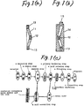
- the present invention can be used in casting various kinds of resin moldings, for example, it can be used in casting an insulating spacer as shown in Fig. 1 (a) which is used to support a GIS connecting conductor.
- reference character 11 designates an epoxy resin molding
- 12 stands for a conductor connecting metal member which is embedded in the central portion of the epoxy resin molding
- 13 points out a bolt insertion hole metal member which is embedded at a given distance on the outer peripheral side of the epoxy resin molding 11.
- a metal mold 14 as shown in Fig. 1 (b), can be used which is split vertically and includes a resin casting port 15 at the top end thereof.
- Fig. 1 (b) there is shown an assembly state of the metal mold 14 in which the conductor connecting metal member 12, bolt insertion hole metal member 13 and the like are assembled together.
- Fig. 1 (c) shows a flow chart when the above-mentioned insulating spacer is manufactured by use of a casting method for forming a resin molding according to the particular embodiment of the invention.
- a material is passed sequentially through a measuring step and a mixing step (a step of mixing the material with a hardener) and is then sent to a casting step.
- a metal mold with the material cast therein is then forwarded to a primary hardening step.
- a mold releasing step in which the metal mold containing the material is separated into the metal mold and a primarily hardened molding.
- a conductor connecting metal member or the like including a bolt insertion hole metal member as well
- the emptied metal mold is re-assembled and is then sent back to the casting step.
- the above-mentioned operations are performed as one circulation or one cycle and, after then, such a circulation flow will be repeated.
- the primarily hardened molding which has been released from the metal mold, is then sent to a secondary hardening step, a finishing step and an inspecting step before it is shipped.
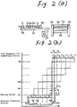
- Fig. 2 (a) shows a manufacturing apparatus which is used in the present invention.
- the apparatus as shown in Fig. 2 (a), comprises devices respectively corresponding to the casting step, primary hardening step, mold releasing step and mold assembling step as well as a device corresponding to the secondary hardening step.
- reference character 2 designates a material casting station which is used to cast a material or a hardener mixed resin into the metal mold.
- 3 stands for a heating line which includes a plurality of heating devices, preferably, heating devices of a sandwich type a 1 , a 2 , --- on the side of a main rail 31 with one end portion thereof situated on the material casting station 2.
- the sandwich type of heating device as shown in Fig. 3, there can be used a structure in which two heating plates 32 each containing an electric heater therein are disposed opposed to each other and are supported by a piston rod 33.
- 34 designates a traverser
- 35 stands for an auxiliary rail which is disposed in the other end portion of the main rail 31, and 4 points out a resin releasing and mold assembling station.
- the flow of one metal mold in the above production line includes a step of moving an assembled and preheated metal mold to the material casting station 2 by use of the traverser 34 and casting the material into the metal mold, a step of moving the material filled metal mold to a predetermined sandwich type heating device by use of the traverser 34 and holding the metal mold by and between the two heating plates 32 for a predetermined period of time to harden the material (this hardening treatment aims at providing the material with such mechanical strength as allows the material to be removed from the metal mold, and this is a so called primary hardening and this primary hardening will be hereinafter referred to as simply hardening), a step of moving the metal mold, in which the hardening of the material is completed (which will be hereinafter referred to as the hardening completed metal mold) to the resin releasing and mold assembling station 4 by use of the traverser 34, and a step of removing the hardened resin/product from the metal mold and then assembling the resin-released metal mold, and other steps.
- Fig. 2 (b) is a time chart which shows the moving states of a metal mold when a resin molding is cast according to the invention by use of the above-mentioned manufacturing apparatus.
- the transverse axis of the flow chart shows an elapsed time.
- the movement line of a metal mold A 1 shows that the material is cast for a given time T 3 in the material casting station.
- the metal mold is sent into a heating device a 1 and is hardened primarily for a given time T 1 , and after this primary hardening, the metal mold is forwarded to the mold releasing and assembling station where the material is removed from the metal mold and the material released metal mold is then assembled again in a given time T 4 .
- the movement lines of metal molds A 2 , --- --- --- A n respectively show the same meaning as that of the metal mold A 1 , except for a time lag t 1 .
- the time T 1 necessary for the primary hardening is much longer than the time T 3 necessary for casting of the material and the time T 4 required for the mold releasing and assembling.
- Fig. 2 (b) the time necessary for the metal mold to reach a given heating device after leaving the material casting station, the time for the metal mold to reach the mold releasing and assembling station from a given heating device, and the time necessary for the metal mold to reach the material casting station from the mold releasing and assembling station are ignored here, because they are very much shorter than the times T 1 , T 3 , T 4 and the like.
- a time lag required to send the metals mold from the heating line to the mold releasing and assembling station is also t 1 in order to balance the metal mold movements with each other.
- the metal mold A 1 stays still in the heating device a 1 and, therefore, another heating device a 2 is necessary which is used to receive the metal mold A 2 sent into the heating line.
- the metal molds A 1 and A 2 stay still in the heating devices a 1 and a 2 respectively and, therefore, it is necessary for another heating device a 3 to be used to receive the metal mold A 3 .
- the metal molds A 1 , --- ---, A n-1 stay still in the heating devices a 1 , --- ---, a n-1 , respectively and, therefore, it is necessary for another heating device a n to receive the metal mold A n that is sent into the heating line.
- the number of metal molds required is n which satisfies an equation, n-1 ⁇ T 1 /t 1 ⁇ n (n is an integer).
- the heating device a 1 completes the primary hardening of the resin contained in the metal mold A 1 , in Fig. 2 (b), as shown by arrows, the metal mold A 1 is forwarded to the mold releasing and assembling station, in which the primarily hardened resin/product is released from the metal mold and the resin released metal mold is then assembled, and the assembled metal mold is further sent to the material casting station in which a new material or resin composition is cast into the metal mold. After that, the metal mold with the material or resin contained therein is again sent into the heating line.
- a time p' (where the metal mold A 1 is put into the heating device a 1 again) is a time which has elapsed during one circulation or one cycle after a time p at which the metal mold A 1 has previously been sent into the heating device a 1 . After this, the cycle will be repeated.
- the preheating treatment can be executed by use of the empty time t.
- the preheating treatment time is expressed as T 2 , then the following condition must be satisfied: t 1 ⁇ T 2 + T 3 + T 4 .
- the metal mold heating time T 1 may be set according to the sizes of the moldings, the hardening properties of the compositions of the resins and the like and, normally, the standard time T 1 may be in the range of 5 to 6 hours.
- the time t 1 is set for 1 hr.
- T 3 is set for 15 min.
- T 4 is set for 30 min., respectively; and, if a preheating treatment is necessary, then the time t 1 is set for 1 hr., T 2 is set for 10 min.
- T 3 is set for 15 min.
- T 4 is set for 30 min., respectively.
- the shortest time that can be set as the time lag t 1 is a longer one than that of the time T 3 necessary for casting of the material and the time T 4 necessary for separating and assembling the metal mold.
- the metal mold A 1 sent again into the heating line is put into the heating device a 1 similarly to the above-mentioned case.
- the above-mentioned time T 1 may vary according to the sizes and shapes of the metal molds, and the hardening properties of the resins.
- the largest number of heating devices may be set according to the longest time T 1 corresponding to the largest kinds and sizes of resin moldings. That is, when casting the relatively smaller kinds and sizes of resin moldings, the required number of heating devices may be selected and used out of the largest number of heating devices.
- a number, T 1 /t 1 , of heating devices each of a sandwich type are used for the number, T 1 /t 1 , of metal molds.
- the manufacturing apparatus used in the invention is not limited to the illustrated one but the number of heating devices of a sandwich type can be set greater than the metal molds to be used so that they can he used as reserves. Also, the heating devices each of a sandwich type can also be arranged on the two sides of the main rail 31.
- the heated state of the resin contained within the metal mold heated by the heating device can be checked by the following mathematical expression 1, where the thermal capacity of the material to be heated is expressed as c, the heat radiation resistance thereof is expressed as r, the quantity of heat generated per unit time by the heating device is expressed as q, and a rise in the temperature of the material to be heated is expressed as ⁇ T:
- the heated state of the resin can be determined by means of the temperature rise velocity v of the material to be heated that can be obtained from the following expression 2:
- the quantity of heat q generated per unit time by the heating device may be made greater (or smaller) (in a conductive heat radiation system, a conduction current is made greater or smaller) to thereby keep constant the temperature rise velocity expressed by the above expression (2), so that the material or resin composition can be hardened primarily while the metal mold heating time T 3 remains the same as the above-mentioned standard time.
- the quantity of heat q generated per unit time by the heating device may be adjusted to thereby control the metal mold heating temperature or heating time T 3 or control both of them, so that the primary hardening condition can be controlled.
- the idle time of the heating device is a time (T 3 + T 4 ) with respect to the time T 1 during which the heating device is used for heating, and a rate of use T 1 /(T 1 + T 3 + T 4 ) is 88% in the case of the above-mentioned standard molding, which means that the heating device can be used with a very high efficiency.
- the idle times of the respective heating devices can be adjusted to thereby change the heating times of the respective metal molds, so that moldings differing in the primary hardening times from each other (moldings respectively differing in the resin composition, size or shape from each other) can also be produced in one flow or in one cycle.
- a vacuum chamber is used to cast the material into the metal mold.
- Such material casting state is shown in Fig. 4.
- the metal mold 14 which is assembled in the above-mentioned manner, is stored within a vacuum chamber 51 from a door provided on the side portion of the vacuum chamber 51, a lower end nozzle 521 of a mixing kiln 52 disposed just above the vacuum chamber 51 is inserted through a nozzle insertion hole 522 formed at the upper end of the vacuum chamber (a seal ring is mounted onto the nozzle insertion hole so that the nozzle can be inserted through the seal ring in a close contact manner) into an casting port 15 of the metal mold 14, the pressure in the vacuum chamber 51 is reduced by means of evacuation (evacuation is started automatically if the metal mold enters the vacuum chamber), and under such reduced pressure a valve 523 of the nozzle 521 is opened to thereby cast the material of the mixing kiln 52 into the metal mold.
- Fig. 2 (a) When the casting of the material into the metal mold is completed, then the evacuation in the vacuum chamber 51 is stopped, the door of the vacuum chamber is opened, in Fig. 2 (a), the material casted metal mold is moved from within the vacuum chamber 51 to the traverser 34, a predetermined sandwich type heating device is selected from a group of sandwich type heating devices a 1 , a 2 , --- in accordance with a control program, the metal mold is moved to and between the two heating plates of the selected sandwich type heating device by computer controlling the traverser 34, and the two heating plates are brought into contact with the metal mold to thereby harden the material primarily.
- a pressurizing hose is connected with the material casting port of the metal mold so that the material can be hardened while pressurizing the upper surface of the casted material with a pressurizing gas such as pressurizing air or the like.
- the metal mold is allowed to escape from the sandwich type heating device, the metal mold is then transferred through the main rail 31 and auxiliary rail 35 to the resin releasing and mold assembling station 4 by means of computer control of the traverser 34, in which station the material or resin is released from the metal mold and the resin-released metal mold is re-assembled again (that is, the conductor connecting metal member and bolt insertion hole metal member are set), the assembled metal mold is then transferred to the traverser, and the metal mold is then moved into the vacuum chamber 51.
- the metal mold which is assembled after the resin/product is released, remains still at sufficiently high temperatures, that is, remains still in the preheated condition and, therefore, normally, such metal mold requires no preheating treatment.
- a preheating treatment is necessary, a predetermined sandwich type heating device is selected out of a plurality of sandwich type heating devices a 1 , a 2 --- in accordance with a control program, the metal mold is transferred to and between the two plates of the selected sandwich type heating device by the computer controlling of the traverser to preheat the metal mold, and the preheated metal mold is moved into the vacuum chamber 51.
- Fig. 2 (a) 53 designates a secondary hardening furnace and 54 stands for a conveyor, respectively. That is, the primarily hardened product released from the metal mold is delivered into the secondary hardening furnace 53, in which the primarily hardened product is hardened secondarily. After completion of the secondary hardening treatment, the secondarily hardened product is finished, for example, burred and is then inspected before it is shipped.
- Fig. 5 (a) a plan view
- Fig. 5 (b) a side view
- FIGs. 5 (a) and (b) designates a turn frame which supports the mixing kiln 52 removably on the arm thereof and then transfers the mixing kiln 52 to a measuring station 61, a stirring station 62, an casting station end 201 and a cleaning station 63 sequentially.
- a mixing resin storage tank into which a predetermined amount of hardenable resin, for example, epoxy resin heated and fused by a resin mixer 65 is supplied by means of a pump (not shown) and also into which a predetermined amount of filler, for example, alumina, silica or the like stored in a filler tank 66 is supplied by means of a pneumatic pipe (not shown) using hot air while heating the filler almost up to the same temperature as the above-mentioned fused resin.
- the mixing resin storage tank 64 keeps on mixing the fused resin and filler together by use of a stirring blade.
- 2 stands for the previously described casting station, there is provided the vacuum chamber 51 in the neighborhood of the above-mentioned casting station end 201, and there is provided a crane 67 between the vacuum chamber 51 and casting station end 201.
- This crane 67 as shown in Fig. 6, includes a suspension wire 672 which suspends a hatch 671.
- the hatch 671 is connected to the mixing kiln 52 situated in the casting station end 201 by means of an electromagnetic chuck or the like, the mixing kiln 52 is lifted by pulling up the suspension line 672, and then a crane carrier 673 is travelled horizontally to thereby transfer the mixing kiln 52 to just above the vacuum chamber 51.
- the resin/filler mixture in the mixing resin storage tank 64 corresponding to a piece of resin molding is measured and is then supplied to the mixing kiln 52.
- the turn frame 6 is rotated 90°, and in the stirring station 62, a predetermined amount of hardener is added from a hardener storage tank 621 to the mixing kiln and is then stirred and mixed together with the resin/filler mixture.
- the turn frame 6 is rotated 90° and, in the casting station end 201, the hatch 671 secured to end portion of the suspension wire of the crane 67 is connected to the mixing kiln 52, the mixing kiln connected to the hatch is lifted up by pulling up the suspension wire, and the crane carrier 673 is travelled horizontally to thereby position the mixing kiln at a position just above the vacuum chamber 51.
- the mixing kiln 52 includes an evacuation opening.
- the evacuation opening is automatically coupled to an evacuation hose (not shown), so that the pressure within the mixing kiln can be reduced.
- the preheat temperature of the metal mold 14 is almost equal to the temperature of the fused resin
- the material stored in the mixing kiln 52 is poured or casted into the metal mold 14.
- the evacuation within the vacuum chamber 51 is stopped, the door of the vacuum chamber 51 is opened and the metal mold 14 is transferred to a predetermined sandwich type heating device for hardening of the material.
- the emptied mixing kiln 52 is returned back to the casting station by travelling the crane carrier horizontally as well as by operating the crane suspension wire, the hatch is removed from the mixing kiln, the mixing kiln is transferred to the cleaning station by rotating the turn frame 90° and the mixing kiln is cleaned there. On completion of such cleaning the mixing kiln is moved to the measuring station. From now on, the measuring of the resin/filler mixture corresponding to a piece of resin molding, mixing of the hardener, casting of the material into the metal mold, and cleaning are executed repeatedly.
- the material casting method there can be made constant the time that extends from addition of the material to the mixing kiln to casting of the resin composition into the metal mold, and there can also be made constant the degree of progress of hardening of the resin composition until the resin composition is cast into the metal mold, so that the hardener mixed resin can be cast into the respective metal molds in the same viscosity state.
- two mixed resin storage tanks 64 may be provided; so that when changing the compositions of the resin, the compositions of the resin to be changed to can be previously mixed in one mixed resin storage tank; and the other mixed resin storage tank, which is currently in use, can be replaced later with said one mixed resin storage tank.
- the primary hardening condition can be controlled according to the present invention, so that moldings differing in the primary hardening times from each other (moldings respectively differing in the resin composition, size or shape from each other) may be produced by computer controlling in one flow or in one cycle.
- the moldings can be produced in one flow or in one cycle by controlling the heating time T 1 of metal mold A 3 . That is, since in the present invention a plurality of metal molds and a plurality of heating devices are used, moldings differing in the primary hardening time from each other can be produced by computer controlling in one flow or in one cycle.
- the heating device the sandwich type of heating device is used.
- the invention is not limited to this, but other kinds of heating devices can also be used.
- the metal mold may be arranged such that it contains an electric heater therein, and a conduction power source for the electric heater may be used in place of the sandwich type of heating device.
- a plurality of metal molds can be circulated at a given time difference corresponding to the number of heating devices provided in the order of a step of casting a hardenable resin composition into a preheating metal mold, a step of heating and hardening the cast material (hardenable resin), and a step of releasing the hardened product/material from the metal mold and then re-assembling metal mold.
- the time that extends from the casting of the material into a mold to the heating of the metal mold sufficient for hardening can be made identical for the respective metal molds and, by casting the hardener mixed resin into the respective metal molds at the same viscosity state, it is possible to eliminate variations in the segregated states of fillers between the metal molds, to completely prevent variations in quality between the products or moldings, and to stabilize the quality of the resin moldings to a high degree.
Landscapes
- Casting Or Compression Moulding Of Plastics Or The Like (AREA)
- Insulators (AREA)
- Insulating Bodies (AREA)
Claims (10)
- Gießverfahren zum Bilden eines Harzformstückes, in dem eine Vielzahl von formgebenden Metallgießformen (14) in einer vorbestimmten Zeitspanne zirkuliert werden, umfassend:einen Schritt, in dem bei einer Gießstation (2) eine aushärtbare Harzzusammensetzung in eine vorgeheizte, formgebende Metallgießform (14) gegossen wird;einen Schritt, in dem das gegossene Harz gehärtet wird, in dem das Führen jeder formgebenden Metallgießform (14) zu einer Heizstation, zum Härten des Harzes in der formgebenden Metallgießform (14), wenn sie mit dem Harz gefüllt worden ist, bewirkt wird;einen Schritt, in dem eine gefüllte Form von der Heizstation zu einer Harzauslösestation (4) bewegt wird, wo die Metallgießformen geleert werden und dann zu der Gießstation zurückgeführt werden;dadurch gekennzeichnet, daßsich bei der Heizstation gefüllte Metallgießformen (a1 bis an) in einer Heizstraße (3) zusammen mit einer Vielzahl von Heizeinrichtungen (32) nacheinander sammeln und sich entlang der Straße auf die Harzauslösestation (4) derart zu bewegen, daß,während eine in dem Härteschritt angewendete Gießform (14) durch eine der Heizeinrichtungen (32) erhitzt wird,eine andere in dem Härteschritt angewendete, formgebende Gießform (14) durch eine andere der Heizeinrichtungen (32) erhitzt wird.
- Gießverfahren zum Bilden eines Harzformstückes nach Anspruch 1, dadurch gekennzeichnet, daß die Vielzahl von Heizeinrichtungen (32) Sandwich-Heizeinrichtungen (32) sind.
- Gießverfahren zum Bilden eines Harzformstückes nach Anspruch 1, dadurch gekennzeichnet, daß ein mit Füller versetzter, mit einem Härter gemischter Harzwerkstoff bei der Gießstation (2) in eine vorgeheizte, formgebende Metallgießform (14) gegossen wird, wobei der gegossene Werkstoff in einem im wesentlichen ausgehärtetem Zustand ist, wenn er bei der Harzauslösestation (4) aus der formgebenden Metallgießform gelöst wird; das ausgelöste Harz-Gießprodukt dann einem zweiten Härteschritt unterworfen wird; und die Vielzahl von Heizeinrichtungen (32) an der Seite der Heizstraße (3) angeordnet ist.
- Gießverfahren zum Bilden eines Harzformstückes nach Anspruch 1, dadurch gekennzeichnet, daß die formgebende Metallgießform (14) während aller Schritte in einer vertikalen Richtung gestützt wird.
- Gießverfahren zum Bilden eines Harzformstückes nach Anspruch 2, dadurch gekennzeichnet, daß die formgebende Metallgießform (14) während aller Schritte in einer vertikalen Richtung gestützt wird.
- Gießverfahren zum Bilden eines Harzformstückes nach Anspruch 3, dadurch gekennzeichnet, daß die formgebende Metallgießform (14) während aller Schritte in einer vertikalen Richtung gestützt wird.
- Gießverfahren zum Bilden eines Harzformstückes nach Anspruch 1, dadurch gekennzeichnet, daß die sich von der Vervollständigung des Gießens des aushärtbaren Harzes bis zum Erhitzen der Metallgießform zum Härten erstreckende Zeit für alle der Metallgießformen einheitlich gemacht wird.
- Gießverfahren zum Bilden eines Harzformstückes nach Anspruch 2, dadurch gekennzeichnet, daß die sich von der Vervollständigung des Gießens des aushärtbaren Harzes bis zum Erhitzen der Metallgießform zum Härten erstreckende Zeit für alle der Metallgießformen einheitlich gemacht wird.
- Gießverfahren zum Bilden eines Harzformstückes nach Anspruch 3, dadurch gekennzeichnet, daß die sich von der Vervollständigung des Gießens des aushärtbaren Harzes bis zum Erhitzen der Metallgießform zum Härten erstreckende Zeit für alle der Metallgießformen einheitlich gemacht wird.
- Gießverfahren zum Bilden eines Harzformstückes nach Anspruch 1, weiterhin Schritte zum Bereitstellen des aushärtbaren Harzes umfassend, das folgende Schritte umfaßt:das Vorsehen eines Drehrahmens (6), drehbar durch eine Meßstation (61) beweglich, einer Rührstation (62) für den Härter, einer Werkstoffgießstation (201) und einer Reinigungsstation (63), nacheinander in dieser Reihenfolge; unddas Vorsehen eines durch den Drehrahmen (6) entfernbar gestützten Gefäßes (52),wobei die Meßstation (61) eine Einrichtung zum Messen und Gießen eines Hauptwerkstoffes in das Gefäß (52) umfaßt,
der aus einer Mischung von einem Harz und einem Füller besteht;
wobei die Rührstation (62) für den Härter eine Einrichtung zum Gießen einer vorbestimmten Menge von Härter in das Gießgefäß (52) für den Hauptwerkstoff und das Mischen des Hauptwerkstoffes mit dem Härter umfaßt, um das aushärtbare Harz zu bilden, und
wobei die Werkstoffgießstation (2) eine Einrichtung (67) zum Entfernen des Gefäßes (52), das darin das aushärtbare Harz enthält, von dem Drehrahmen (6), das Gießen des in dem entfernten Gefäß (52) enthaltenen, aushärtbaren Harzes in eine formgebende Metallgießform (14), und, nach Vervollständigung des Gießens, das Zurückführen des Gefäßes (52) zu dem Drehrahmen (6) umfaßt, so daß das Gefäß durch den Drehrahmen gestützt werden kann.
Applications Claiming Priority (6)
| Application Number | Priority Date | Filing Date | Title |
|---|---|---|---|
| JP9381192 | 1992-03-19 | ||
| JP93811/92 | 1992-03-19 | ||
| JP335391/92 | 1992-11-21 | ||
| JP33539192 | 1992-11-21 | ||
| JP5063205A JPH06208812A (ja) | 1992-03-19 | 1993-02-26 | 樹脂成形体の注型方法 |
| JP63205/93 | 1993-02-26 |
Publications (3)
| Publication Number | Publication Date |
|---|---|
| EP0561414A2 EP0561414A2 (de) | 1993-09-22 |
| EP0561414A3 EP0561414A3 (en) | 1993-11-18 |
| EP0561414B1 true EP0561414B1 (de) | 1997-06-04 |
Family
ID=27298082
Family Applications (1)
| Application Number | Title | Priority Date | Filing Date |
|---|---|---|---|
| EP93104518A Expired - Lifetime EP0561414B1 (de) | 1992-03-19 | 1993-03-19 | Giessverfahren zur Herstellung von Formteilen aus Kunststoff |
Country Status (4)
| Country | Link |
|---|---|
| US (1) | US5746953A (de) |
| EP (1) | EP0561414B1 (de) |
| JP (1) | JPH06208812A (de) |
| DE (1) | DE69311172D1 (de) |
Families Citing this family (4)
| Publication number | Priority date | Publication date | Assignee | Title |
|---|---|---|---|---|
| US6854173B2 (en) * | 2002-07-08 | 2005-02-15 | The Boeing Company | Fastener installation apparatus and associated method |
| CN102873805B (zh) * | 2012-10-11 | 2014-07-09 | 济南大学 | 一种轻质节能墙板成型生产线的集群控制系统 |
| CN104914829B (zh) * | 2015-05-07 | 2018-07-20 | 北京星航机电装备有限公司 | 一种混凝土预制板生产线自动监控系统及其监控方法 |
| CN108394055A (zh) * | 2018-03-13 | 2018-08-14 | 成都时代立夫科技有限公司 | 一种树脂浇注机浇注组分比例的准实时检测装置和方法 |
Citations (1)
| Publication number | Priority date | Publication date | Assignee | Title |
|---|---|---|---|---|
| FR2573338A1 (fr) * | 1984-11-16 | 1986-05-23 | Etu Tech Servi Informatiq Bure | Machine du type carrousel pour preparation de melanges, specialement de mortiers |
Family Cites Families (8)
| Publication number | Priority date | Publication date | Assignee | Title |
|---|---|---|---|---|
| US1693264A (en) * | 1926-12-03 | 1928-11-27 | Goodrich Co B F | Method of vulcanizing successive separate articles and apparatus therefor |
| US3619447A (en) * | 1970-01-21 | 1971-11-09 | Westinghouse Electric Corp | Casting methods for encapsulating electrical conductors |
| FR2088002A1 (en) * | 1970-05-05 | 1972-01-07 | Kleber Colombes | Continuous vulcanisation - by heating and pressing stacked moulds between press plates |
| US4575328A (en) * | 1984-03-06 | 1986-03-11 | Asm Fico Tooling, B.V. | Automatic continuously cycleable molding apparatus |
| US4957671A (en) * | 1985-06-11 | 1990-09-18 | M. A. Industries, Inc. | Manufacture of plastic products |
| US4961888A (en) * | 1988-07-28 | 1990-10-09 | Liquid Molding Systems, Inc. | Liquid silicone molding process |
| JPH0390319A (ja) * | 1989-09-01 | 1991-04-16 | Sogo Shika Iryo Kenkyusho:Kk | 可視光重合型レジンの連続硬化方法及び装置 |
| JPH0698628B2 (ja) * | 1989-09-01 | 1994-12-07 | 株式会社総合歯科医療研究所 | 可視光重合型レジンの連続硬化方法及び装置 |
-
1993
- 1993-02-26 JP JP5063205A patent/JPH06208812A/ja active Pending
- 1993-03-19 DE DE69311172T patent/DE69311172D1/de not_active Expired - Lifetime
- 1993-03-19 EP EP93104518A patent/EP0561414B1/de not_active Expired - Lifetime
-
1995
- 1995-04-06 US US08/418,129 patent/US5746953A/en not_active Expired - Fee Related
Patent Citations (1)
| Publication number | Priority date | Publication date | Assignee | Title |
|---|---|---|---|---|
| FR2573338A1 (fr) * | 1984-11-16 | 1986-05-23 | Etu Tech Servi Informatiq Bure | Machine du type carrousel pour preparation de melanges, specialement de mortiers |
Also Published As
| Publication number | Publication date |
|---|---|
| EP0561414A2 (de) | 1993-09-22 |
| EP0561414A3 (en) | 1993-11-18 |
| JPH06208812A (ja) | 1994-07-26 |
| US5746953A (en) | 1998-05-05 |
| DE69311172D1 (de) | 1997-07-10 |
Similar Documents
| Publication | Publication Date | Title |
|---|---|---|
| US5865237A (en) | Method of producing molded bodies of a metal foam | |
| CN102019348B (zh) | 一种低压导向联体空心叶片的制备方法 | |
| JP2508696B2 (ja) | スラッシュ成形装置 | |
| JP2754275B2 (ja) | 繊維成形体及びその製造方法 | |
| US5746953A (en) | Casting method for forming a resin molding | |
| US4108931A (en) | System of making molds for investment casting | |
| IL91734A0 (en) | Method for forming metal matrix composite bodies with a dispersion casting technique and products produced thereby | |
| US10850320B2 (en) | Apparatus for low-pressure casting | |
| US6635197B2 (en) | Method and apparatus for casting molten materials using phase-change material | |
| JPS6241099B2 (de) | ||
| CN1123529A (zh) | 将熔融金属、特别是铸铁供给到铸造机的装置以及装有这种供给装置的铸造设备 | |
| CN112877584B (zh) | 一种金属基复合陶瓷钢的生产装置及生产方法 | |
| GB2050220A (en) | Method and installation for low pressure casting of metal parts in a thin-walled sand impression | |
| JP2023545427A (ja) | 耐火性注ぎ口 | |
| JP2001030213A (ja) | 硫黄組成物成形品の製造方法 | |
| DE4401475C1 (de) | Verfahren und Vakuumkammer zur Herstellung von Metallmodellen | |
| US2716791A (en) | Investment casting | |
| CN216099510U (zh) | 制备陶瓷雾化芯的热压铸设备 | |
| US2429145A (en) | Mold for casting metals | |
| CN114603084A (zh) | 一种精密熔模铸造设备及其熔模铸造方法 | |
| KR101528322B1 (ko) | 유황 고화체의 제조 방법 및 유황 고화체의 제조 장치 | |
| JPH05325694A (ja) | 樹脂絶縁体の製造方法 | |
| EP0815986A1 (de) | Vorrichtung und Verfahren zum Extrudieren von Formsand und Gaszuführ | |
| JPH05266745A (ja) | 樹脂成形体の注型方法 | |
| JPH0691661A (ja) | 熱硬化性樹脂成形方式 |
Legal Events
| Date | Code | Title | Description |
|---|---|---|---|
| PUAI | Public reference made under article 153(3) epc to a published international application that has entered the european phase |
Free format text: ORIGINAL CODE: 0009012 |
|
| AK | Designated contracting states |
Kind code of ref document: A2 Designated state(s): BE CH DE FR GB IT LI |
|
| PUAL | Search report despatched |
Free format text: ORIGINAL CODE: 0009013 |
|
| AK | Designated contracting states |
Kind code of ref document: A3 Designated state(s): BE CH DE FR GB IT LI |
|
| 17P | Request for examination filed |
Effective date: 19940203 |
|
| 17Q | First examination report despatched |
Effective date: 19950220 |
|
| GRAG | Despatch of communication of intention to grant |
Free format text: ORIGINAL CODE: EPIDOS AGRA |
|
| GRAH | Despatch of communication of intention to grant a patent |
Free format text: ORIGINAL CODE: EPIDOS IGRA |
|
| GRAH | Despatch of communication of intention to grant a patent |
Free format text: ORIGINAL CODE: EPIDOS IGRA |
|
| GRAA | (expected) grant |
Free format text: ORIGINAL CODE: 0009210 |
|
| AK | Designated contracting states |
Kind code of ref document: B1 Designated state(s): BE CH DE FR GB IT LI |
|
| PG25 | Lapsed in a contracting state [announced via postgrant information from national office to epo] |
Ref country code: LI Effective date: 19970604 Ref country code: IT Free format text: LAPSE BECAUSE OF FAILURE TO SUBMIT A TRANSLATION OF THE DESCRIPTION OR TO PAY THE FEE WITHIN THE PRE;WARNING: LAPSES OF ITALIAN PATENTS WITH EFFECTIVE DATE BEFORE 2007 MAY HAVE OCCURRED AT ANY TIME BEFORE 2007. THE CORRECT EFFECTIVE DATE MAY BE DIFFERENT FROM THE ONE RECORDED.SCRIBED TIME-LIMIT Effective date: 19970604 Ref country code: FR Effective date: 19970604 Ref country code: CH Effective date: 19970604 |
|
| REG | Reference to a national code |
Ref country code: CH Ref legal event code: EP |
|
| REF | Corresponds to: |
Ref document number: 69311172 Country of ref document: DE Date of ref document: 19970710 |
|
| PG25 | Lapsed in a contracting state [announced via postgrant information from national office to epo] |
Ref country code: DE Effective date: 19970905 |
|
| EN | Fr: translation not filed | ||
| REG | Reference to a national code |
Ref country code: CH Ref legal event code: PL |
|
| PG25 | Lapsed in a contracting state [announced via postgrant information from national office to epo] |
Ref country code: GB Free format text: LAPSE BECAUSE OF NON-PAYMENT OF DUE FEES Effective date: 19980319 |
|
| PLBE | No opposition filed within time limit |
Free format text: ORIGINAL CODE: 0009261 |
|
| PGFP | Annual fee paid to national office [announced via postgrant information from national office to epo] |
Ref country code: BE Payment date: 19980518 Year of fee payment: 6 |
|
| 26N | No opposition filed | ||
| GBPC | Gb: european patent ceased through non-payment of renewal fee |
Effective date: 19980319 |
|
| PG25 | Lapsed in a contracting state [announced via postgrant information from national office to epo] |
Ref country code: BE Free format text: LAPSE BECAUSE OF NON-PAYMENT OF DUE FEES Effective date: 19990331 |
|
| BERE | Be: lapsed |
Owner name: NITTO DENKO CORP. Effective date: 19990331 |