EP0561561A2 - Traitement de signal vidéo numérique - Google Patents
Traitement de signal vidéo numérique Download PDFInfo
- Publication number
- EP0561561A2 EP0561561A2 EP19930301828 EP93301828A EP0561561A2 EP 0561561 A2 EP0561561 A2 EP 0561561A2 EP 19930301828 EP19930301828 EP 19930301828 EP 93301828 A EP93301828 A EP 93301828A EP 0561561 A2 EP0561561 A2 EP 0561561A2
- Authority
- EP
- European Patent Office
- Prior art keywords
- frames
- picture
- input
- acquisition
- frame
- Prior art date
- Legal status (The legal status is an assumption and is not a legal conclusion. Google has not performed a legal analysis and makes no representation as to the accuracy of the status listed.)
- Granted
Links
- 238000012545 processing Methods 0.000 title claims abstract description 31
- 238000000034 method Methods 0.000 claims abstract description 45
- 230000033001 locomotion Effects 0.000 claims description 142
- 239000013598 vector Substances 0.000 claims description 60
- 230000002123 temporal effect Effects 0.000 claims description 53
- 230000000750 progressive effect Effects 0.000 claims description 49
- 238000006243 chemical reaction Methods 0.000 claims description 15
- 230000008569 process Effects 0.000 claims description 8
- 239000000463 material Substances 0.000 description 9
- 239000002131 composite material Substances 0.000 description 7
- 238000010586 diagram Methods 0.000 description 5
- 230000003044 adaptive effect Effects 0.000 description 4
- 239000003638 chemical reducing agent Substances 0.000 description 3
- 230000001419 dependent effect Effects 0.000 description 3
- 238000003384 imaging method Methods 0.000 description 3
- 238000012986 modification Methods 0.000 description 3
- 230000004048 modification Effects 0.000 description 3
- 238000005070 sampling Methods 0.000 description 3
- 230000008859 change Effects 0.000 description 2
- 230000003068 static effect Effects 0.000 description 2
- 238000012360 testing method Methods 0.000 description 2
- 238000012935 Averaging Methods 0.000 description 1
- XUIMIQQOPSSXEZ-UHFFFAOYSA-N Silicon Chemical compound [Si] XUIMIQQOPSSXEZ-UHFFFAOYSA-N 0.000 description 1
- 230000009471 action Effects 0.000 description 1
- 230000002411 adverse Effects 0.000 description 1
- 230000000295 complement effect Effects 0.000 description 1
- 230000003111 delayed effect Effects 0.000 description 1
- 238000011161 development Methods 0.000 description 1
- 230000018109 developmental process Effects 0.000 description 1
- 238000010894 electron beam technology Methods 0.000 description 1
- 238000009499 grossing Methods 0.000 description 1
- 238000013507 mapping Methods 0.000 description 1
- 230000004044 response Effects 0.000 description 1
- 229910052710 silicon Inorganic materials 0.000 description 1
- 239000010703 silicon Substances 0.000 description 1
Images






Classifications
-
- H—ELECTRICITY
- H04—ELECTRIC COMMUNICATION TECHNIQUE
- H04N—PICTORIAL COMMUNICATION, e.g. TELEVISION
- H04N7/00—Television systems
- H04N7/01—Conversion of standards, e.g. involving analogue television standards or digital television standards processed at pixel level
- H04N7/0135—Conversion of standards, e.g. involving analogue television standards or digital television standards processed at pixel level involving interpolation processes
- H04N7/014—Conversion of standards, e.g. involving analogue television standards or digital television standards processed at pixel level involving interpolation processes involving the use of motion vectors
-
- H—ELECTRICITY
- H04—ELECTRIC COMMUNICATION TECHNIQUE
- H04N—PICTORIAL COMMUNICATION, e.g. TELEVISION
- H04N5/00—Details of television systems
- H04N5/14—Picture signal circuitry for video frequency region
- H04N5/144—Movement detection
- H04N5/145—Movement estimation
Definitions
- This invention relates to digital video signal processing and in particular with processing an input digital video signal representing a series of input frames to produce an output digital video signal representing a series of output frames.
- the invention is more particularly concerned with the case where at least some of the input frames each have a first picture portion acquired with a first acquisition characteristic (such as, for example, 60 fields/second, 2:1 interlace) and a second picture portion acquired with a second acquisition characteristic (such as, for example, 30 frames/second, 1:1 progressive scan).
- a first acquisition characteristic such as, for example, 60 fields/second, 2:1 interlace
- a second picture portion acquired with a second acquisition characteristic (such as, for example, 30 frames/second, 1:1 progressive scan).
- This invention is more particularly, but not exclusively, concerned with the case where the output signal simulates frames acquired with a different acquisition characteristic (such as, for example, 24 frames/second, 1:1 progressive scan), but is also applicable in the case where the output signal is to simulate frames wholly acquired with the acquisition characteristic of one of the picture portions of the input signal (such as, for example, 60 fields/second, 2:1 interlace).
- a different acquisition characteristic such as, for example, 24 frames/second, 1:1 progressive scan
- the output signal is to simulate frames wholly acquired with the acquisition characteristic of one of the picture portions of the input signal (such as, for example, 60 fields/second, 2:1 interlace).
- Patent Application GB 2231228 A describes a method of converting a digital video signal in 60 fields/second, 2:1 interlace, format so as to simulate acquisition at 24 frames/second, 1:1 progressive scan format.
- progressive scan format frames are produced temporally aligned with the first, third, fourth, sixth, eighth and ninth of the ten input fields each either by inter-field interpolation of the respective input field with the preceding and succeeding fields, and/or by intra-field interpolation of the respective input field, depending upon the amount of motion detected in the input picture.
- the first and fourth progressive scan converted frames can be directly used as the first and third output frames.
- the second and fourth output frames are produced by motion compensated temporal interpolation half-way between the second and third progressive scan converted frames, and half-way between the fifth and sixth progressive scan converted frames, respectively.
- Motion compensated temporal interpolation involves producing, for each pixel in the output frame, a motion vector indicative of the motion of the object which that pixel represents between the respective pair of progressive scan converted frames.
- the value of each pixel in the output frame is then determined by averaging the values of the pixels located at positions in the respective pair of progressive scan converted frames offset by one-half of the motion vector one way and the other, respectively, from the position of the pixel in the output frame.
- Patent Application GB 2249907 A describes a number of developments to the method described in GB 2231228 A, for example for converting 30 frames/second, 1:1 progressive scan format material by motion compensated temporal interpolation so as to simulate acquisition at 24 frames/second, 1:1 progressive scan format.
- an input video signal which is a composite of material acquired with a 60 fields/second, 2:1 interlace, video camera and material acquired from a computer graphics system in 30 frames/second, 1:1 progressive scan format (but included in the 60 fields/second, 2:1 interlace, signal with the fields of each pair temporally co-sited) to produce an output video signal which simulates acquisition at 24 frames/second, 1:1 progressive scan format, so that the output signal can be used, for example, with an electron beam recorder to produce a 24 frames/second film.
- This example involves a change of frame rate.
- a first aspect of the present invention is more particularly concerned with providing a method of processing an input digital video signal representing a series of input frames to produce an output video signal representing a series of output frames, at least some of the input frames each having a first picture portion having a first acquisition characteristic and a second picture portion having a second acquisition characteristic.
- the method of this first aspect of the present invention is characterised by the steps of distinguishing between the first and second picture portions in the input frames; and processing the first and second picture portions differently to produce the output frames so that the output frames simulate acquisition of the first and second picture portions with generally the same acquisition characteristic.
- the distinguishing step may comprise detecting picture motion between fields of the same input frame; and the processing step may comprise producing an output frame: generally by intra-field interpolation of a respective input field in areas of relatively large detected motion; and generally by combination of respective input fields in areas of no or relatively small detected motion.
- the processing step preferably includes combining, for each pixel, the corresponding intra-field interpolated pixel value with the corresponding field-combined pixel value in proportion to a degree of detected motion of that pixel.
- this example of the method may further comprise the step of further processing the output frames using motion compensated temporal interpolation to simulate acquisition with a different acquisition characteristic (e.g. 24Hz, 1:1).
- first example of the invention involves decimation of the temporal sampling rate, and thus there is a loss of picture data.
- the second picture portions are acquired as pairs of interlaced fields at the first frame rate (e.g.
- the distinguishing step may include forming a first series of difference frames corresponding to the difference between the fields of each input frame; and the processing step may include: forming a series of progressive scan picture frames at least by intra-field interpolation of one field of each frame so that the interpolated picture frames are temporally co-sited with the first picture portions of respective ones of the input frames; producing a second series of difference frames by motion compensated temporal interpolation of the first series of difference frames so that the second difference frames are temporally co-sited with respect to the first picture portions of respective ones of the input frames; and matting the input frames and the interpolated picture frames using the second difference frames as a key signal.
- the distinguishing step may include forming a first series of difference frames corresponding to the difference between the fields of each input frame; and the processing step comprises the steps of: forming a first series of intermediate frames by a motion compensated temporal interpolation process for converting the first picture areas to simulate acquisition with the third acquisition characteristic; forming a second series of intermediate frames by a motion compensated temporal interpolation process for converting the second picture areas to simulate acquisition with the third acquisition characteristic, each second intermediate frame being temporally co-sited with a respective one of the first intermediate frames; forming a second series of difference frames by motion compensated temporal interpolation for converting the first difference frames to the third acquisition characteristic, each second difference frame being temporally co-sited with a respective one of the first intermediate frames; and matting the first and second intermediate frames using the second difference frames as a key signal.
- the processing step comprises the steps of: forming a first series of intermediate frames by a motion compensated temporal interpolation process for converting the first picture areas to simulate acquisition with the third acquisition characteristic
- This second example of the invention and the modification thereto involve the generation of difference frames from the source video.
- the source video may have been post-produced using a key signal, and in a third example of the invention this key signal is utilised in the acquisition conversion process.
- this key signal is utilised in the acquisition conversion process. More specifically, in the third example of the method of the invention in which the first picture portions are acquired as progressive scan frames at a first frame rate (e.g. 30Hz, 1:1), the second picture portions are acquired as pairs of interlaced fields at the first frame rate (e.g. 60Hz, 2:1), the input signal is accompanied by a series of key frames indicating the first and second picture portions, and the output video signal simulates acquisition with a third different acquisition characteristic (e.g.
- the distinguishing step may comprise detecting the key frames; and the processing step may include: forming a first series of intermediate frames by motion compensated temporal interpolation for converting the first picture areas to simulate acquisition with the third acquisition characteristic; forming a second series of intermediate frames by motion compensated temporal interpolation for converting the second picture areas to simulate acquisition with the third acquisition characteristic, each second intermediate frame being temporally co-sited with a respective one of the first intermediate frames; forming a second series of key frames by motion compensated temporal interpolation for converting the detected key frames to the third acquisition characteristic, each second key frame being temporally co-sited with a respective one of the first intermediate frames; and matting the first and second intermediate frames using the second key frames as a key signal.
- the processing step includes: processing the input frames to simulate a first conversion from the first acquisition characteristic to the output acquisition characteristic using motion compensated temporal interpolation in which motion vectors are developed for pixels in the picture (for example as described in patent application GB 2231228 A or GB 2249907 A); and developing a measure of merit for each motion vector; and the distinguishing step is performed in dependence upon the measures of merit.
- the processing step may further include: processing the input frames to simulate a second conversion from the second acquisition characteristic to the output acquisition characteristic using motion compensated temporal interpolation in which motion vectors are developed for pixels in the picture; and developing a measure of merit for each motion vector; and the distinguishing step may be performed in dependence upon a comparison of the measures of merit of the first and second conversions. The distinguishing step may also be performed in dependence upon a comparison of the motion vectors of the first and second conversions.
- the present invention also provides apparatus adapted to perform the methods described above.
- FIG. 1 shows frames having only nine active lines, and it should be noted that actual high-definition video has of the order of one thousand active lines.
- the temporal sampling rate of the input signal is decimated to the lowest common denominator of the acquisition rates of the two portions of the input signal, that is 30Hz, 1:1 in this example.
- the first row A of Figure 1 shows a series of the input fields at 60Hz, 2:1, representing a square towards the top of the picture moving to the left, a rectangle towards the bottom of the picture moving to the right, and a static background.
- the portion of the picture to the left of the dotted line (and thus including the rectangle) was acquired at 30Hz 1:1 whereas the portion of the picture to the right of the dotted line (and thus including the square) was acquired at 60Hz, 2:1.
- 1:1 field pairs could be directly combined, as shown in row B of Figure 1. If this were done, the background and 30Hz, 1:1 acquired rectangle would be properly represented in the combined 30Hz, 1:1 picture.
- the 60Hz, 2:1, acquired rectangle would suffer from interlace smear, as shown in row B of Figure 1.
- the picture is formed by intra-field interpolation of one of the fields of the pair.
- the picture is formed by a combination of intra-field interpolation of one of the fields of the pair and a combination of the two fields of the pair.
- no motion is detected, the whole of the combined frame is produced by combination of the two fields of the pair. Assuming that the square of Figure 1 has a large degree of motion, then this process will produce output frames as shown in row C of Figure 1, which are a better 30Hz 1:1 representation of the picture than the frames of row B of Figure 1.
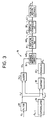
- Input fields if n on line 10 are supplied to a field store 12, an intra-field interpolator 14, a motion detector 16 and a field combiner 18.
- the field store 12 produces a delay so that the fields if n-1 output therefrom on line 20 are one field period behind the input fields if n .
- the delayed fields if n-1 are also supplied to the motion detector 16 and the field combiner.
- Intra-field interpolated frames are supplied by the interpolator 14 to a proportional combiner 22, and field combined frames are supplied by the field combiner 18 to the proportional combiner 22.
- the motion detector 16 For each pixel in a frame to be output, the motion detector 16 produces a motion estimate value P n ranging from, say, 0 to 255 indicative of the detected motion of the object which that pixel represents, and the proportional combiner 22 combines the values of the corresponding pixels produced by the intra-field interpolator 14 and the field combiner 18 in accordance with the value of the motion estimate value P n to produce the output pixel value, which is supplied to an output buffer 24, which then produces output frames 0F n/2 simulating acquisition at 30Hz, 1:1.
- the intra-field interpolator 14 produces a vertically interpolated frame IF n/2 from every other input field if2, if4, if6, «
- the value of a pixel at location (x,y) in the interpolated frame IF n/2 is equal to the value of the pixel at the same location (x,y) in the corresponding even input field if n .
- the value of a pixel at location (x,y) in the interpolated frame IF n/2 is the average of the values of the pixels at the locations (x,y-1) and (x,y+1) above and below that location in the corresponding even input field if n .
- the proportional combiner 22 produces the value 0P n/2 (x,y) of each pixel of the output frame 0F n/2 by adding the proportion P n (x,y) of the value IF n/2 (x,y) of the corresponding pixel of the intra-field interpolated frame with the complementary proportion 256-P n (x,y) of the value CF n/2 (x,y) of the field combined frame. That is to say:
- the motion detector 16 will now be described in further detail with reference to Figure 3.
- the operation of the motion detector is in some ways similar to the operation of the corresponding apparatus described in detail with reference to Figures 8 to 14 of patent application GB 2231228 A.
- the inter-field difference signal of two fields of the same frame is used to indicate motion, rather than the difference signal between the two fields to either side of the field under consideration, as in the case of GB 2231228 A.
- an interpolator 26 is used on the odd field if n-1 to produce an interpolated even polarity field if n-1 ', and a filter 28 is used on the even input field if n to match the response of the interpolator 26 and produce a filtered even polarity field if n '.
- the spatial intra-field filter 40 may be arranged to filter more extensively vertically and also to filter horizontally in order to produce more smoothing of the difference values.
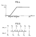
- the difference frame DF n is applied to a non-linear mapping function 42 which has a characteristic as shown in Figure 4, so that: for a difference value DF n (x,y) from zero to a breakpoint 1 the motion estimate value P n (x,y) is zero; for a difference value DF n (x,y) greater than a breakpoint 2 the motion estimate value P n (x,y) is the maximum, say 255; and for difference values DF n (x,y) between breakpoint 1 and breakpoint 2, the motion estimate value P n (x,y) increases progressively.
- the first output frame 0F1 may be directly derived from the first input frame IF1.
- the second output frame 0F2 is temporally interpolated with motion compensation one quarter of the way between the second and third input frames IF2, IF3;
- the third output frame 0F3 is temporally interpolated with motion compensation half-way between the third and fourth input frames IF3, IF4;
- the fourth output frame 0F4 is temporally interpolated with motion compensation three-quarters of the way between the fourth and fifth input frames IF4, IF5.
- the process repeats for the next five input frames IF6 to IF10 and the next four output frames 0F5 to 0F8, and so on.
- motion compensated temporal interpolation it is meant that for each pixel in the output frame, a motion vector is generated indicative of the motion of the object which that pixel represents between the corresponding two input frames to be interpolated.
- the value of the output pixel is then derived from the values of the pixels in the two input frames offset from the location of the output pixel by amounts dependent on the motion vector and the temporal interpolation ratio.
- the output pixel value 0F2(x,y) at location (x,y) is given by: where M2(x,y) is the motion vector for a pixel at location (x,y) in output frame 0F2, and IF2 ⁇ ⁇ and IF3 ⁇ ⁇ are the pixel values at the appropriate locations in input frames IF2, IF3.
- row A represents a series of six frames A1 to A6 or twelve fields a1 to a12 of 60Hz, 2:1 interlace material.
- 60Hz, 2:1 interlace some parts of the picture were acquired using a 60Hz, 2:1 interlace video camera and thus the two fields of each frame are temporally offset, whereas other parts of the picture were acquired by 30Hz, 1:1 computer graphics, and thus in these parts the two fields of each frame are temporally aligned.
- the input fields a1 to a12 are vertically interpolated to produce a series of twelve full frames B1 to B12 as represented by row B, and each pair of vertically interpolated frames derived from the same input frame are subtracted to produce a series of six difference frames C1 to C6, as represented by row C.
- the difference frames may be produced by simple subtraction, but more preferably the difference values are also normalised by an arrangement similar to elements 30 to 36 described above with reference to Figure 3.
- the six difference frames are then 30Hz, 1:1 to 24Hz, 1:1 converted using motion compensated temporal interpolation to produce a series of four key frames D1 to D4, as represented by row D.
- the first key frame D1 is interpolated three-quarters of the way between the first and second difference frames C1, C2; the second key frame D2 is directly derived from the third difference frame C3; the third key frame D3 is interpolated one-quarter of the way between the fourth and fifth difference frames C4, C5; and the fourth key frame D4 is interpolated half-way between the fifth and sixth difference frames C5, C6.
- Row E of Figure 6 also shows the six input frames A1 to A6/twelve input fields a1 to a12.
- the two fields of each frame are directly combined to produce a series of six full frames F1 to F6 as represented by row F.
- the 30Hz, 1:1 full frames are then 30Hz, 1:1 to 24Hz, 1:1 converted using motion compensated temporal interpolation to produce a series of four 30Hz, 1:1 to 24Hz, 1:1 converted frames G1 to G4 as represented by row G.
- the first converted frame G1 is produced directly from the second 30Hz frame F2.
- the second converted frame G2 is interpolated one-quarter of the way between the third and fourth 30Hz frames F3, F4.
- the third converted frame G3 is interpolated half-way between the fourth and fifth 30Hz frames F4, F5.
- the fourth converted frame G4 is interpolated three-quarters of the way between the fifth and sixth 30Hz frames F5, F6.
- Row H of Figure 6 also shows the six input frames A1 to A6/twelve input fields a1 to a12.
- certain of the fields are progressive scan converted using motion adaptive intra-field and inter-field interpolation (as described in detail in patent application GB 2231228 A) to produce a series of six full frames I1 to I6, as represented by row I.
- the first to sixth progressive scan converted frames I1 to I6 are produced from the third, fifth, sixth, eighth, tenth and eleventh input fields a3, a5, a6, a8, a10, a11, respectively, and optionally from the fields immediately preceding and succeeding those fields.
- the six progressive scan converted frames I1 to I6 are then converted using motion compensated temporal interpolation to produce a series of four 60Hz, 2:1, to 24Hz, 1:1 converted frames J1 to J4, as represented by row J.
- the first and third 24Hz, 1:1 frames J1, J3 are directly produced from the first and fourth progressive scan converted frames I1, I4.
- the second and fourth 24Hz, 1:1 frames J2, J4 are produced by motion compensated temporal interpolation half-way between the second and third progressive scan converted frames I2, I3, and half-way between the fifth and sixth progressive scan converted frames I5, I6, respectively.
- the four key frames D1 to D4 of row D are temporally aligned with respective ones of the four 30Hz, 1:1 to 24Hz, 1:1 converted frames G1 to G4 of row G and are also temporally aligned with respective ones of the four 60Hz, 2:1 to 24Hz, 1:1 converted frames J1 to J4 of row J.
- the output picture signal is produced by selecting either the 30Hz, 1:1 to 24Hz, 1:1 converted signal (row G) or the 60Hz, 2:1 to 24Hz, 1:1 converted signal (row J) in dependence upon the value, for the pixel under consideration, of the 24Hz, 1:1 key signal (row D). Specifically, if the key signal is less than a predetermined threshold, the corresponding pixel value of the 30Hz, 1:1 to 24Hz, 1:1 signal is selected, whereas if the key signal for that pixel is greater than the threshold, the corresponding pixel value of the 60Hz, 2:1 to 24Hz, 1:1 signal is selected.
- FIG. 7 An example of how the above-described arrangement may operate is shown in Figure 7.
- Row A of Figure 7 shows five fields a3 to a7 of the input 60Hz, 2:1 video signal.
- a circular object acquired at 60Hz, 2:1 is moving to the left, whereas towards the bottom of the picture a rectangular object acquired at 30Hz, 1:1 is moving to the right.
- the background is static. (For simplicity, Figure 7 does not attempt to distinguish between the odd and even lines of a frame.) Because the circular object was acquired at 60Hz, 2:1, its position appears to move progressively over the five fields a3 to a7 of row A of Figure 7.
- Row C of Figure 7 shows the three corresponding difference frames C2 to C4.
- the only movement between the two fields of a frame is that of the moving circular object, and the difference frames contain the portions of the circular object which are covered or uncovered between fields of a pair.
- Row D of Figure 7 shows the corresponding key signal frames D1, D2.
- Row J of Figure 7 shows the two corresponding 60Hz, 2:1 to 24Hz, 1:1 converted frames J1, J2.
- the circular object In the second of these two frames J2, the circular object is correctly located, temporally interpolated between its locations in the third and fourth fields a5, a6 of row A.
- the rectangular object is in the wrong position, because its position should have been interpolated between the second and third frames A3, A4 of row A, rather than being derived primarily from its position in the third and fourth fields a5, a6 of row A.
- Row G of Figure 7 shows the two corresponding 30Hz, 1:1 to 24Hz, 1:1 converted frames G1, G2.
- the rectangular object In the second of these two frames G2, the rectangular object is correctly located, temporally interpolated between its locations in the second and third frames A3, A4 of row A of Figure 7.
- the circular object suffers from a loss of vertical resolution and also from double imaging.
- Row K of Figure 7 shows the frames of rows J and G matted together in accordance with the key frames of row D. It will be noted that both objects are correctly located and the circular object (acquired at 60Hz, 2:1) does not suffer from double imaging or any substantial loss of vertical resolution.
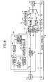
- a source digital video tape recorder (DVTR) 44 can supply the input fields to a key signal processor 46, a frame store 48 and a 60Hz, 2:1 to 24Hz, 1:1 motion compensated temporal interpolator 50.
- the key signal processor 46 includes a vertical interpolator 52 which produces the full frames B even for the even input fields a2, a4, a6, ...., and a field store 54 and vertical interpolator 56 which produces the full frames B odd for the odd input fields a1, a3, a5, ....
- the even and odd full frames B even , B odd are supplied to a subtractor 30 and modulus operator 32 and also to an adder 34, which supply an average intensity corrector 36, operating in the manner described above with reference to Figure 3 (but on full frames rather than fields) to produce the difference frames C.
- the differenced frames C can then be supplied to a 30Hz, 1:1 to 24Hz, 1:1 motion compensated temporal interpolator 57 as described in further detail with reference to Figure 70 of patent application 2249907 A, which produces the key frames D which are recorded on a DVTR 56.
- the frame store 48 operates to combine the input field pairs a1, a2; a3, a4; a5, a6; Vietnamese to produce the combined frames F, which can then be supplied to the interpolater 57 to produce the 30Hz, 1:1 to 24Hz, 1:1 converted frames G which are recorded on a DVTR 58.
- the interpolator 50 is as described with reference to Figures 1 to 48 of patent application GB 2231228 A and produces from the input fields a the 60Hz, 2:1 to 24Hz, 1:1 converted frames J which are recorded on a DVTR 60.
- the DVTR 56 can supply the recorded key frames D via a thresholder 62 to the control input of a multiplexer 64.
- the thresholder 62 may simply pass the most significant bit of the key frame video signal so that the threshold is set at 128 for 8-bit video data, or alternatively may involve a more complicated thresholding arrangement.
- the DVTRs 58, 60 can supply the 30Hz, 1:1 to 24Hz, 1:1 converted frames G and the 60Hz, 2:1 to 24Hz, 1:1 converted frames J in synchronism to the data inputs of the multiplexer 64, and thus the multiplexer 64 produces the matted output frames K which can be recorded on a DVTR 66.
- the elements of the arrangement of Figure 8 are controlled by a system controller 68 which supplies various control signals C1 to C10.
- input video having a composite acquisition of 30Hz, 1:1 and 60 Hz, 2:1 is processed so as to simulate acquisition at 24Hz, 1:1.
- the output frame rate need not be different to the input frame rate.
- a modified method could be used to convert video having a composite acquisition of 30Hz 1:1 and 60Hz, 2:1 so as to simulate acquisition wholly at 30 Hz, 1:1.
- motion compensated temporal interpolation would be used to generate, for each pair of input fields, a 30Hz, 1:1 full frame by combining fields, a 30Hz, 1:1 progressive scan converted frame using motion adaptive intra-field/inter-field interpolation, and a 30Hz difference frame, all three frames being temporally aligned by the motion compensated temporal interpolation processes.
- a key signal is generated by forming a difference signal and then converting the key signal by motion compensated temporal interpolation to the required output format.
- the key signal is then used to matte the two differently converted picture signals.
- the input composite video signal may have been post-produced using a key signal, and in the third example of the invention the key signal used in post-producing the picture signal is used alongside the picture signal. If the format of the key signal is different from the required output format, the key signal is converted to the output format, but apart from that the key signal can be used directly as the input to the multiplexer 64 in an apparatus somewhat like that shown in Figure 8.
- row A shows a series of 60Hz, 2:1 input picture frames A2 to A4, or fields a3 to a7, similar to row A of Figure 7.
- Row L shows the corresponding key signal fields l3 to l7 supplied with picture fields a3 to a7.
- the key signal is 60Hz, 2:1 rather than 30Hz, 1:1.
- the areas shown blank denote the picture area acquired at 30Hz, 1:1, and the areas which are cross-hatched denote the picture area acquired at 60Hz, 2:1.
- the fields of the key signal of row L nearest to the output frame temporal sitings are progressive scan converted to to produce a converted key signal as shown by row M of Figure 9.
- converted key signal frame M1 is produced by progressive scan conversion based on input key signal field I3, and converted key signal frame M2 is produced by progressive scan conversion based on input key signal field l5.
- the input picture fields of row A are also 60Hz, 2:1 to 24Hz, 1:1 converted and 30Hz, 1:1 to 24Hz, 1:1 converted to produce the frames of rows J and G, respectively, in the same way as described above with reference to Figures 6 and 7.
- the frames of row J can therefore suffer from incorrectly placed objects, and the frames of row G can suffer from loss of vertical resolution and double imaging.
- the frames of rows J and G are then matted using the converted key signal of row M to produce the output frames as shown in row K.
- the source DVTR 44 can supply the input picture fields a to the frame store 48 which can produce the full 30Hz, 1:1 picture frames F.
- the frames can then be converted to 24Hz, 1:1 by the motion compensated temporal interpolator 57, and the 30Hz, 1:1 to 24Hz, 1:1 converted picture frames G can be recorded on the DVTR 58.
- the source DVTR 44 can also supply the input picture fields a to the interpolator 50 where they can be converted using motion compensated temporal interpolation from 60Hz, 2:1 to 24Hz, 1:1, and the converted picture frames J can be recorded on the DVTR 60.
- the 60 Hz, 2:1 key signal fields are supplied by a DVTR 68 operating in synchronism with the DVTR 44 to a progressive scan converter 70 as described with reference to Figures 5 to 14 of patent application GB 2231228 A, which produces a progressive scan key frame M based on the first and third of every five input fields 1 and these converted key frames M are recorded by the DVTR 56.
- the three DVTRs 56, 68, 60 then reproduce the converted key frames M and the converted picture frames G, J in synchronism, and the multiplexer 64 selects pixels from the 30Hz, 1:1 to 24Hz, 1:1 converted frames G or the 60Hz, 2:1 to 24Hz, 1:1 converted frames J in dependence on the converted key signal M to produce the output 24Hz, 1:1 frames K which can be recorded on the DVTR 66.
- the system controller 68 produces various control signals C1 to C9 to control the elements of the apparatus.
- Figures 11 and 12 illustrate a further embodiment of the invention, which does not require a key signal to be supplied with the source video.
- the source video signal from a DVTR 100 operating in slow-motion is supplied both to a 60Hz, 2:1 to 24Hz, 1:1 motion compensated temporal interpolator 102 substantially as described in GB 2231228 A and to a 30Hz, 2:1 to 24Hz, 1:1 motion compensated temporal interpolator 104 substantially as described in GB 2249907 A.
- the output of the interpolator 102 or of the interpolator 104 is selected by a multiplexer 106 in dependence upon a signal supplied by a figure of merit comparator 108, and the frames output at less than real-time rate from the multiplexer 106 are grouped in a silicon frame recorder 110 before being recorded by an output DVTR 112 operating in burst mode.
- the 60Hz, 2:1 to 24Hz, 1:1 interpolator 102 comprises a progressive scan converter 114, which produces a progressive scan frame from each of the input fields by motion adaptive intra-field and/or inter-field interpolation.
- the progressive scan frames are supplied to a time base corrector 116a, which in turn supplies the frames at appropriate timings to a direct block matcher 118a, a motion vector selector 120a and an interpolator 122a.
- the direct block matcher 118a produces correlation surfaces, from which a motion vector estimator 124a deduces sets of motion vectors representing estimated motion of sample blocks in the picture and flags indicating how the motion vectors were deduced.
- the sets of motion vectors and their flags are then processed by a motion vector reducer 126a to produce reduced sets of motion vectors, which are passed to the motion vector selector 120a.
- the motion vector selector 120a assigns one of the motion vectors of the reduced set to each individual pixel in the sample block. In a first stage, motion vectors are assigned for each pixel in the progressive scan converted frames, and in a second stage, the motion vectors produced in the first stage are used to determine the motion vector for each pixel in the output frame which may be temporally sited part-way between a pair of the progressive scan converted frames. As described in detail with reference to Figures 36 to 48 of GB 2231228 A, various tests are carried out to determine each output frame related motion vector and degrees of match are assessed.
- a figure of merit FOMa is produced for each motion vector dependent upon the results of the tests carried out by the motion vector selector 120a, and the figure of merit values are supplied to the figure of merit comparator 108.
- the interpolator 122a interpolates the value of each output pixel in an output frame temporally sited between a pair of the progressive scan converted frames from the values of the pixels in the progressive scan converted frames offset from the location of the pixel in the output frame by amounts dependent upon the respective motion vector and temporally siting of the output frame.
- the 30Hz, 1:1 to 24Hz, 1:1 interpolator 104 is similar to the interpolator 102, except that instead of employing a motion adaptive progressive scan converter 114, progressive scan frames are produced by a field combiner 128 which interlaces the fields of each frame of the input video signal.
- the interpolator 104 includes a time base corrector 116b, a direct block matcher 118b, motion vector estimator 124b, motion vector reducer 126b, motion vector selector 120b and interpolator 122b operating in the manner described in GB 2231228 A and GB 2249907 A, but additionally, like the motion vector sector selector 120a, the motion vector selector 120b also produces for each motion vector a figure of merit FOMb which is supplied to a second input of the figure of merit comparator 108.
- the figure of merit comparator 108 compares the figures of merit FOMa, FOMb, and if FOMa ⁇ FOMb it produces a value 1 to cause the multiplexer 106 to select the pixel value from the 60Hz, 2:1 to 24Hz, 1:1 interpolator 102, whereas if FOMa ⁇ FOMb it produces a value 0 to cause the multiplexer 106 to select the pixel value from the 30Hz, 1:1 to 24Hz, 1:1 interpolator 104.
- the figure of merit comparator 108 may also use the two motion vectors Va, Vb associated with the figures of merit FOMa, FOMb is deciding which interpolator to select. For example, if both motion vectors are almost identical, it may be preferable to select the 60Hz, 2:1 to 24Hz, 2:1 comparator 102, even if the figures of merit suggest otherwise, because noise may have adversely affected the accuracy of the figure of merit FOMa.
- the operation of the figure of merit comparator 108 may be described as: IF (FOMa ⁇ FOMb) OR (
- Patent application GB 2231228 A describes the use of a motion vector post-processor, between the motion vector selector and the interpolator, which compares each motion vector with the motion vectors of surrounding pixels in an attempt to determine any spurious incorrect motion vectors, which may then be modified in dependence upon the surrounding motion vectors.
- Such motion vector post-processors may be provided in the arrangement of Figure 11 between the motion vector selectors 102a, 120b and the interpolators 122a, 122b.
- the figures of merit FOMa, FOMb may be modified by the motion vector post processors in dependence upon whether or not the respective motion vectors have been determined as likely to be incorrect and whether or not any action has been taken to correct them.
- the motion vector reducer 126a may be modified to detect such an alternating stream of motion vectors and either suppress them from being passed to the motion vector selector 120a, or alternatively assist the figure of merit selection.
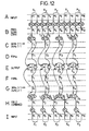
- Row A represents a series of five input frames A1 to A5 or ten fields a1 to a10 of 60Hz, 2:1 interlaced material, part of which was acquired at 60Hz, 2:1 interlace and part of which was acquired at 30 Hz, 1:1.
- the input fields a1 to a10 are each progressive scan converted by the converter 114 of Figure 11 to produce ten frames B1 to B10.
- a series of four 60Hz, 2:1 to 24Hz, 1:1 converted frames C1 to C4 is then produced.
- the first and third frames C1, C3 may be directly produced from the first and sixth progressive scan converted frames B1, B6.
- the second and fourth frames C2, C4 are produced by motion compensated temporal interpolation half-way between the third and fourth progressive scan converted frames B3, B4 and half-way between the eighth and ninth progressive scan converted frames B8, B9, respectively, and figure of merit frames D2, D4 are also produced associated with the motion vectors used in producing the frames C2, C4.
- frames C1 and C3 need not be produced by motion compensated temporal interpolation, the interpolator 102 is still employed to produce frames of motion vectors associated with the frames C1, C3 and respective frames of figures of merit D1, D3.
- Row I of Figure 12 also represents the series of five input frames A1 to A5 or ten input frames a1 to a10. Pairs of the fields are used by the field combiner 128 of Figure 11 to produce a series of five field combined frames H1 to H5. A series of four 30Hz, 1:1 to 24Hz, 1:1 converted frames G1 to G4 is then produced.
- the first converted frame G1 may be directly produced from the first field combined frame H1
- the second to fourth converted frames G2, G3, G4 are produced by motion compensated temporal interpolation one-quarter, one-half and three-quarters, respectively, of the way between field combined frames H2 and H3, H3 and H4, and H4 and H5, respectively.
- Figures of merit frames F2 to F4 are produced for each of the converted frames G2 to G4, and a figure of merit frame is also produced for the first frame G1 even though the first frame G1, need not be produced by motion compensated temporal interpolation.
Landscapes
- Engineering & Computer Science (AREA)
- Multimedia (AREA)
- Signal Processing (AREA)
- Television Systems (AREA)
Applications Claiming Priority (2)
| Application Number | Priority Date | Filing Date | Title |
|---|---|---|---|
| GB9205921 | 1992-03-18 | ||
| GB9205921A GB2265275B (en) | 1992-03-18 | 1992-03-18 | Digital video signal processing |
Publications (3)
| Publication Number | Publication Date |
|---|---|
| EP0561561A2 true EP0561561A2 (fr) | 1993-09-22 |
| EP0561561A3 EP0561561A3 (fr) | 1994-01-26 |
| EP0561561B1 EP0561561B1 (fr) | 1998-08-12 |
Family
ID=10712400
Family Applications (1)
| Application Number | Title | Priority Date | Filing Date |
|---|---|---|---|
| EP93301828A Expired - Lifetime EP0561561B1 (fr) | 1992-03-18 | 1993-03-10 | Traitement de signal vidéo numérique |
Country Status (5)
| Country | Link |
|---|---|
| US (1) | US5355169A (fr) |
| EP (1) | EP0561561B1 (fr) |
| JP (1) | JPH0646384A (fr) |
| DE (1) | DE69320223T2 (fr) |
| GB (1) | GB2265275B (fr) |
Cited By (2)
| Publication number | Priority date | Publication date | Assignee | Title |
|---|---|---|---|---|
| EP0648047A3 (fr) * | 1993-10-11 | 1995-06-21 | Thomson Consumer Electronics | Méthode et dispositif pour former un signal vidéo à l'aide d'un estimateur de mouvement et de voies de traitement de signal utilisant des procédés d'interpolation différents. |
| DE4419891B4 (de) * | 1994-06-07 | 2006-06-29 | Micronas Gmbh | Verfahren zur progressiven Konversion von Fernsehbildern mit Zeilensprung |
Families Citing this family (10)
| Publication number | Priority date | Publication date | Assignee | Title |
|---|---|---|---|---|
| GB2281835B (en) * | 1993-09-08 | 1998-04-22 | Sony Uk Ltd | Method and apparatus for synchronising video signals |
| US6014182A (en) * | 1997-10-10 | 2000-01-11 | Faroudja Laboratories, Inc. | Film source video detection |
| JP3567729B2 (ja) * | 1998-03-31 | 2004-09-22 | 日本ビクター株式会社 | 画像撮影装置 |
| US6697519B1 (en) * | 1998-10-29 | 2004-02-24 | Pixar | Color management system for converting computer graphic images to film images |
| JP2003299038A (ja) * | 2002-04-05 | 2003-10-17 | Sony Corp | フレーム変換装置及びフレーム変換方法 |
| EP1592247A1 (fr) * | 2004-04-30 | 2005-11-02 | Matsushita Electric Industrial Co., Ltd. | Compensation de mouvement en fonction du type de block |
| JP4366277B2 (ja) * | 2004-09-21 | 2009-11-18 | キヤノン株式会社 | 撮像装置及びその制御方法 |
| JP4282645B2 (ja) * | 2005-08-31 | 2009-06-24 | 株式会社東芝 | 撮像装置 |
| DE102006001079B4 (de) * | 2006-01-09 | 2020-08-06 | Carl Zeiss Ag | HMD-Vorrichtung und Anzeigeverfahren dafür |
| GB2552526A (en) | 2016-07-28 | 2018-01-31 | Siemens Ag | Electrochemical method of ammonia generation |
Family Cites Families (8)
| Publication number | Priority date | Publication date | Assignee | Title |
|---|---|---|---|---|
| GB1052438A (fr) * | 1965-02-04 | |||
| DE3851718T2 (de) * | 1987-06-09 | 1995-01-26 | Sony Corp | Fernsehnormwandler. |
| GB2231228B (en) * | 1989-04-27 | 1993-09-22 | Sony Corp | Video signal to photographic film conversion |
| JPH0385976A (ja) * | 1989-08-30 | 1991-04-11 | Sanyo Electric Co Ltd | テレビジョン方式変換装置 |
| US5187575A (en) * | 1989-12-29 | 1993-02-16 | Massachusetts Institute Of Technology | Source adaptive television system |
| GB9001079D0 (en) * | 1990-01-17 | 1990-03-14 | Avesco Plc | Standards conversion |
| AU8905591A (en) * | 1990-11-16 | 1992-06-11 | Rank Cintel Limited | Video systems |
| EP0514012A3 (en) * | 1991-04-15 | 1993-11-18 | Vistek Electronics | Method and apparatus for the standard conversion of an image signal |
-
1992
- 1992-03-18 GB GB9205921A patent/GB2265275B/en not_active Expired - Fee Related
-
1993
- 1993-03-10 EP EP93301828A patent/EP0561561B1/fr not_active Expired - Lifetime
- 1993-03-10 DE DE69320223T patent/DE69320223T2/de not_active Expired - Fee Related
- 1993-03-12 US US08/031,109 patent/US5355169A/en not_active Expired - Lifetime
- 1993-03-18 JP JP5058286A patent/JPH0646384A/ja active Pending
Cited By (2)
| Publication number | Priority date | Publication date | Assignee | Title |
|---|---|---|---|---|
| EP0648047A3 (fr) * | 1993-10-11 | 1995-06-21 | Thomson Consumer Electronics | Méthode et dispositif pour former un signal vidéo à l'aide d'un estimateur de mouvement et de voies de traitement de signal utilisant des procédés d'interpolation différents. |
| DE4419891B4 (de) * | 1994-06-07 | 2006-06-29 | Micronas Gmbh | Verfahren zur progressiven Konversion von Fernsehbildern mit Zeilensprung |
Also Published As
| Publication number | Publication date |
|---|---|
| GB2265275B (en) | 1996-01-03 |
| JPH0646384A (ja) | 1994-02-18 |
| GB9205921D0 (en) | 1992-04-29 |
| EP0561561B1 (fr) | 1998-08-12 |
| GB2265275A (en) | 1993-09-22 |
| DE69320223T2 (de) | 1999-03-04 |
| DE69320223D1 (de) | 1998-09-17 |
| EP0561561A3 (fr) | 1994-01-26 |
| US5355169A (en) | 1994-10-11 |
Similar Documents
| Publication | Publication Date | Title |
|---|---|---|
| AU643565B2 (en) | pideo image processing | |
| EP0395275B1 (fr) | Traitement de signal vidéo dépendant du mouvement | |
| US6104755A (en) | Motion detection using field-difference measurements | |
| US5005077A (en) | Motion dependent video signal processing | |
| US5642170A (en) | Method and apparatus for motion compensated interpolation of intermediate fields or frames | |
| EP0395264B1 (fr) | Traitement de signal vidéo dépendant du mouvement | |
| GB2256341A (en) | Video signal processing | |
| JPH08508138A (ja) | 動き補正を伴う映像信号処理 | |
| EP0561561A2 (fr) | Traitement de signal vidéo numérique | |
| JPS60229594A (ja) | 動物体の動き内挿装置 | |
| EP0395263B1 (fr) | Traitement de signal vidéo dépendant du mouvement | |
| EP0395266B1 (fr) | Traitement de signal vidéo dépendant du mouvement | |
| EP1039746B1 (fr) | Procédé et dispositif pour l'interpolation de lignes | |
| EP0395272B1 (fr) | Traitement de signal vidéo dépendant du mouvement | |
| JP3604752B2 (ja) | 動きベクトル検出装置および方法 | |
| JPS61139175A (ja) | ビデオ信号変換方法 | |
| JP4140091B2 (ja) | 画像情報変換装置および画像情報変換方法 | |
| JPH0462234B2 (fr) | ||
| JPH06326980A (ja) | 動き補償映像信号処理方式 | |
| EP0675643B1 (fr) | Méthode et appareil de réduction d'artefacts de conversion | |
| JP3871360B2 (ja) | ビデオ信号処理装置及び方法 | |
| JP2507178B2 (ja) | 動き検出方法及び動き検出装置 | |
| JP4470324B2 (ja) | 画像信号変換装置および方法 | |
| JPH0622210A (ja) | ビデオ−フィルム変換シミュレーション方法及び装置 | |
| JPH08223540A (ja) | 動きベクトルを用いた動き内挿方法および動き内挿回路ならびに動きベクトル検出方法および動きベクトル検出回路 |
Legal Events
| Date | Code | Title | Description |
|---|---|---|---|
| PUAI | Public reference made under article 153(3) epc to a published international application that has entered the european phase |
Free format text: ORIGINAL CODE: 0009012 |
|
| AK | Designated contracting states |
Kind code of ref document: A2 Designated state(s): DE FR |
|
| PUAL | Search report despatched |
Free format text: ORIGINAL CODE: 0009013 |
|
| AK | Designated contracting states |
Kind code of ref document: A3 Designated state(s): DE FR |
|
| RAP3 | Party data changed (applicant data changed or rights of an application transferred) |
Owner name: SONY UNITED KINGDOM LIMITED |
|
| 17P | Request for examination filed |
Effective date: 19940620 |
|
| 17Q | First examination report despatched |
Effective date: 19960923 |
|
| GRAG | Despatch of communication of intention to grant |
Free format text: ORIGINAL CODE: EPIDOS AGRA |
|
| GRAG | Despatch of communication of intention to grant |
Free format text: ORIGINAL CODE: EPIDOS AGRA |
|
| GRAH | Despatch of communication of intention to grant a patent |
Free format text: ORIGINAL CODE: EPIDOS IGRA |
|
| GRAH | Despatch of communication of intention to grant a patent |
Free format text: ORIGINAL CODE: EPIDOS IGRA |
|
| GRAA | (expected) grant |
Free format text: ORIGINAL CODE: 0009210 |
|
| AK | Designated contracting states |
Kind code of ref document: B1 Designated state(s): DE FR |
|
| REF | Corresponds to: |
Ref document number: 69320223 Country of ref document: DE Date of ref document: 19980917 |
|
| ET | Fr: translation filed | ||
| PLBE | No opposition filed within time limit |
Free format text: ORIGINAL CODE: 0009261 |
|
| STAA | Information on the status of an ep patent application or granted ep patent |
Free format text: STATUS: NO OPPOSITION FILED WITHIN TIME LIMIT |
|
| 26N | No opposition filed | ||
| PGFP | Annual fee paid to national office [announced via postgrant information from national office to epo] |
Ref country code: DE Payment date: 20050304 Year of fee payment: 13 |
|
| PGFP | Annual fee paid to national office [announced via postgrant information from national office to epo] |
Ref country code: FR Payment date: 20050308 Year of fee payment: 13 |
|
| PG25 | Lapsed in a contracting state [announced via postgrant information from national office to epo] |
Ref country code: DE Free format text: LAPSE BECAUSE OF NON-PAYMENT OF DUE FEES Effective date: 20061003 |
|
| REG | Reference to a national code |
Ref country code: FR Ref legal event code: ST Effective date: 20061130 |
|
| PG25 | Lapsed in a contracting state [announced via postgrant information from national office to epo] |
Ref country code: FR Free format text: LAPSE BECAUSE OF NON-PAYMENT OF DUE FEES Effective date: 20060331 |