EP0563018B1 - Equipment for the joining of sections converging at a corner of a metal frame, with gluing between the sections and the internal bracket - Google Patents
Equipment for the joining of sections converging at a corner of a metal frame, with gluing between the sections and the internal bracket Download PDFInfo
- Publication number
- EP0563018B1 EP0563018B1 EP93830117A EP93830117A EP0563018B1 EP 0563018 B1 EP0563018 B1 EP 0563018B1 EP 93830117 A EP93830117 A EP 93830117A EP 93830117 A EP93830117 A EP 93830117A EP 0563018 B1 EP0563018 B1 EP 0563018B1
- Authority
- EP
- European Patent Office
- Prior art keywords
- sections
- bracket
- devices
- drilling
- corner
- Prior art date
- Legal status (The legal status is an assumption and is not a legal conclusion. Google has not performed a legal analysis and makes no representation as to the accuracy of the status listed.)
- Expired - Lifetime
Links
Images


Classifications
-
- E—FIXED CONSTRUCTIONS
- E06—DOORS, WINDOWS, SHUTTERS, OR ROLLER BLINDS IN GENERAL; LADDERS
- E06B—FIXED OR MOVABLE CLOSURES FOR OPENINGS IN BUILDINGS, VEHICLES, FENCES OR LIKE ENCLOSURES IN GENERAL, e.g. DOORS, WINDOWS, BLINDS, GATES
- E06B3/00—Window sashes, door leaves, or like elements for closing wall or like openings; Layout of fixed or moving closures, e.g. windows in wall or like openings; Features of rigidly-mounted outer frames relating to the mounting of wing frames
- E06B3/96—Corner joints or edge joints for windows, doors, or the like frames or wings
- E06B3/9612—Corner joints or edge joints for windows, doors, or the like frames or wings by filling in situ the hollow ends of the abutted frame members with a hardenable substance
-
- B—PERFORMING OPERATIONS; TRANSPORTING
- B21—MECHANICAL METAL-WORKING WITHOUT ESSENTIALLY REMOVING MATERIAL; PUNCHING METAL
- B21D—WORKING OR PROCESSING OF SHEET METAL OR METAL TUBES, RODS OR PROFILES WITHOUT ESSENTIALLY REMOVING MATERIAL; PUNCHING METAL
- B21D53/00—Making other particular articles
- B21D53/74—Making other particular articles frames for openings, e.g. for windows, doors, handbags
- B21D53/745—Joining mitred profiles comprising punching the profiles on a corner-angle connecting piece
-
- F—MECHANICAL ENGINEERING; LIGHTING; HEATING; WEAPONS; BLASTING
- F16—ENGINEERING ELEMENTS AND UNITS; GENERAL MEASURES FOR PRODUCING AND MAINTAINING EFFECTIVE FUNCTIONING OF MACHINES OR INSTALLATIONS; THERMAL INSULATION IN GENERAL
- F16B—DEVICES FOR FASTENING OR SECURING CONSTRUCTIONAL ELEMENTS OR MACHINE PARTS TOGETHER, e.g. NAILS, BOLTS, CIRCLIPS, CLAMPS, CLIPS OR WEDGES; JOINTS OR JOINTING
- F16B11/00—Connecting constructional elements or machine parts by sticking or pressing them together, e.g. cold pressure welding
- F16B11/006—Connecting constructional elements or machine parts by sticking or pressing them together, e.g. cold pressure welding by gluing
-
- B—PERFORMING OPERATIONS; TRANSPORTING
- B29—WORKING OF PLASTICS; WORKING OF SUBSTANCES IN A PLASTIC STATE IN GENERAL
- B29C—SHAPING OR JOINING OF PLASTICS; SHAPING OF MATERIAL IN A PLASTIC STATE, NOT OTHERWISE PROVIDED FOR; AFTER-TREATMENT OF THE SHAPED PRODUCTS, e.g. REPAIRING
- B29C2793/00—Shaping techniques involving a cutting or machining operation
- B29C2793/0045—Perforating
Definitions
- the invention relates to the technique for the formation of metal frames, using sections which are usually mitred, converge at the corners, and are connected there by means of brackets housed within the sections.
- the connection is made by joints using a shape fit provided by the chamfering of the walls - most commonly the external walls - of the sections to provide deformations with perforations if necessary, and to create areas which bear against the shoulders of the bracket. More or less automated equipment exists to execute these joints.
- the object of the invention is an equipment for the joining of sections converging at a corner with the aid of an internal bracket, for the formation of metal frames and the like.
- the equipment according to the invention is of the type comprising - at a substantially horizontal seat for the components of the frame that are to be assembled - chamfering devices capable of deforming an external wall of each section to bear against a corresponding stop on the bracket, at least one drilling device and at least one device for injecting through the said hole a liquid adhesive capable of securing the fastening between the bracket and the sections.
- the element for carrying the drilling and injection devices is movable at right angles with respect to said seat to bring first the drilling device or devices and then the adhesive injection device or devices into the operating position.
- two said drilling devices and two corresponding said injection devices are disposed symmetrically about the plane bisecting the corner of the frame being constructed and capable of acting on the external sides of the two sections next to the arms of the bracket.
- a guide system orthogonal to the bisecting plane may be provided on the said element, to move symmetrically in and out two sliding supports, each of which carries a drilling device and an injection device.
- the said guide system may be carried in turn by a sliding block which is movable on the said element to approach and move away from the location for the components to be assembled.
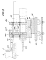
- Figs. 1 to 6 show an embodiment in which a pair of chamfering devices of a known type and a pair of devices for injecting an adhesive are provided.
- 1 indicates the base structure for the support of the sections P which converge at the corner to be formed and are to be connected by means of a bracket S.
- the flat member 1 forms part of a structure which also comprises vertical guides 3 connected below by a horizontal plate 5.
- chamfering devices indicated in a general way by 7 and disposed symmetrically about a bisecting plane which coincides with the plane of joining of the mitred surfaces of the two sections B for the formation of the corner of the frame with the aid of the bracket S; 7A indicates the chamfering tools which act on the external surfaces of the sections P to cause their deformation or possibly their perforation in order to ensure the fastening of the bracket S by the bearing of the deformed parts of the sections P against shoulders formed by the bracket S and corresponding to the deformations which form supporting and force-fitting catches and which are produced by the chamfering tools 7A.
- the positions of these devices 7 may be adjusted, by a method known in these machines, according to the types of bracket which may be used on different occasions by the user.
- a replaceable bracket or fork 9 whose position is adjustable by means of a plate 10 and a support 12 which forms guides for pins 14 which may be inserted in slides which are also formed by the support 12, is provided immediately above the supporting plane formed by the structure 1; 16 indicates a knob for the engagement by screwing of the replaceable bracket or fork assembly 9, 10; the bracket or fork 9 is used to determine the position of the sections P converging at the corner to be formed and engaging with the connecting bracket S to form the frame.
- a vertically slidable and driven element 20 is mounted on the vertical guides 3 so that it can reach two predetermined positions along the guides 3 by means of a cylinder and piston system 22, the end of whose rod 22A is engaged rotatably at 24 with a vertical adjusting screw 26 whose thread is engaged with a bush 28 which is integral with the said element 20; by adjusting the screw 26 with a spanner, the two positions of the element 20 are adjusted with respect to the guides 3, whose positions are reached by the action of the cylinder and piston system 22, 22A with a fixed spacing between the said two positions; this spacing corresponds to the centre spacing between the drilling device and the injection device in each of the two pairs of devices which are provided on the element 20; by means of the adjustment obtained with the screw 26 and the bush 28 it is possible to adjust the active positions of the two drilling and injection devices which are carried by the said element 20 in the way indicated below, in such a way as to match the two positions to the shape and dimensional characteristics of the
- the element 20 forms a dovetailed sliding guide 20A which is orientated parallel to the plane bisecting the corner to be formed with the sections P, this bisecting plane corresponding to the plane of the section II-II in Fig. 1 and to the plane A-A indicated also in Fig. 3.
- a sliding block 30, which can slide along the guides 20A and consequently in the said bisecting plane and whose position may be adjusted by means of a screw knob 32, is fitted on the guides 20A of the element 20.
- the sliding block 30 has an elongated slot which permits the passage of the adjusting screw 26 for the vertical adjustment of the element 20 and the displacement of the sliding block 30 in the said bisecting plane passing through A-A.
- the sliding block 30 has dovetailed guides 38 which are orthogonal to the bisecting plane passing through A-A and which are disposed symmetrically about the said plane and aligned with each other.
- a support 40 is slidable on each of the said guides 38 and its position may be adjusted; the two supports 40 are inclined symmetrically about the plane passing through A-A so that they may be orientated in directions converging on the fork 9, the sections P to be joined and the bracket S for connecting the said sections.
- a double-threaded rod 42 is engaged in corresponding threaded holes in the two supports 40; the said rod 42, whose axis is orthogonal to the plane passing through A-A and therefore parallel to the direction of the two guides 38, is engaged rotatably but with axial restraint with a lug 44 carried by the sliding block 30.
- a knurled disc 46 integral with the double-threaded rod 42 it is possible to manoeuvre the said rod and thereby adjust the positions of the two supports 40 symmetrically along the guides 38, in such a way as to keep the supports symmetrical about the bisecting plane passing through A-A.
- Each of the supports 40 which may be adjusted along the corresponding guides 38, has two vertical plates 40A which in their lower parts form sliding housings for an injection cartridge 50 intended by means of its nozzle 50a to supply at the correct time a specified quantity of adhesive for the purposes stated below.
- the plates 40A also form sliding housings for a tool 52 with a drill bit 52A and with a pneumatic motor 52B for the rotation of the said bit 52A.
- the devices 50 and 52 are carried by a vertical plate 54 which is slidably supported and guided by cylindrical guides 40C which extend between the two plates 40A and are parallel to the axes of the device 52 and of the cartridge 50.
- the plate 54 and consequently the device 52 and the cartridge 50 are movable along the guides 40C by means of a threaded rod 58 engaged in a bush of the plate 54 and caused to rotate by a step-by-step motor 60 carried by one of the plates 40A.
- a threaded rod 58 engaged in a bush of the plate 54 and caused to rotate by a step-by-step motor 60 carried by one of the plates 40A.
- the motor 60 By means of the activation of the motor 60, therefore, it is possible to advance and withdraw both the bit 52A of the drilling device 52 and the nozzle 50A of the adhesive injection cartridge 50, in an adjustable way and in particular with adjustable speed, to predetermined positions which are also adjustable.
- This disposition is provided in each of the two symmetrical supports 40, 40A which are adjustable to advance and withdraw, while remaining constantly parallel to themselves, by means of the threaded rod 42 which drives them simultaneously and symmetrically.
- the devices 50, 52 of the two said pairs are then adjustable in the direction of the bisecting plane passing through A-A by means of the movement of the sliding block 30 and are movable to two alternative positions in the vertical direction by the cylinder and piston system 22, the two positions being the operating positions of the drill bit 52A (of the device 52) and of the nozzle 50A (of the injection cartridge 50) respectively.
- These operating positions are adjustable by means of the adjusting screw 26 which changes the relative position of the end of the rod 22A of the cylinder and piston system 22, 22A with respect to the element 20 in which the screw 26 is engaged.
- the operating positions of the drills and of the injectors are preferably displaced from the positions of the chamfering tools. By withdrawing the tools 7A, it is possible to use the drills and injectors even at points not remote from the chamfering areas.
- a hole is made with the corresponding bit 52A of the device 52, and adhesive is then injected by means of the nozzle 50A of the corresponding cartridge 50, at a predetermined position along each of the two converging sections P, after the whole element 20 has been raised by the cylinder and piston 22 from the lowered position, corresponding to the position of drilling with the bits 52A, to the raised position corresponding to the injection of the adhesive by means of the nozzle 50A into the corresponding hole formed by the appropriate bit 52A.
- the advance and withdrawal of the bit 52A and the nozzle 50A are executed by the motor 60 which is a step-by-step motor to establish the exact position of deceleration and subsequently of halting of the advance for drilling and for injection respectively, while the drill bit 52A is driven by its own motor 52B which for'example may be a pneumatic motor activated at the correct time.
- the nozzle 50A is activated by an appropriate actuator which for example may be pneumatic, with a suitable program.
Landscapes
- Engineering & Computer Science (AREA)
- Mechanical Engineering (AREA)
- General Engineering & Computer Science (AREA)
- Civil Engineering (AREA)
- Structural Engineering (AREA)
- Adhesives Or Adhesive Processes (AREA)
- Connection Of Plates (AREA)
- Joining Of Corner Units Of Frames Or Wings (AREA)
- Standing Axle, Rod, Or Tube Structures Coupled By Welding, Adhesion, Or Deposition (AREA)
- Catching Or Destruction (AREA)
Applications Claiming Priority (2)
| Application Number | Priority Date | Filing Date | Title |
|---|---|---|---|
| ITFI920076 | 1992-03-26 | ||
| ITFI920076A IT1259636B (it) | 1992-03-26 | 1992-03-26 | Metodo ed attrezzatura per l'accoppiamento di profilati concorrenti ad un angolo di un telaio di infisso metallico, con incollaggio fra i profilati e la squadretta interna |
Publications (3)
| Publication Number | Publication Date |
|---|---|
| EP0563018A2 EP0563018A2 (en) | 1993-09-29 |
| EP0563018A3 EP0563018A3 (en) | 1993-11-10 |
| EP0563018B1 true EP0563018B1 (en) | 1997-02-19 |
Family
ID=11350030
Family Applications (1)
| Application Number | Title | Priority Date | Filing Date |
|---|---|---|---|
| EP93830117A Expired - Lifetime EP0563018B1 (en) | 1992-03-26 | 1993-03-25 | Equipment for the joining of sections converging at a corner of a metal frame, with gluing between the sections and the internal bracket |
Country Status (3)
| Country | Link |
|---|---|
| EP (1) | EP0563018B1 (it) |
| ES (1) | ES2098019T3 (it) |
| IT (1) | IT1259636B (it) |
Families Citing this family (11)
| Publication number | Priority date | Publication date | Assignee | Title |
|---|---|---|---|---|
| IT1277805B1 (it) * | 1995-01-18 | 1997-11-12 | Atla Coop Scarl | Attrezzatura per accoppiare profilati concorrenti ad angolo in un telaio metallico per infissi |
| IT1278737B1 (it) * | 1995-08-04 | 1997-11-27 | Atla Coop Scarl | Una apparecchiatura per assicurare con l'ausilio di collanti i componenti di un telaio per infissi in profilati metallici, in |
| IT1278738B1 (it) * | 1995-08-04 | 1997-11-27 | Atla Coop Scarl | Attrezzatura per alimentazione dei componenti di un collante cosidetto a bicomponenti, da miscelare all'atto dell'iniezione |
| DE19605991A1 (de) * | 1996-02-17 | 1997-08-21 | Pressta Eisele Gmbh | Eckverbindungsmaschine zur Herstellung von Fenster- und/oder Türrahmen |
| BE1012394A3 (nl) * | 1998-09-29 | 2000-10-03 | Brochez Alain | Hoekverbinding en werkwijze voor het vervaardigen van dergelijke hoekverbinding, alsmede insteekhoekstukken om zulke hoekverbinding te realiseren. |
| DE10118791B4 (de) * | 2001-04-18 | 2012-06-21 | Adrian Kosak | Verbindungselement |
| ITMO20020193A1 (it) * | 2002-07-09 | 2004-01-09 | Oemme Spa | Macchina per la giunzione d'angolo di semilavorati per l'assemblaggiodi profilati per serramenti e simili |
| EP1459821A1 (en) * | 2003-03-18 | 2004-09-22 | ATLA COOP. Soc. Coop. a r.l. | Device for crimping machine |
| FR2917657B1 (fr) * | 2007-06-19 | 2009-10-02 | Jean Charles Renaud | Machine d'assemblage de profiles tubulaires |
| CN103510807A (zh) * | 2012-06-15 | 2014-01-15 | 上海德意达门窗有限公司 | 一种铝型材双刀组角的加工方法 |
| CN105149163A (zh) * | 2015-08-17 | 2015-12-16 | 山东安德广厦新能源科技有限公司 | 一种门窗组角连接型材及其注胶方法 |
Family Cites Families (4)
| Publication number | Priority date | Publication date | Assignee | Title |
|---|---|---|---|---|
| DE1914488A1 (de) * | 1969-03-21 | 1970-10-01 | Schenning Theodor Karl Peter | Eckverbindung fuer auf Gehrung geschnittene Hohl- oder U-Profile,insbesondere fuer Fenster- und Tuerrahmen |
| DE2510884C3 (de) * | 1975-03-13 | 1978-07-27 | Loth, Hermann, 6603 Sulzbach | Vorrichtung zum Verbinden von zwei auf Gehrung geschnittenen Metallprofilstäben |
| DE2522523A1 (de) * | 1975-05-21 | 1976-12-02 | Hans Rottner Kg Haro Maschinen | Verfahren und vorrichtung zum verbinden der ecken von auf gehrung geschnittenen leichtmetall-hohlprofilen |
| SE457368B (sv) * | 1985-08-08 | 1988-12-19 | Nystroems Beslag Ab | Saett att vid skarvning av haalprofiler med hjaelp av skarvstycken foerse skarvstycket med bindemedel och anordning foer genomfoerande av detta saett |
-
1992
- 1992-03-26 IT ITFI920076A patent/IT1259636B/it active IP Right Grant
-
1993
- 1993-03-25 EP EP93830117A patent/EP0563018B1/en not_active Expired - Lifetime
- 1993-03-25 ES ES93830117T patent/ES2098019T3/es not_active Expired - Lifetime
Also Published As
| Publication number | Publication date |
|---|---|
| EP0563018A3 (en) | 1993-11-10 |
| EP0563018A2 (en) | 1993-09-29 |
| ES2098019T3 (es) | 1997-04-16 |
| ITFI920076A1 (it) | 1993-09-26 |
| IT1259636B (it) | 1996-03-25 |
| ITFI920076A0 (it) | 1992-03-26 |
Similar Documents
| Publication | Publication Date | Title |
|---|---|---|
| EP0563018B1 (en) | Equipment for the joining of sections converging at a corner of a metal frame, with gluing between the sections and the internal bracket | |
| EP1231018B2 (en) | Portable multi-axis machine | |
| RU2032540C1 (ru) | Устройство для сверления отверстий в плитах из камня | |
| DE3636710A1 (de) | Verfahren und einrichtung zur montage eines rotationsring-kreiskolbenverdichters | |
| US4234155A (en) | Tool stand | |
| CN115229229B (zh) | 机加工定距调节控制系统及方法 | |
| KR102641281B1 (ko) | 자동 피스체결을 위한 커튼월의 멀리언 연결구 자동 가이드 시스템 | |
| JPS61164705A (ja) | チヤツクのフエースジヨー交換装置 | |
| KR20240069057A (ko) | 프레임과 브라켓의 나사못 자동 체결장치 | |
| CN107900409B (zh) | 单钻头气电一体钻孔装置 | |
| CN210336321U (zh) | 一种榫接柜门组装机 | |
| CN210306156U (zh) | 薄壁钻焊接机 | |
| CN220943313U (zh) | 深孔钻架 | |
| JPS60150922A (ja) | ボルト類の仮組み装置 | |
| CN118952090A (zh) | 一种旋转式组装夹具及其使用方法 | |
| CN213796140U (zh) | 机械式对位器 | |
| CN214444714U (zh) | 一种数控机床的定位装置 | |
| CN203077369U (zh) | 一种可调式mwd扶正块切削工具 | |
| CN103796780B (zh) | 镗床 | |
| JPH0753955Y2 (ja) | 射出成形機の射出装置用ガイド部材調整装置 | |
| JPS599301B2 (ja) | 横型インデツクス | |
| CN220909607U (zh) | 一种煤矿钻孔定位装置 | |
| CN219725763U (zh) | 大尺寸零件孔内珩磨加工设备 | |
| US20220241917A1 (en) | Workpiece Orientation Mechanism | |
| CN219686150U (zh) | 一种建筑开槽加工器械 |
Legal Events
| Date | Code | Title | Description |
|---|---|---|---|
| PUAI | Public reference made under article 153(3) epc to a published international application that has entered the european phase |
Free format text: ORIGINAL CODE: 0009012 |
|
| PUAL | Search report despatched |
Free format text: ORIGINAL CODE: 0009013 |
|
| AK | Designated contracting states |
Kind code of ref document: A2 Designated state(s): ES FR GR |
|
| AK | Designated contracting states |
Kind code of ref document: A3 Designated state(s): ES FR GR |
|
| 17P | Request for examination filed |
Effective date: 19940414 |
|
| 17Q | First examination report despatched |
Effective date: 19950406 |
|
| GRAG | Despatch of communication of intention to grant |
Free format text: ORIGINAL CODE: EPIDOS AGRA |
|
| GRAH | Despatch of communication of intention to grant a patent |
Free format text: ORIGINAL CODE: EPIDOS IGRA |
|
| GRAH | Despatch of communication of intention to grant a patent |
Free format text: ORIGINAL CODE: EPIDOS IGRA |
|
| GRAA | (expected) grant |
Free format text: ORIGINAL CODE: 0009210 |
|
| AK | Designated contracting states |
Kind code of ref document: B1 Designated state(s): ES FR GR |
|
| PG25 | Lapsed in a contracting state [announced via postgrant information from national office to epo] |
Ref country code: GR Free format text: LAPSE BECAUSE OF FAILURE TO SUBMIT A TRANSLATION OF THE DESCRIPTION OR TO PAY THE FEE WITHIN THE PRESCRIBED TIME-LIMIT Effective date: 19970219 |
|
| REG | Reference to a national code |
Ref country code: ES Ref legal event code: FG2A Ref document number: 2098019 Country of ref document: ES Kind code of ref document: T3 |
|
| ET | Fr: translation filed | ||
| PLBE | No opposition filed within time limit |
Free format text: ORIGINAL CODE: 0009261 |
|
| STAA | Information on the status of an ep patent application or granted ep patent |
Free format text: STATUS: NO OPPOSITION FILED WITHIN TIME LIMIT |
|
| 26N | No opposition filed | ||
| PGFP | Annual fee paid to national office [announced via postgrant information from national office to epo] |
Ref country code: FR Payment date: 20100416 Year of fee payment: 18 Ref country code: ES Payment date: 20100331 Year of fee payment: 18 |
|
| REG | Reference to a national code |
Ref country code: FR Ref legal event code: ST Effective date: 20111130 |
|
| PG25 | Lapsed in a contracting state [announced via postgrant information from national office to epo] |
Ref country code: FR Free format text: LAPSE BECAUSE OF NON-PAYMENT OF DUE FEES Effective date: 20110331 |
|
| REG | Reference to a national code |
Ref country code: ES Ref legal event code: FD2A Effective date: 20120423 |
|
| PG25 | Lapsed in a contracting state [announced via postgrant information from national office to epo] |
Ref country code: ES Free format text: LAPSE BECAUSE OF NON-PAYMENT OF DUE FEES Effective date: 20110326 |