EP0563190B1 - Visualisation de donnees interactive - Google Patents
Visualisation de donnees interactive Download PDFInfo
- Publication number
- EP0563190B1 EP0563190B1 EP92901808A EP92901808A EP0563190B1 EP 0563190 B1 EP0563190 B1 EP 0563190B1 EP 92901808 A EP92901808 A EP 92901808A EP 92901808 A EP92901808 A EP 92901808A EP 0563190 B1 EP0563190 B1 EP 0563190B1
- Authority
- EP
- European Patent Office
- Prior art keywords
- physical
- icons
- attributes
- visual
- physical attributes
- Prior art date
- Legal status (The legal status is an assumption and is not a legal conclusion. Google has not performed a legal analysis and makes no representation as to the accuracy of the status listed.)
- Expired - Lifetime
Links
Images

Classifications
-
- G—PHYSICS
- G06—COMPUTING OR CALCULATING; COUNTING
- G06F—ELECTRIC DIGITAL DATA PROCESSING
- G06F3/00—Input arrangements for transferring data to be processed into a form capable of being handled by the computer; Output arrangements for transferring data from processing unit to output unit, e.g. interface arrangements
- G06F3/01—Input arrangements or combined input and output arrangements for interaction between user and computer
- G06F3/048—Interaction techniques based on graphical user interfaces [GUI]
- G06F3/0481—Interaction techniques based on graphical user interfaces [GUI] based on specific properties of the displayed interaction object or a metaphor-based environment, e.g. interaction with desktop elements like windows or icons, or assisted by a cursor's changing behaviour or appearance
Definitions
- This invention relates generally to the field of computer data analysis and more particularly to a method and to an arrangement for visualizing a large number of different physical attributes of one or more data objects residing in at least one date base of a computer memory.
- a subject about which information is collected in one or more databases in computer memory can be referred to as a data object.
- characteristics or categories of information about one or more data objects about which a human operator may be interested In the ensuing description, such characteristics or categories will be called “physical attributes" in order to distinguish them from the graphic characteristics of images appearing on the screen of a display monitor, which will be called “visual attributes.”
- icons have sometimes been displayed on the screen of a computer monitor to convey information to a human operator about a limited number of a data object's physical attributes at once through such graphic characteristics or visual attributes as shape, size, color, pattern, or location.
- graphic characteristics or visual attributes as shape, size, color, pattern, or location.
- icons or "sprites" representing people, vehicles, or the like of many different kinds change many facets of their appearance (visible attributes) to indicate their current physical state.
- a major drawback is that such icons have only predetermined functionality. Even though that functionality may be both diverse and relatively extensive, the fact that it is fixed is a severe limitation upon its use in the analysis of the contents of complex databases.
- the present invention overcomes many of the limitations of the prior art by making the visualization process interactive on the part of a human operator and by using at least two separate icons which may be present on the screen of a computer display monitor contemporaneously and which can be thought of as giving a data object semi-intelligent characteristics. As displayed on the screen of a monitor, the data object may thus be looked upon, in this sense, as a "smart object.”
- the invention aids an operator, through an interactive method and arrangement, in visualizing a plurality of different physical attributes of a data object residing in at least one database in computer memory.
- the invention takes the form of a method and of an arrangement as set out in claims 1 and 6 respectively.
- one or more control panels may be generated on the screen of the display monitor showing both the individual physical attributes making up the currently selected sub-set of physical attributes and the graphic characteristics in the visual attribute icon to which they have been assigned.
- a human operator may thus display a specifically limited sub-set of physical attributes at any one time and change either the identity of the particular physical attributes displayed or the visual attributes by which they are displayed, or both.
- the invention is particularly advantageous when physical attributes of a plurality of data objects are being subject to analysis.
- the human operator may thus compare instantly the status of different data objects and be in a position to identify trends, patterns, or anomalies the exact nature of which might have been impossible to anticipate.
- the invention takes the form of methods and arrangements which comprise generation of an individual visual attribute icon on the screen of a display monitor for each of the data objects to be examined, the visual attribute icons each displaying values of a sub-set of the total physical attributes of the data objects in terms of different graphic characteristics or visual attributes, generation of a physical attribute icon for each of the data objects, selectively displaying the physical attribute icons on the screen of the display monitor, each of the physical attribute icons identifying all the physical attributes of its data object available in computer memory, selection from the physical attribute icons of the sub-set of physical attributes to be displayed in the visual attribute icons, assignment of respectively different graphic characteristics or visual attributes to each member of the selected sub-set, and display of the values of the selected sub-set of physical attributes in the visual attribute icons in terms of different visual attributes.
- one or more control panels may be generated on the screen of the display monitor showing both the individual physical attributes making up the currently selected sub-set of physical attributes and the graphic characteristics in the visual attribute icons to when they have been assigned.
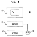
- FIG. 1 is a block diagram of a conventional computer assembly 11 of a type to which the invention is readily applicable.
- assembly 11 is made up of a digital computer 13, a video display monitor 15, a keyboard 17, and an input device in the form of a mouse 19.
- Mouse 19 is a standard tool which, when dragged across a work surface (not shown), moves a cursor on the screen of video monitor 15 and which includes at least two control buttons.
- the control buttons on mouse 19 can be clicked to inform computer 13 to select functions to be performed, to perform such functions, or to make or move visible marks on the screen of monitor 15.
- "Click,” in this sense is simply the term normally used in the art to mean depressing a mouse button.
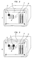
- FIG. 2 shows a screen 21 of a video display monitor 15 of the type used in assembly 11 in FIG. 1.
- FIG. 2 shows a typical appearance of screen 21 when the invention is used in the analysis of a single data object.
- Displayed on screen 21 are one visual attribute icon 23, a physical attribute icon 25, and two separate control panels 27 and 29. Of the latter, control panel 27 is a visual attribute control panel while control panel 29 is a physical attribute control panel.
- visual attribute icon 23 is shown in FIG. 2 as a checkered rectangle. It may, of course, assume any desired form, making use of such specific graphic characteristics or visual attributes as shape, size, color, pattern, or location. It is through such characteristics that visual attribute icon 23 has the ability to display information about some, but not all, of the physical attributes of the data object which can be found in computer memory.
- physical attributes stored in memory may include present location, total capacity of truck, percent of capacity represented by present load, fuel supply, distance from next drop-off point, distance to a proposed new pick-up point, mechanical status of truck, number of hours the driver has been on the road, highway conditions between current location and next drop-off point, driving conditions between next drop-off point and proposed new pick-up point, fuel availability between various drop-off and pick-up points, replacement driver availability, and so on. At least some of these physical attributes may be continually changing with time as up-dated information is supplied to computer memory. In practice, the number of physical attributes considerably exceeds the number of graphic characteristics available to visual attribute icon 23 for its task of providing the operator with visual data.
- Icon 25 differs from icon 23 in that the former displays information about physical attributes in visual graphics from, while the latter identifies all of the physical attributes of the data object residing currently in memory. Such identification may, for example, take the form of a simple listing or, alternatively, a block diagram showing the different physical attributes.
- the smart icon is selected for a "visual attribute" change, its physical attributes are automatically fed into physical attribute control panel 29. Then using the mouse, the operator may select as many of the physical attributes from physical attribute control panel 29 as there are visual attributes to assign.
- the operator uses the mouse on control panels 27 and 29 to assign a visual attribute in the visual attribute icon to each physical attribute selected.
- size may be assigned to the physical attribute total capacity and color may be assigned to the physical attribute fuel supply.
- Additional visual attributes may be assigned and physical attributes selected up to the limits of the number of visual attributes available.
- Physical attribute icon 25 may be displayed selectively on the screen of the video monitor, appearing only, by way of example, when visual attribute icon 23 is clicked upon with the mouse.
- control panels 27 and 29 are also open, as has already been explained.
- Control panel 27, by way of example, displays the available visual attributes of icon 23, while control panel 29 displays the selected data object physical attributes.
- control panel 27 may be given a mark after the listing of the physical attribute size
- control panel 29 may be given a mark after the listing of the physical attribute truck capacity, indicating that size has been assigned to represent truck capacity.
- Other assignments may be similarly indicated.
- lines can be drawn between visual attributes in control panel 27 and selected physical attributes in control panel 29 or the order in which physical attributes appear in control panel 27 can be altered to correspond directly to selected visual attributes in control panel 27.
- Control panels 27 and 29 may, if desired, remain on screen 23 of the video monitor and thus serve to remind the operator of the assignments chosen. Alternatively, they may be presented on the screen only when specified by the operator, either by clicking a mouse or by making an appropriate command line entry.
- the invention gives the operator maximum flexibility
- the mouse is used to select percent of capacity on physical attribute on physical attribute control panel 29 and to select the visual attribute color on visual attribute control panel 27.
- the color of visual attribute icon 23 then shifts as necessary to provide an accurate representation of the physical attribute as it is found in computer memory.
- FIG. 3 shows a video display monitor 15 which is identical with that shown in FIG. 2 with the exception that in FIG. 3 screen 21 contains a second visual attribute icon 31.
- Other icons and control panels in FIG. 3 are the same as in FIG. 2 and bear the same reference numerals.
- Two visual attribute icons 23 and 31 are employed in FIG. 3 to reflect selected physical attributes of two different data objects.
- visual attribute icons 23 and 31 in FIG. 3 may represent two different trucks. They may be grouped together, if desired, in order that their assignments of physical attributes to visual attributes may be identical. Even larger numbers of visual attribute icons may be used if it is necessary to display data relating to larger numbers of data objects.
- the invention is particularly advantageous when used in the simultaneous analysis of multiple data objects. If screen 21 in FIG. 3 is filled with a substantial number of visual attribute icons simultaneously, the operator can tell at a glance just how each data object compared with every other data object displayed with respect to the physical attributes selected. As the operator searches for trends, patterns, or anomalies, the identity of the selected physical attributes can be changed interactively until an answer is found. Since the operator may not have any way of knowing in advance just what sort of an answer is being sought, the "smart objects" on screen 21 are of major assistance in the decision making process.
- Icon 23 may, for example, represent a truck while icon 31 represents a human driver. Now, it would no longer be appropriate for icons 23 and 31 to be members of the same group. Let the visual attributes selected above remain with respect to the truck, but let size now represent the number of hours the driver has been on the road and color represent the driver's wage rate. In other words, the operator wishes to view people differently from the way in which trucks are being viewed.
- the operator may, by way of example, use the mouse to tag one or more data objects (as represented by visual attribute icons) to be included with one set of visual and physical attributes and to tag any other data objects (as represented by visual attribute icons) to be included with another.
- the invention may be readily implemented upon computer assembly 11 in FIG. 1 by one skilled in the art by using object oriented programming techniques.
- object oriented programming techniques The book by Brad J. Cox, "Object Oriented Programming - An Evolutionary Approach,” which was published in 1987 by Addison-Wesley of Reading, Massachusetts, is a standard text on the subject and may be referred to for more detailed information.
- a "smart object" is most easily built from a data object with object-oriented programming tools and appears, in part, as an on-screen icon called a visual attribute icon (e.g., icon 23 in FIG. 2 and icons 23 and 31 in FIG. 3).
- the other parts of a "smart object” include a list of visual attributes (possible visible states), a list of physical attributes (facts about the thing represented), and links to the computer database or databases.
- the visual attribute icon can change its appearance to reflect changes in the underlying data (physical attributes, for example) or user instigated changes.
- the particular appearance or visual attribute that the on-screen object (as represented by the visual attribute icon) assumes is determined interactively by the user.
- the user interactively sets links and transformations between the smart object's physical attributes and the visual attributes displayed.
- the list of visual attributes (in visual attribute control panel 27 in FIGS. 2 and 3) contains a description of each allowable type of variation in appearance that the on-screen visual attribute icon can assume. Examples are color, position, shape, and size. This list is displayed either continually or when the user wants to change the link or links between the visual attributes and the physical attributes.
- the list of physical attributes contains all of the information about the data object (or thing) that is represented by the smart object. This information can be widely varied and may include images, text, or pointers to related information. The user can display this list in the physical attribute icon when needed.
- the smart object visual attribute icon (e.g., icon 23 in FIG. 2 and icons 23 and 31 in FIG. 3) contains links to those databases.
- the first step involves using existing graphical and non-graphical database querying tools to collect existing information related to the data object (or thing) in advance, and allowing the system to query for information during the course of the session on a "need-to-know" basis.
- the second step builds an object that may be called the physical attribute object.
- An attribute of the physical attribute object is a text field.
- the physical attribute object may be hidden or visible on the screen depending on user input (such as clicking with a mouse) to the visual attribute icon.
- the physical attribute object causes a text field to be displayed for conveying information relating to the data object or thing. With respect to the text field, interaction with it (by clicking with a mouse, for example) selects the clicked text entry (a physical attribute). If the data type of the selected entry contains a pointer to another smart object, one method may use the pointer to locate the address of the smart object and creates a new visual attribute icon to represent it. Another method may simply select the indicated text item.
- the visual attributes list is displayed.
- the user may set a link or transformation between the selected physical attribute and a visual attribute. This latter action may be achieved, for example, by what is referred to in the art as a "rubber band" connection, by clicking on a button displayed in a control panel, or by clicking on a visual attribute in the visual attributes list.
- the final action applies the new transformation between the selected physical attribute and the selected visual attribute to the on-screen visual attribute icon.
- the third step is to feed the information from the query in the first step into a list that appears in a text field that is an attribute of the physical attribute object.
- the fourth step is the building of an object that may be called the visual attribute list.
- An attribute of the visual attribute list is a list of all allowable visual states of the associated visual attribute icon. This list may be hidden or visible on the screen depending upon user input to the visual attribute icon (either clicking or double-clicking with a mouse, for example).
- the visual attribute list When the visual attribute list is visible, it displays not only the list of possible visual states, but also any existing links between a visual attribute and a physical attribute pair.
- the fifth step is to designate default states for the visual attributes of the visual attribute icon and the links between entires in the physical attribute list and entries in the visual attribute list.
- the sixth and final step is to build an object on-screen, the visual attribute icon.
- This object should include a prompt to display its physical attributes list and a prompt to display its visual attributes list. It also needs an ability to be selected or deselected as a member of one or more sets of smart objects.
- the membership can be represented internally as an array of variable length, where the value of each entry in the array indicates membership in the set represented by that value, or as a binary value in the array whose value indicates inclusion or exclusion in a set represented by that position in the array.
- Attributes of this object include an associated physical attribute icon, an associated visual attribute list and a wide range of possible visual attributes or graphic appearances. Initially, the visual attribute icon displays the default states determined in step five. Finally, the object needs a list of sets of smart objects of which the smart object is a member. This list varies as a result of the user selecting some new sets and eliminating old ones.
- control panels containing the list of visual attributes and the list of physical attributes, with the existing links and transformations between pairs of visual attributes and physical attributes indicated. If no smart object or set of smart objects has been selected, the control panels may be blank or contain the values of a default smart object. These control panels may be objects with text field attributes where the text fields are the visual or physical attributes of the selected smart object. In the case of selected sets of smart objects, these panels display the sets resulting from the intersection of the physical attribute lists for all of the smart objects in the selected sets, and the intersection of the visual attribute lists for all of the smart objects in the selected set.
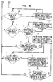
- FIG. 4 shows how FIGS. 4A and 4B combine with one another through paths AA and BB to form a single flow chart.
- step 41 The portion of the flow chart shown in FIG. 4A comprises a set of method steps 41, 43, 45, 47, 49, 51, 53, 55, 57, 59, 61, and 63.
- step 41 The first of these, step 41, is labelled "Start" and represents the beginning of the process performed by the underlying software.
- step 43 opens both a physical attributes control panel and a visual attributes control panel.
- step 45 gives the operator an opportunity to open a smart object based on a data object in one or more of the computer's databases.
- step 45 is a decision step. If the answer is "yes”, the process moves to step 47, where a data object is entered through the computer keyboard, through a control panel button selection, or through some other appropriate input device for representation by a smart object. The next step, step 49, opens a visual attribute icon for the selected data object with visual characteristics at default settings. From that point, the process loops back to step 45 to give the operator an opportunity to open as many additional smart objects as desired. All such additional smart objects would, or course, be based upon data objects contained in one or more of the computer's databases.
- step 51 When the operator has decided that no more smart objects are to be opened, the process moves on to step 51, which offers an opportunity to create a new tagged set of smart objects or modify an old set to receive the next user-designated mapping between physical and visual attributes. If the answer in step 51 is "yes”, the process moves to step 53, which asks if the operator wishes to create a new tagged set. If the answer in step 53 is "yes”, step 55 tags the smart objects to be contained in the new set. If the answer in step 53 is "no”, step 57 asks whether the operator wishes to modify an old tagged set. If the answer in step 57 is "no", the process reverts to step 51 as shown.
- step 59 selects the tagged set for change and step 61 offers an opportunity either to add or to subtract a member.
- step 63 asks whether there are more changes to the selected set. If the answer in step 63 is "yes”, the process loops back to step 61, which offers an opportunity either to add or to subtract another member. If the answer in step 63 is "no”, the process reverts to step 51 as shown. When the answer in step 51 in FIG. 4A is "no", the process moves along path BB to the portion of the flow chart appearing in FIG. 4B.
- step 65 determines from the underlying database whether the values of any of the physical attributes have changed. If they have, the answer is "yes" and the process moves to step 67.
- step 67 the values of the smart object's visual attributes are updated to reflect changes in the values of the physical attributes.
- step 65 If, in step 65, if is determined that none of the values of any of the physical attributes have changed, the answer is "no" and the process moves to step 69. As shown, step 69 makes inquiry to determine whether or not a smart object or set of smart objects has been selected. If the answer in step 69 is "no", the process follows path AA and reverts to step 45 in FIG. 4A to give the operator another opportunity to open a smart object.
- step 69 determines whether the settings of any of the visual attributes have been changed. If they have, the answer is "yes” and the process loops through step 73 which, as needed, updates the values of the smart object's visual attributes to reflect changes in their settings. If the answer is "no", the process moves on to step 75.
- step 75 the process determines whether the smart object's physical attributes icon has been selected by some input device (e.g., by clicking a mouse button). If the answer is "no” the process follows path AA and reverts to step 45 in FIG. 4A, giving the operator yet another opportunity to open a smart object. If the answer in step 75 is "yes”, the process moves to step 77, in which the physical attributes icon associated with the selected smart object is opened and the smart object's physical attributes are listed in a field on the physical attributes icon. From step 77, the process moves to step 79, which determines whether a smart object's physical attributes icon entry has been selected by some input device (e.g., by clicking a mouse button). If the answer in step 79 is "no", the process follows path AA and reverts to step 45 in FIG. 4A to give the operator an opportunity to do so.
- some input device e.g., by clicking a mouse button
- step 81 which records the location of the selection within the field of the physical attributes icon and identifies the physical attribute at the selected location and with the pointer associated with it.
- step 83 determines whether the pointer's value is non-zero. In other words, a determination is made whether a smart object exists corresponding to the object selected in the physical attribute list. If the answer to this final question is "no”, the process reverts to step 45 in FIG. 4A. If the answer in step 83 is "yes”, the process reverts instead to step 77. The operator may, of course, exit from the process at any stage chosen.
- Typical pseudo code which is an example of at least several different possible approaches and permits one skilled in the art of computer programming to practice the implementation of the invention shown in FIGS. 4A and 4B, is attached hereto as an appendix.
Landscapes
- Engineering & Computer Science (AREA)
- General Engineering & Computer Science (AREA)
- Theoretical Computer Science (AREA)
- Human Computer Interaction (AREA)
- Physics & Mathematics (AREA)
- General Physics & Mathematics (AREA)
- User Interface Of Digital Computer (AREA)
- Digital Computer Display Output (AREA)
- Processing Or Creating Images (AREA)
Claims (10)
- Procédé interactif de visualisation d'une pluralité de différents attributs physiques d'au moins un objet de données résidant dans au moins une base de données de la mémoire d'un ordinateur, comprenant les étapes consistant à :générer une icône d'attribut visuel (30) sur l'écran (21) d'un moniteur d'affichage pour l'objet ou chacun des objets de données, l'icône ou les icônes d'attribut visuel affichant des valeurs d'un sous-ensemble desdits attributs physiques en termes de différentes caractéristiques graphiques;générer une icône d'attribut physique (25) pour l'objet ou chacun des objets de données, l'icône ou chaque icône d'attribut physique identifiant tous les attributs de ladite pluralité d'attributs physiques pour l'objet respectif de données;afficher, de façon sélective, ladite ou lesdites icônes d'attribut physique sur l'écran dudit moniteur d'affichage;sélectionner, à partir de l'icône ou de chacune des icônes d'attribut physique, le sous-ensemble de ladite pluralité d'attributs physiques à afficher dans icône respective d'attribut visuel de l'objet respectif de données;assigner, de façon respective, les différentes caractéristiques graphiques dans ladite ou lesdites icônes d'attribut visuel à chaque membre dudit sous-ensemble sélectionné; etafficher des valeurs dudit sous-ensemble sélectionné d'attributs physiques dans ladite ou lesdites icônes d'attribut visuel selon lesdites caractéristiques graphiques assignées.
- Procédé selon la revendication 1, comprenant, de plus, les étapes consistant à :générer au moins un panneau de commande sur l'écran dudit moniteur d'affichage; etafficher dans ledit(lesdits) panneau(x) de commande, à la fois, les attributs physiques individuels constituant ledit sous-ensemble sélectionné et les caractéristiques graphiques dans ladite ou lesdites icônes d'attribut visuel à laquelle elles ont été assignées.
- Procédé selon la revendication 1 ou 2, pour visualiser une pluralité de tels attributs physiques d'une pluralité de tels objets de données.
- Procédé selon la revendication 3, selon lequel au moins certaines desdites icônes d'attribut visuel sont groupées pour afficher des valeurs de ce même sous-ensemble d'attributs sélectionnés à partir des icônes d'attribut physique.
- Dispositif pour faciliter la visualisation d'une pluralité de différents attributs physiques d'au moins un objet de données résidant dans au moins une base de données de la mémoire d'un ordinateur, comprenant :un moyen pour générer une icône d'attribut visuel (30) sur l'écran (21) d'un moniteur d'affichage pour l'objet ou chacun des objets de données, l'icône ou les icônes d'attribut visuel affichant des valeurs d'un sous-ensemble desdits attributs physiques en termes de différentes caractéristiques graphiques;un moyen pour générer une icône d'attribut physique (25) pour l'objet ou chacun desdits objets de données sur l'écran du moniteur d'affichage, l'icône ou chaque icône d'attribut physique identifiant tous les attributs de ladite pluralité d'attributs physiques pour l'objet respectif de données;un moyen pour sélectionner, à partir de l'icône ou de chacune des icônes d'attribut physique, le sous-ensemble de ladite pluralité d'attributs physiques à afficher dans l'icône respective d'attribut visuel;un moyen pour assigner, de façon respective, les différentes caractéristiques graphiques dans ladite ou lesdites icônes d'attribut visuel à chaque membre dudit sous-ensemble sélectionné; etun moyen pour afficher des valeurs dudit sous-ensemble sélectionné d'attributs physiques dans ladite ou lesdites icônes d'attribut visuel selon lesdites caractéristiques graphiques assignées.
- Dispositif selon la revendication 5, comprenant, de plus :un moyen pour générer au moins un panneau de commande sur l'écran dudit moniteur d'affichage; etun moyen pour afficher dans ledit(lesdits) panneau(x) de commande, à la fois, les attributs physiques individuels constituant ledit sous-ensemble sélectionné et les caractéristiques graphiques dans ladite ou lesdites icônes d'attribut visuel à laquelle elles ont été assignées.
- Agencement selon la revendication 5 ou 6, pour faciliter la visualisation d'une pluralité de tels attributs physiques d'une pluralité de tels objets de données.
- Dispositif selon la revendication 7, comprenant, de plus, un moyen pour grouper au moins certaines desdites icônes d'attribut visuel afin d'afficher des valeurs de ce même sous-ensemble d'attributs sélectionnés à partir des icônes d'attribut physique.
- Procédé, système ou dispositif selon l'une quelconque des revendications précédentes, dans lequel lesdites caractéristiques graphiques comprennent la forme et/ou la taille et/ou la couleur et/ou la position et/ou le motif.
- Dispositif selon les revendications 5 à 8, dans lequel ledit dispositif est un système informatique, ledit système informatique comprenant un moniteur d'affichage vidéo et un dispositif d'entrée pour manipuler un pointeur sur l'écran dudit moniteur, ledit dispositif d'entrée étant utilisé pour sélectionner le sous-ensemble de ladite multiplicité d'attributs physiques et pour assigner les différentes caractéristiques graphiques respectives.
Applications Claiming Priority (3)
| Application Number | Priority Date | Filing Date | Title |
|---|---|---|---|
| US07/628,872 US5257349A (en) | 1990-12-18 | 1990-12-18 | Interactive data visualization with smart object |
| US628872 | 1990-12-18 | ||
| PCT/US1991/009166 WO1992011602A1 (fr) | 1990-12-18 | 1991-12-16 | Visualisation de donnees interactives avec un objet intelligent |
Publications (3)
| Publication Number | Publication Date |
|---|---|
| EP0563190A1 EP0563190A1 (fr) | 1993-10-06 |
| EP0563190A4 EP0563190A4 (en) | 1995-11-22 |
| EP0563190B1 true EP0563190B1 (fr) | 1998-11-18 |
Family
ID=24520660
Family Applications (1)
| Application Number | Title | Priority Date | Filing Date |
|---|---|---|---|
| EP92901808A Expired - Lifetime EP0563190B1 (fr) | 1990-12-18 | 1991-12-16 | Visualisation de donnees interactive |
Country Status (5)
| Country | Link |
|---|---|
| US (1) | US5257349A (fr) |
| EP (1) | EP0563190B1 (fr) |
| JP (1) | JP3656220B2 (fr) |
| DE (1) | DE69130509T2 (fr) |
| WO (1) | WO1992011602A1 (fr) |
Families Citing this family (43)
| Publication number | Priority date | Publication date | Assignee | Title |
|---|---|---|---|---|
| US5761655A (en) * | 1990-06-06 | 1998-06-02 | Alphatronix, Inc. | Image file storage and retrieval system |
| US6384847B1 (en) * | 1992-03-20 | 2002-05-07 | International Business Machines Corporation | Interactive graphical method for analyzing many-dimensional data sets |
| US5689663A (en) * | 1992-06-19 | 1997-11-18 | Microsoft Corporation | Remote controller user interface and methods relating thereto |
| US5345543A (en) * | 1992-11-16 | 1994-09-06 | Apple Computer, Inc. | Method for manipulating objects on a computer display |
| US5450540A (en) * | 1992-12-16 | 1995-09-12 | Apple Computer, Inc. | Graphical interface for interacting constrained actors |
| US5414809A (en) * | 1993-04-30 | 1995-05-09 | Texas Instruments Incorporated | Graphical display of data |
| JPH06325140A (ja) * | 1993-05-18 | 1994-11-25 | Fujitsu Ltd | 表示属性のグループ化により表示処理を簡易化した図形表示処理方式 |
| JP3083676B2 (ja) * | 1993-05-21 | 2000-09-04 | 株式会社日立製作所 | デ−タファイル装置 |
| US5594858A (en) * | 1993-07-29 | 1997-01-14 | Fisher-Rosemount Systems, Inc. | Uniform control template generating system and method for process control programming |
| US5632009A (en) * | 1993-09-17 | 1997-05-20 | Xerox Corporation | Method and system for producing a table image showing indirect data representations |
| JP3150246B2 (ja) * | 1993-12-09 | 2001-03-26 | キヤノン株式会社 | データ管理方法及び装置 |
| KR960008583A (ko) * | 1994-08-26 | 1996-03-22 | 윌리암 티. 엘리스 | 데이타 프로세싱 시스템 및 데이타 프로세싱 시스템 관리 방법 |
| US5680530A (en) * | 1994-09-19 | 1997-10-21 | Lucent Technologies Inc. | Graphical environment for interactively specifying a target system |
| US5946678A (en) * | 1995-01-11 | 1999-08-31 | Philips Electronics North America Corporation | User interface for document retrieval |
| US5548692A (en) * | 1995-02-21 | 1996-08-20 | Eastman Kodak Company | Method for layout of arbitrarily sized and shaped icons in a display |
| US6034676A (en) * | 1995-04-11 | 2000-03-07 | Data View, Inc. | System and method for measuring and processing tire depth data |
| US5657460A (en) * | 1995-04-11 | 1997-08-12 | Data View, Inc. | System and method for storing and displaying data |
| US6003037A (en) * | 1995-11-14 | 1999-12-14 | Progress Software Corporation | Smart objects for development of object oriented software |
| US6337699B1 (en) * | 1996-06-27 | 2002-01-08 | Sun Microsystems, Inc. | Visualizing degrees of information object attributes |
| US5974201A (en) * | 1996-10-01 | 1999-10-26 | Siemens Corporate Research, Inc. | Smart image system |
| US6070169A (en) * | 1998-02-12 | 2000-05-30 | International Business Machines Corporation | Method and system for the determination of a particular data object utilizing attributes associated with the object |
| US6522325B1 (en) | 1998-04-02 | 2003-02-18 | Kewazinga Corp. | Navigable telepresence method and system utilizing an array of cameras |
| CN1298607A (zh) | 1998-04-02 | 2001-06-06 | 凯瓦津格公司 | 采用摄像机阵列的可巡视远程出席方法及系统 |
| JP3752867B2 (ja) * | 1998-11-04 | 2006-03-08 | 富士ゼロックス株式会社 | ドキュメント処理装置 |
| US6442589B1 (en) | 1999-01-14 | 2002-08-27 | Fujitsu Limited | Method and system for sorting and forwarding electronic messages and other data |
| US6462763B1 (en) | 1999-08-24 | 2002-10-08 | Spotware Technologies, Inc. | Method, system, and software for tracking moving hotspots with a static or moving cursor |
| US6559871B1 (en) | 1999-09-29 | 2003-05-06 | International Business Machines Corporation | Asynchronous tree navigator graphical user interface and associated methods |
| US7106329B1 (en) | 1999-09-30 | 2006-09-12 | Battelle Memorial Institute | Methods and apparatus for displaying disparate types of information using an interactive surface map |
| US6990238B1 (en) * | 1999-09-30 | 2006-01-24 | Battelle Memorial Institute | Data processing, analysis, and visualization system for use with disparate data types |
| US7134095B1 (en) | 1999-10-20 | 2006-11-07 | Gateway, Inc. | Simulated three-dimensional navigational menu system |
| US6822650B1 (en) * | 2000-06-19 | 2004-11-23 | Microsoft Corporation | Formatting object for modifying the visual attributes of visual objects to reflect data values |
| US20020129342A1 (en) * | 2001-03-07 | 2002-09-12 | David Kil | Data mining apparatus and method with user interface based ground-truth tool and user algorithms |
| WO2005062201A1 (fr) * | 2003-12-22 | 2005-07-07 | John Thomas Magnifico | Systeme de visualisation superieure (tvs) |
| US20050174337A1 (en) * | 2004-02-11 | 2005-08-11 | Nielsen Paul S. | Electronic handheld drawing and gaming system using television monitor |
| DE102010048810A1 (de) | 2010-10-20 | 2012-04-26 | Hüttinger Elektronik Gmbh + Co. Kg | System zur Bedienung mehrerer Plasma- und/oder Induktionserwärmungsprozesse |
| DE102010048809A1 (de) | 2010-10-20 | 2012-04-26 | Hüttinger Elektronik Gmbh + Co. Kg | Leistungsversorgungssystem für eine Plasmaanwendung und/oder eine Induktionserwärmungsanwendung |
| US8823711B2 (en) | 2010-12-17 | 2014-09-02 | Microsoft Corporation | Incremental creation of a graphical object to visually represent a data set |
| US20140156327A1 (en) * | 2012-12-04 | 2014-06-05 | Sap Ag | Collaborative job dispatching systems and methods |
| EP3182304A1 (fr) | 2013-03-29 | 2017-06-21 | Pilab S.A. | Procédé mis en uvre par ordinateur destiné à mémoriser une quantité illimitée de données sous forme d'une carte conceptuelle dans des systèmes de bases de données relationnelles |
| EP3159815A1 (fr) | 2013-06-30 | 2017-04-26 | Pilab S.A. | Exploration de données non hiérarchisée de base de données |
| EP2843567B1 (fr) | 2013-08-30 | 2017-05-10 | Pilab S.A. | Procédé informatique pour améliorer l'exécution de requête dans les bases de données relationnelles normalisées au niveau 4 et supérieur |
| EP2843568A1 (fr) | 2013-08-30 | 2015-03-04 | Pilab S.A. | Procédé informatique permettant de créer des structures de base de données sans connaissance sur le fonctionnement du système de base de données relationnelle |
| WO2017186774A1 (fr) | 2016-04-26 | 2017-11-02 | Pilab S.A. | Systèmes et procédés d'interrogation de bases de données |
Family Cites Families (11)
| Publication number | Priority date | Publication date | Assignee | Title |
|---|---|---|---|---|
| US4813013A (en) * | 1984-03-01 | 1989-03-14 | The Cadware Group, Ltd. | Schematic diagram generating system using library of general purpose interactively selectable graphic primitives to create special applications icons |
| US4649499A (en) * | 1984-03-07 | 1987-03-10 | Hewlett-Packard Company | Touchscreen two-dimensional emulation of three-dimensional objects |
| US4901221A (en) * | 1986-04-14 | 1990-02-13 | National Instruments, Inc. | Graphical system for modelling a process and associated method |
| GB2191918B (en) * | 1986-06-16 | 1990-09-05 | Ibm | Data display system |
| SE8603442L (sv) * | 1986-08-15 | 1988-02-16 | Ibm Svenska Ab | Metod for bildskermspanelbehandling |
| GB8621061D0 (en) * | 1986-09-01 | 1986-10-08 | Hewlett Packard Ltd | User interface simulation |
| US4811240A (en) * | 1986-12-22 | 1989-03-07 | International Business Machines Corporation | System for creating and controlling interactive graphic display screens |
| US5072412A (en) * | 1987-03-25 | 1991-12-10 | Xerox Corporation | User interface with multiple workspaces for sharing display system objects |
| US5081592A (en) * | 1987-08-05 | 1992-01-14 | Tektronix, Inc. | Test system for acquiring, calculating and displaying representations of data sequences |
| JP2516387Y2 (ja) * | 1987-08-19 | 1996-11-06 | 三洋電機株式会社 | 情報ファイル装置 |
| US5041992A (en) * | 1988-10-24 | 1991-08-20 | University Of Pittsburgh | Interactive method of developing software interfaces |
-
1990
- 1990-12-18 US US07/628,872 patent/US5257349A/en not_active Expired - Lifetime
-
1991
- 1991-12-16 JP JP50199892A patent/JP3656220B2/ja not_active Expired - Lifetime
- 1991-12-16 EP EP92901808A patent/EP0563190B1/fr not_active Expired - Lifetime
- 1991-12-16 DE DE69130509T patent/DE69130509T2/de not_active Expired - Fee Related
- 1991-12-16 WO PCT/US1991/009166 patent/WO1992011602A1/fr not_active Ceased
Also Published As
| Publication number | Publication date |
|---|---|
| EP0563190A1 (fr) | 1993-10-06 |
| WO1992011602A1 (fr) | 1992-07-09 |
| DE69130509D1 (de) | 1998-12-24 |
| DE69130509T2 (de) | 1999-04-22 |
| EP0563190A4 (en) | 1995-11-22 |
| JPH06503667A (ja) | 1994-04-21 |
| US5257349A (en) | 1993-10-26 |
| JP3656220B2 (ja) | 2005-06-08 |
Similar Documents
| Publication | Publication Date | Title |
|---|---|---|
| US5257349A (en) | Interactive data visualization with smart object | |
| US11663230B2 (en) | Interface including graphic representation of relationships between search results | |
| US6075536A (en) | Information visualizing system | |
| US6055515A (en) | Enhanced tree control system for navigating lattices data structures and displaying configurable lattice-node labels | |
| US5894311A (en) | Computer-based visual data evaluation | |
| US6707454B1 (en) | Systems and methods for visualizing multi-dimensional data in spreadsheets and other data structures | |
| US5742777A (en) | Apparatus for selective simultaneous display of information about plurality of entities | |
| US6216139B1 (en) | Integrated dialog box for rapidly altering presentation of parametric text data objects on a computer display | |
| US6693651B2 (en) | Customer self service iconic interface for resource search results display and selection | |
| US6778193B2 (en) | Customer self service iconic interface for portal entry and search specification | |
| US5390296A (en) | Method and apparatus for calculation with display data | |
| US6240395B1 (en) | Device and method for project management | |
| US5278751A (en) | Dynamic manufacturing process control | |
| KR101794373B1 (ko) | 선택된 데이터의 일시적인 포맷팅 및 도표화 기법 | |
| US7158992B2 (en) | Method for comparative visual rendering of data | |
| US7287233B2 (en) | Minimization function for a computer user interface | |
| US7719534B2 (en) | Object association in a computer generated drawing environment | |
| US5805171A (en) | Technical schematic display system utilizing preassigned component detail levels | |
| EP0697667A1 (fr) | Procédé et dispositif d'affichage de structures et relations d'une base de données relationelle | |
| JPH07134765A (ja) | データのグラフ表示の方法 | |
| US5896491A (en) | System and method for executing functions associated with function icons | |
| EP0558223B1 (fr) | Système de gestion de fenêtres dans une station de travail d'ordinateur | |
| JPH09325878A (ja) | メニュー選択装置 | |
| GB2394154A (en) | Presenting information by displaying a list of items and attributes | |
| JPH08305617A (ja) | ファイル表示システム及びファイル表示方法 |
Legal Events
| Date | Code | Title | Description |
|---|---|---|---|
| PUAI | Public reference made under article 153(3) epc to a published international application that has entered the european phase |
Free format text: ORIGINAL CODE: 0009012 |
|
| 17P | Request for examination filed |
Effective date: 19930609 |
|
| AK | Designated contracting states |
Kind code of ref document: A1 Designated state(s): DE FR GB |
|
| A4 | Supplementary search report drawn up and despatched | ||
| AK | Designated contracting states |
Kind code of ref document: A4 Designated state(s): DE FR GB |
|
| 17Q | First examination report despatched |
Effective date: 19970207 |
|
| RAP1 | Party data changed (applicant data changed or rights of an application transferred) |
Owner name: SARNOFF CORPORATION |
|
| GRAG | Despatch of communication of intention to grant |
Free format text: ORIGINAL CODE: EPIDOS AGRA |
|
| GRAG | Despatch of communication of intention to grant |
Free format text: ORIGINAL CODE: EPIDOS AGRA |
|
| GRAH | Despatch of communication of intention to grant a patent |
Free format text: ORIGINAL CODE: EPIDOS IGRA |
|
| GRAH | Despatch of communication of intention to grant a patent |
Free format text: ORIGINAL CODE: EPIDOS IGRA |
|
| GRAA | (expected) grant |
Free format text: ORIGINAL CODE: 0009210 |
|
| AK | Designated contracting states |
Kind code of ref document: B1 Designated state(s): DE FR GB |
|
| REF | Corresponds to: |
Ref document number: 69130509 Country of ref document: DE Date of ref document: 19981224 |
|
| ET | Fr: translation filed | ||
| PLBE | No opposition filed within time limit |
Free format text: ORIGINAL CODE: 0009261 |
|
| STAA | Information on the status of an ep patent application or granted ep patent |
Free format text: STATUS: NO OPPOSITION FILED WITHIN TIME LIMIT |
|
| 26N | No opposition filed | ||
| REG | Reference to a national code |
Ref country code: GB Ref legal event code: IF02 |
|
| PGFP | Annual fee paid to national office [announced via postgrant information from national office to epo] |
Ref country code: DE Payment date: 20090202 Year of fee payment: 18 |
|
| PGFP | Annual fee paid to national office [announced via postgrant information from national office to epo] |
Ref country code: GB Payment date: 20081229 Year of fee payment: 18 |
|
| PGFP | Annual fee paid to national office [announced via postgrant information from national office to epo] |
Ref country code: FR Payment date: 20081217 Year of fee payment: 18 |
|
| GBPC | Gb: european patent ceased through non-payment of renewal fee |
Effective date: 20091216 |
|
| REG | Reference to a national code |
Ref country code: FR Ref legal event code: ST Effective date: 20100831 |
|
| PG25 | Lapsed in a contracting state [announced via postgrant information from national office to epo] |
Ref country code: FR Free format text: LAPSE BECAUSE OF NON-PAYMENT OF DUE FEES Effective date: 20091231 |
|
| PG25 | Lapsed in a contracting state [announced via postgrant information from national office to epo] |
Ref country code: DE Free format text: LAPSE BECAUSE OF NON-PAYMENT OF DUE FEES Effective date: 20100701 |
|
| PG25 | Lapsed in a contracting state [announced via postgrant information from national office to epo] |
Ref country code: GB Free format text: LAPSE BECAUSE OF NON-PAYMENT OF DUE FEES Effective date: 20091216 |