EP0563436B1 - Bâtiment transportable et sa méthode de construction - Google Patents
Bâtiment transportable et sa méthode de construction Download PDFInfo
- Publication number
- EP0563436B1 EP0563436B1 EP92114192A EP92114192A EP0563436B1 EP 0563436 B1 EP0563436 B1 EP 0563436B1 EP 92114192 A EP92114192 A EP 92114192A EP 92114192 A EP92114192 A EP 92114192A EP 0563436 B1 EP0563436 B1 EP 0563436B1
- Authority
- EP
- European Patent Office
- Prior art keywords
- cell according
- wall
- profile section
- frame
- door
- Prior art date
- Legal status (The legal status is an assumption and is not a legal conclusion. Google has not performed a legal analysis and makes no representation as to the accuracy of the status listed.)
- Expired - Lifetime
Links
Images


Classifications
-
- H—ELECTRICITY
- H02—GENERATION; CONVERSION OR DISTRIBUTION OF ELECTRIC POWER
- H02B—BOARDS, SUBSTATIONS OR SWITCHING ARRANGEMENTS FOR THE SUPPLY OR DISTRIBUTION OF ELECTRIC POWER
- H02B7/00—Enclosed substations, e.g. compact substations
- H02B7/06—Distribution substations, e.g. for urban network
-
- E—FIXED CONSTRUCTIONS
- E04—BUILDING
- E04H—BUILDINGS OR LIKE STRUCTURES FOR PARTICULAR PURPOSES; SWIMMING OR SPLASH BATHS OR POOLS; MASTS; FENCING; TENTS OR CANOPIES, IN GENERAL
- E04H5/00—Buildings or groups of buildings for industrial or agricultural purposes
- E04H5/02—Buildings or groups of buildings for industrial purposes, e.g. for power-plants or factories
- E04H5/04—Transformer houses; Substations or switchgear houses
-
- E—FIXED CONSTRUCTIONS
- E06—DOORS, WINDOWS, SHUTTERS, OR ROLLER BLINDS IN GENERAL; LADDERS
- E06B—FIXED OR MOVABLE CLOSURES FOR OPENINGS IN BUILDINGS, VEHICLES, FENCES OR LIKE ENCLOSURES IN GENERAL, e.g. DOORS, WINDOWS, BLINDS, GATES
- E06B7/00—Special arrangements or measures in connection with doors or windows
- E06B7/02—Special arrangements or measures in connection with doors or windows for providing ventilation, e.g. through double windows; Arrangement of ventilation roses
- E06B7/08—Louvre doors, windows or grilles
- E06B7/082—Louvre doors, windows or grilles with rigid or slidable lamellae
-
- E—FIXED CONSTRUCTIONS
- E06—DOORS, WINDOWS, SHUTTERS, OR ROLLER BLINDS IN GENERAL; LADDERS
- E06B—FIXED OR MOVABLE CLOSURES FOR OPENINGS IN BUILDINGS, VEHICLES, FENCES OR LIKE ENCLOSURES IN GENERAL, e.g. DOORS, WINDOWS, BLINDS, GATES
- E06B7/00—Special arrangements or measures in connection with doors or windows
- E06B7/14—Measures for draining-off condensed water or water leaking-in frame members for draining off condensation water, throats at the bottom of a sash
-
- H—ELECTRICITY
- H02—GENERATION; CONVERSION OR DISTRIBUTION OF ELECTRIC POWER
- H02B—BOARDS, SUBSTATIONS OR SWITCHING ARRANGEMENTS FOR THE SUPPLY OR DISTRIBUTION OF ELECTRIC POWER
- H02B1/00—Frameworks, boards, panels, desks, casings; Details of substations or switching arrangements
- H02B1/56—Cooling; Ventilation
Definitions
- the invention relates to a transportable room cell according to the preamble of claim 1.
- the invention also relates to a method for producing this room cell.
- the line interior of a transformer station of this type is divided into a transformer compartment for receiving the transformer with an oil pan underneath, and a switch compartment for receiving the high, medium or low voltage switching devices.
- Such stations are factory-equipped with the necessary switching devices - assuming the transformer -, mounting rails and the complete electrical installation including earthing, so that at the construction site only the transformer, usually mounted on wheels, is mounted on rails in the station must be inserted into the interior of the cell.
- the latter is accessible thanks to two horizontally pivoting doors that are part of a side wall made of profiles and panels.
- DE-GM 83 34 221 it was proposed for simplification to design a pair of concrete ribs as rails for the transformer of the substation and a third - also molded onto the floor slab and to be provided as part of the oil pan compared to the other two taller concrete ribs.
- a fourth integrally formed rib serves here as a support for floor panels, in particular in the part of the transformer station which has the control cabinets, and can itself have different heights in adaptation to the different floor heights.
- a room cell is known as an electrical network station, which has lower side walls and an intermediate floor resting on the lower side walls.
- An intermediate wall extends from the intermediate floor as a pressure sign, which is drawn a predetermined distance into the interior of the network station and is guided just under the roof of the station.
- the inventor has set itself the goal of producing, equipping and using such a small station in a simple and inexpensive manner.
- the adaptability to different types of electrical installation elements is to be facilitated.
- two side walls of a height corresponding to the room cell and end walls connecting these side walls and floor ribs approximately parallel thereto are monolithically formed on the base plate; the bottom ribs form with the side walls a floor pan for the transformer room and in each case a base for an intermediate wall or wall plate that can be retrofitted onto it - delimiting the transformer room between the side walls.
- the end wall consists in its upper region of the lock door, d. H. only the lower wall area is cast in a monolithic way, up to a contour line specifying the installation depth of the switchover station.
- the contour of the upper edges of the end walls advantageously also determines the position of the threshold edge of the fan door (s), and furthermore the minimum height of the bottom rib adjoining the low-voltage space; the low-voltage room should be open at the lower end of its front wall for better cable assembly, which is why the height of the monolithic oil pan on this side is particularly important. This does not apply to the other bottom rib to the same extent, since the medium-voltage space, according to the invention, in turn offers a closed, watertight floor pan.
- the intermediate walls or wall plates to be subsequently attached and fixed on the base ribs are well suited to holding holding profiles, fastening screws and the like for fixing the medium-voltage or low-voltage system, and openings for carrying out the connecting lines between the systems and the transformer.
- these wall plates can offer different openings and fastening options; the adaptation of the room cell is thus reduced to the design of these partition walls.
- the removable partitions can have concreted weld-on plates with which they are thermally fastened to welded-on plates also concreted in the concrete body will.
- partition walls it has proven to be expedient to design such partition walls on their left and right delimitation sides so that the partition wall, which is preferably recessed into grooves in the conical structure, can adapt to this.
- the building structure according to the invention can have recesses in the area of all required door frames with specially profiled and reinforced concrete parts reinforced by concreted metal parts, into which a special frame profile for single and double-leaf doors and fan doors can be inserted from above.
- At least one earth connection - advantageously a continuous so-called HZA anchor rail - should be concreted in at least one side wall inside the cell, and an empty pipe on the opposite side wall.
- This has outlet boxes in each room, so that the lighting body of LV, MV and transformer room can be connected to each other and operated with a single switch.
- the intermediate wall provided between the medium-voltage space and the transformer space should have a wide base recess for a cooling grill made of several layers of expanded metal or the like.
- the trough-like bottom area of the transformer room is lined with a second trough made of metal, plastic or another material, which can advantageously be concreted into the space cell during manufacture.
- the frame of the fan door (s) or the lock door (s), which is preferably designed as a light extruded profile into the side walls of the room cell, so that a separate fixing can be omitted.
- the cross section of such an extruded profile consists, for example, of a channel profile facing the door with molding webs on the outside which engage as an anchor in the concrete body.
- one of these shaping webs forms, with an intermediate piece and a profile hook of the frame profile, an outwardly opening channel space.
- the structure below the door to the medium-voltage room has a removable door sill and a removable front panel (fiber cement panel), which can be sealed surface-tight using appropriate devices; the removable plate and the removable door sill make it easier to install the cable terminations on the medium-voltage system.
- This construction is made possible with the same castable frame profiles, which serve as a frame for the fan door or the lock door.
- the threshold part of the frame formed by the frame profile sections is releasably fixed on a stationary cross profile, for example an angular profile cast at both ends, which runs at a distance from the threshold edge of the side wall recess or to the upper edge of the front wall.
- the frame of the fan door is a cross-sectionally approximately H-shaped profile strip, the outer side leg of which rests on the frame profile with a sealing lip and the inner leg surrounds parallel slats.
- a perforated plate or the like should run on the fan door behind the slats.
- the described substation or small station can be produced very economically by means of a new production process, since the shape, in particular the core compared to shrinkable cores, requires less investment and, moreover, the bodies can be produced in stock; the individual design features per body, which are bound to the respective switch products, are reduced according to the invention to the separated sections of the partition walls.
- transformer stations adapted to the respective switch brands can be quickly delivered; A body and a roof panel are removed from the finished parts store and only the individual partition wall parts still to be produced are produced and installed. Throughput times and delivery times for functionally correct compact stations are thus significantly reduced.
- an oil pan can be produced without a construction joint and the principle of concern of the Water Resources Act can be met, whereby at the same time concrete frames or inserted door frames are used, which represent a high-strength construction with the entire honeycomb and box-shaped substructure and the roof panel screwed on with four strong angles.
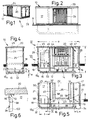
- a cuboid, non-accessible changeover or small station 10 - for example, a length a here of about 3,600 mm, a width b of 1,550 mm and an external height h of 2,200 mm - for receiving a transformer 14 which can be moved on rollers 12 has side walls 17 formed on a base plate 16 and two end walls 18, 19 connecting them in their lower region.
- the side walls 17 carry an attached roof panel 20.
- each of the side walls 17 there is a recess 22 for a fan door 24, the frame 26 of which is cast into the side wall 17.
- the threshold edge 23 of the recess 22 runs at a distance h1 of approximately 800 mm from the base plate 16 of thickness e of 100 mm. This threshold edge 23 is aligned with the upper edges 21 of the two end walls 18, 19 and at the same time determines the operating depth of the switching station 10; this is embedded in grown soil in such a way that the ground level or surface B is slightly below the threshold edge 23 or top edge 21.
- locking doors 28 Between the upper edges 21 of the end walls 18, 19 and the roof plate 20 there are locking doors 28, the frames 30 of which are also cast into the body of the small station 10. These locking doors 28 can - as indicated in particular in FIG. 8 - be made with one or two leaves.
- the end wall 18 of the small station 10 on the left in FIG. 3 is inclined in its area 18a adjoining the base plate 16 at an angle of approximately 45 ° and is provided there with two openings 32 for the passage of cables.
- the other end wall 19 consists of a concrete strip which extends between the side walls 17 and which, with the bottom plate 16 running at a distance from it, delimits a bottom slot 34 at the corresponding lower corner of the body of the switching station 10.
- the base plate 16 delimits that base slot 34 with a bevelled edge in order to prevent damage in the case of cables pushed through here.
- a bottom rib 36 of height i of 300 mm is formed out of the base plate 16, which tapers conically upwards as well as a second bottom rib 38, the distance f1 of which from the nearest end wall 19 only 400 mm measures, but its height i1 is 630 mm.
- the floor area 16, 17, 18, 18 a, 36 of the medium-voltage space 45 is a sealed trough thanks to the sealing cable bushings in the openings 32, which are indicated in FIG. 8.
- Both bottom ribs 36, 38 are sections of intermediate walls - namely base sleepers for wall panels 40, 42 placed on their upper edges 37 - which divide the interior of the small station 10 into a transformer room 44 for the transformer 14, one - in Fig. 5 on the left - Medium-voltage compartment 45 and a low-voltage compartment 47 arranged on the other side of the transformer compartment 44 and narrower in longitudinal section for receiving corresponding MV or LV switching devices 46 and 48, respectively.
- the usable partition walls or wall plates 40, 42 allow simple adaptation of the room cell 10 to different designs of the switching devices 46, 48 and contain welding plates with which they are thermally connected to corresponding welding plates of the side walls 17.
- the intermediate walls 40, 42 are - not shown - designed trapezoidal on their longitudinal edges in order to adapt to the conical structure. Grooves for countersinking the wall plates 40, 42 are provided in this.
- a base recess 50 is made in its lower region according to FIG. 15, to which a recess 52 is assigned on one flank to form a shoulder shoulder 51 as a cable passage and dowels 54 on both sides.
- the latter act as bolts when inserting the MV partition 40 - corresponding to the LV partition 42 with counter-elements 56 in the bottom ribs 36, 38 together as connecting members.
- the entire length of the LV partition 42 rests on its base section 38 and is equipped on its side facing the low-voltage space 47 with fastening rails 58 for the installation of installations. That recess 50 with a dimension of approximately 900 x 300 mm accommodates a corresponding angle frame 60, on which five layers of expanded metal are fixed as cooling grids by means of a ladder-like flat steel frame 62.
- the concrete body 16 to 19 described is cast monolithically in the position shown in FIG. 11 - with the base plate 20 lying on top, the frames 26, 30 being cast in simultaneously. Also in this operation, the fastening rails 58, a horizontally continuous - in FIG. 5 the top edge 37 of the bottom rib 36 approximately touching - grounding rail 59 are introduced, and at 55 indicated flush pipes for installation lines.
- 18 to 20 show a unit 64 consisting of a two-leaf lock door 28 and a removable front plate 66 made of eternit, asbestos or the like.
- the frame 30a of this unit 64 not only covers the locking door 28, but also the front plate 66 and offers a frame profile 70 extruded from an aluminum alloy. This is assigned to the side or end walls 17 and 18 and - as already mentioned - poured into them. It forms an overall U-shaped frame, which is complemented by a gutter profile 72 of another design towards the roof panel 20.
- the cross section of the channel profile 72 consists of two legs 74, 75 which are at right angles to one another and which are separated by a - An angle of about 45 ° to each of the legs 74,75 - inclined intermediate piece 76 are connected.
- the longer extension leg 74 assigned to that roof panel 20 is equipped with a shaped rib 77 running parallel to the other leg 75, the vertical other leg 75 in the installed position merges at its free end into an angular section 78.
- a short shaped web 79 is formed on the spacer 76 at a short distance from it, which delimits an insertion slot 80 with the angular section 78.
- the frame profile 70 corresponds to i. w. the channel profile 72, but on the outer surface of the longer leg 74 opposite the shaped rib 77 has two mutually parallel molding webs 82, 83 which are directed parallel to the shaped rib 77.
- the molded web 83 present in the installed position on the outside of the door attaches to the inner part of the oblique intermediate piece 76 and, together with this and a profile hook 84 which projects horizontally in this installed position, forms a channel space 86 which opens conically towards the outside.
- FIG. 19 in the intermediate piece 76, which runs approximately horizontally in the middle of the figure, a drainage hole 87 can be seen, from which dripping water reaches the outer surface of the profile hook 84 serving as a drainage surface.
- Fig. 19 also shows that the frame section offering the drainage hole 87 is removably screwed onto a fixed angle profit as a crossbar 90 or the like.
- Fastening means which forms the upper boundary of the lower field for the front plate 66, which between the described upper frame profile 70 and a similarly shaped lower frame profile 70 is fixed, the latter is concreted into the end wall 18, 19, specifically by means of the molding webs 82, 83, the cross section of which is surrounded on three sides by the concrete.
- 92 designates a hose seal for the front plate 66, 94 a weatherstrip of the channel profile 72 and 96 an only indicated sealing lip of the closing door 28.
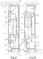
- FIGS. 21 and 22 use the frame or channel profiles 70 and 72 described and differ in the different designs of the profiles which form the fan door 24.
- box profiles 98 can be seen as a frame for a door insert, which consists of an almost S-shaped double bracket 100 in cross section.
- the cross sections of the upper and lower double angles 100 are aligned with one another. Between these, vertical slats 114, which are approximately S-shaped in cross section according to FIG. 10, and a perforated plate 102 lying behind them can be seen.
- the lower double angle 100t in FIG. 21 has an integrally formed channel 101 as a water trap. In another version, the lower double angle can instead be 100 t longer and thus form the water catchment.
- the door leaf 102 is attached between two profile strips 104 of approximately H-shaped cross section, each with an inner leg 106 projecting toward the door leaf 102 and an outer leg 107, which are arranged in opposite directions with mutually directed inner legs 106.
- the two legs 106, 107 protrude from a horizontal cross-sectional strip 108 and the outer leg 107 carries the sealing lip 96 mentioned.
- the cross-sectional strip 108 forms, with the molded-on hook ribs 109, an insertion path 110, for example for sealing members (not shown) or corner pieces (not shown) which hold the individual frame sections together.
- FIGS. 9 and 10 which — also concreted in — show frame profiles 70 in which hinges 112 are stored.
- the box section 98 for the vertically extending slats 114 is seated on them as the frame of the fan door 24.
- two adjacent and parallel slats 114 each delimit a meandering air path which is protected against access from outside.
- the drawing does not show that an inner tub made of steel, plastic or other material is concreted into the floor area during the manufacturing process in the transformer or transformer room 44.
Landscapes
- Engineering & Computer Science (AREA)
- Power Engineering (AREA)
- Architecture (AREA)
- Civil Engineering (AREA)
- Structural Engineering (AREA)
- Building Environments (AREA)
- Specific Sealing Or Ventilating Devices For Doors And Windows (AREA)
- Load-Bearing And Curtain Walls (AREA)
- External Artificial Organs (AREA)
- Moulds, Cores, Or Mandrels (AREA)
- Battery Mounting, Suspending (AREA)
- Hybrid Cells (AREA)
- Photovoltaic Devices (AREA)
- Immobilizing And Processing Of Enzymes And Microorganisms (AREA)
- Physical Deposition Of Substances That Are Components Of Semiconductor Devices (AREA)
Claims (15)
- Cellule transportable sous la forme d'une sous-station de transformation enfoncée partiellement dans le sol, comportant un espace de transformation pour un transformateur ou similaire, comportant au moins une paroi latérale coulée sur une plaque de fond et une plaque de toit posée sur celle-ci, des nervures en béton se rétrécissant transversalement en s'éloignant de la plaque de fond, étant formées sur la plaque de fond, en faisant saillie dans l'espace intérieur de la cellule, caractérisée en ce que
deux parois latérales (17) de la hauteur (h) de la cellule (10) ainsi que des parois frontales (18, 19) reliant celles-ci et des nervures de fond (36, 38) sensiblement parallèles sont formées de manière monolithique sur la plaque de fond (16), en ce que les nervures de fond forment avec les parois latérales une cuve au sol pour l'espace de transformation (44) ainsi qu'à chaque fois un socle pour une paroi intermédiaire ou plaque formant paroi (40, 42), pouvant être montée ultérieurement, et délimitant l'espace de transformation entre les parois latérales (17). - Cellule suivant la revendication 1, caractérisée en ce que la paroi frontale (18, 19) présente une porte obturatrice (28) pour un espace de moyenne tension (45) ou un espace de basse tension (47), l'arête supérieure (21) de la paroi frontale (18, 19) s'étendant le cas échéant sensiblement sur la hauteur de l'arête supérieure (37) de l'une des nervures de fond (38) et la porte obturatrice (28) s'étendant entre l'arête supérieure de la paroi et les parois latérales (17).
- Cellule suivant la revendication 1 ou 2, caractérisée en ce qu'un creux (22) est prévu dans au moins une paroi latérale de l'espace de transformation pour une porte de ventilateur (24) associée à un châssis, ou pour un élément d'obturation mobile similaire, en ce qu'une arête de seuil (23) du creux (22) prévu pour la porte de ventilateur (24) affleure sensiblement avec l'arête supérieure (37) de la nervure de fond (38) associée à l'espace de faible tension (47) et/ou en ce que l'arête supérieure (21) des parois frontales (18, 19) définit la profondeur de montage de la cellule (10).
- Cellule suivant l'une des revendications 1 à 3, caractérisée en ce que le secteur de fond de la zone de moyenne tension (45) est réalisé sous la forme d'une cuve étanche et est muni d'au moins un passage étanche de câble et/ou en ce que l'espace de transformation (44) comporte une cuve intérieure étanche qui est moulée en particulier dans la cellule (10).
- Cellule suivant l'une des revendications 1 à 4, caractérisée en ce qu'au moins une barre de terre (59) s'étend au-dessus de l'arête supérieure (37) de la nervure de fond (36), sur le secteur de la cuve étanche de la zone de moyenne tension et la zone de basse tension, barre qui s'étend sensiblement horizontalement sur une paroi latérale (17).
- Cellule suivant au moins l'une des revendications 1 à 5, caractérisée en ce que la plaque formant paroi ou la paroi intermédiaire (40, 42) amovible est réalisée de manière à pouvoir être insérée dans des rainures des deux parois latérales (17) et/ou en ce que la plaque formant paroi ou la paroi intermédiaire (40, 42) amovible constitue un support pour des profilés de maintien posés fixement, des moyens de fixation et/ou des pièces de raccordement d'organes de couplage (46, 48) et de passages de câble (52).
- Cellule suivant l'une au moins des revendications 3 à 6, caractérisée en ce que le châssis (26, 30) de la porte de ventilateur (24) et/ou la porte obturatrice (28) est un profilé de châssis moulé dans la paroi latérale (17) et de préférence extrudé.
- Cellule suivant la revendication 7, caractérisée en ce que la section transversale du profilé de châssis (70, 72) présente deux côtés (74, 75) sensiblement perpendiculaires l'un à l'autre, reliés entre eux par une pièce d'angle ou une pièce intercalaire (76) inclinée par rapport à eux, une nervure moulée (77) dépassant le cas échéant du bord (74) pouvant être montée sur une paroi (17 à 19) ou la plaque formant toit (20), laquelle nervure est sensiblement parallèle à l'autre côté (75) et forme, avec un segment d'angle de l'autre côté (75), un profilé en caisson ouvert.
- Cellule suivant la revendication 8, caractérisée en ce qu'au moins deux barrettes formées (82, 83) font saillie, en tant que pièces d'induction, de la face extérieure du côté (74) du profilé de châssis (70), et/ou en ce qu'une barrette formée (83) du profilé de châssis (70) constitue avec la pièce intercalaire (76) et un crochet profilé (84) un espace en forme de gorge (86) s'ouvrant vers l'extérieur.
- Cellule suivant la revendication 8 ou 9, caractérisée en ce que la pièce intercalaire (76) présente au moins un alésage (87).
- Cellule suivant l'une des revendications 7 à 10, caractérisée en ce qu'une partie formant seuil du cadre composé par les profilés de châssis (70, 72) est fixée sur un profilé transversal (90) fixe, qui est prévu à distance de l'arête de seuil (23) du creux de paroi latérale (22) ou à distance de l'arête (21) de la paroi frontale (18, 19), le profilé transversal (90) étant éventuellement une cornière.
- Cellule suivant la revendication 11, caractérisée en ce que l'espace intermédiaire compris entre le profilé transversal (90) et un profilé de châssis (70) reposant sur l'arête supérieure (25) situé sous l'arête supérieure (21) est garni d'une plaque frontale (66).
- Cellule suivant l'une au moins des revendications 3 à 12, caractérisée en ce que le cadre des portes de ventilateur (24) est réalisé sous la forme d'un profilé creux ou en caisson (98) ayant la forme en coupe d'un S posé et comportant un double profilé angulaire (100) entourant la garniture de porte constituée de lamelles parallèles (114), une lèvre d'étanchéité (96) pouvant être montée contre le profilé de châssis (70, 72) pouvant dépasser du profilé en caisson, une tôle perforée (102) étant éventuellement disposée contre la porte de ventilateur (24) derrière les lamelles (114), et/ou une gouttière collectrice (101) étant disposée au pied de la porte de ventilateur (24), derrière les lamelles (114).
- Cellule suivant l'une au moins des revendications 3 à 12, caractérisée en ce que le cadre de la porte de ventilateur (24) est une bande de profilé (104) sensiblement en forme de H dans le sens transversal, dont le côté externe (107) est adjacent au profilé de châssis (70, 72) par une lèvre d'étanchéité (96) et dont le côté interne (106) entoure des lamelles parallèles (114), une tôle perforée (102) étant disposée éventuellement contre la porte de ventilateur (24), derrière les lamelles (114), et/ou une gouttière collectrice (101) étant disposée au pied de la porte de ventilateur (24), derrière les lamelles (114).
- Procédé de fabrication d'une cellule suivant l'une au moins des revendications précédentes, caractérisé en ce que la cellule constituée de la plaque de fond, des nervures de fond, des parois latérales et des parois frontales est bétonnée dans un coffrage, tournée de 180° par rapport à la position d'utilisation, et, après le durcissement et l'enlèvement du coffrage extérieur, est éjectée ou détachée du coffrage intérieur conique au moyen d'un dispositif hydraulique, les parties de coffrage qui délimitent la longueur et l'épaisseur des nervures de fond formées de façon monolithique étant modifiées d'au moins 50 mm au moyen de vérins hydrauliques, du fait de la présence de deux lignes de joint de forme rectangulaire sur les parties de coffrage délimitant les faces supérieures de la paroi transversale, et du fait que le corps est soulevé du moule et est tourné en position d'utilisation.
Applications Claiming Priority (2)
| Application Number | Priority Date | Filing Date | Title |
|---|---|---|---|
| DE4210658 | 1992-03-31 | ||
| DE4210658 | 1992-03-31 |
Publications (2)
| Publication Number | Publication Date |
|---|---|
| EP0563436A1 EP0563436A1 (fr) | 1993-10-06 |
| EP0563436B1 true EP0563436B1 (fr) | 1996-06-26 |
Family
ID=6455605
Family Applications (1)
| Application Number | Title | Priority Date | Filing Date |
|---|---|---|---|
| EP92114192A Expired - Lifetime EP0563436B1 (fr) | 1992-03-31 | 1992-08-20 | Bâtiment transportable et sa méthode de construction |
Country Status (9)
| Country | Link |
|---|---|
| EP (1) | EP0563436B1 (fr) |
| AT (1) | ATE139817T1 (fr) |
| CZ (1) | CZ54093A3 (fr) |
| DE (1) | DE59206665D1 (fr) |
| DK (1) | DK0563436T3 (fr) |
| ES (1) | ES2089314T3 (fr) |
| PL (1) | PL171326B1 (fr) |
| RU (1) | RU2105842C1 (fr) |
| SK (1) | SK27393A3 (fr) |
Cited By (1)
| Publication number | Priority date | Publication date | Assignee | Title |
|---|---|---|---|---|
| RU2639231C2 (ru) * | 2016-06-09 | 2017-12-20 | Федеральное государственное унитарное предприятие "Крыловский государственный научный центр" | Объемный блок оборудования мобильной технологической установки |
Families Citing this family (20)
| Publication number | Priority date | Publication date | Assignee | Title |
|---|---|---|---|---|
| ES2155358B1 (es) * | 1998-12-01 | 2001-12-16 | Schneider Electric Espana Sa | Construccion prefabricada para centro de transformacion electrica. |
| DE20215395U1 (de) * | 2002-10-07 | 2003-03-13 | Betonbau GmbH, 68753 Waghäusel | Transportable Raumzelle zum Schutz einer Senderanlage oder anderer elektronischer Geräte |
| ES1053250Y (es) * | 2002-11-06 | 2003-07-01 | Twelcon Electronica S L | Centro especial de transformacion urbano. |
| RU2219627C1 (ru) * | 2002-12-25 | 2003-12-20 | Селиванов Вадим Николаевич | Транспортабельный объемный блок под силовой трансформатор блочной распределительной трансформаторной подстанции |
| RU2219628C1 (ru) * | 2002-12-25 | 2003-12-20 | Селиванов Вадим Николаевич | Секция распределительного пункта высшего напряжения блочной распределительной трансформаторной подстанции |
| RU2219629C1 (ru) * | 2002-12-25 | 2003-12-20 | Селиванов Вадим Николаевич | Способ электроснабжения градостроительного комплекса |
| RU2219630C1 (ru) * | 2002-12-25 | 2003-12-20 | Шастик Валерий Филиппович | Способ возведения блочной распределительной трансформаторной подстанции |
| RU2279747C2 (ru) * | 2004-08-17 | 2006-07-10 | Общество с ограниченной ответственностью "Производственно коммерческая фирма "Автоматика" | Комплектная трансформаторная подстанция (варианты) |
| ATE483869T1 (de) * | 2005-12-29 | 2010-10-15 | Abb Technology Ag | Gebäude aus betonelementen und herstellungsverfahren |
| CN104074375B (zh) * | 2014-06-30 | 2016-08-31 | 山西平阳广日机电有限公司 | 综采工作面集控房 |
| CN105355363B (zh) * | 2015-10-28 | 2017-04-26 | 江西明正变电设备有限公司 | 一种干式变压器用箱体 |
| CN106505432A (zh) * | 2016-12-28 | 2017-03-15 | 环宇集团(南京)有限公司 | 光伏箱式变电站及光伏配电系统 |
| CN106829375A (zh) * | 2017-04-13 | 2017-06-13 | 山东电力设备有限公司 | 一种便携式变压器就位装置 |
| CN109193416B (zh) * | 2018-11-09 | 2023-09-12 | 尤利卡(江苏)集成电气有限公司 | 一种拖拉式移动变电站 |
| CN109274026B (zh) * | 2018-11-20 | 2020-08-25 | 华翔翔能科技股份有限公司 | 组合式光伏变电站 |
| RU2691232C1 (ru) * | 2019-03-11 | 2019-06-11 | Алексей Валерьевич Горбунов | Способ изготовления объемного модуля корпуса для трансформаторных распределительных подстанций |
| CN110011208B (zh) * | 2019-04-26 | 2024-04-19 | 华翔翔能科技股份有限公司 | 一种方便检修的地埋变电站 |
| CN113507067B (zh) * | 2021-07-29 | 2023-06-20 | 尤利卡(江苏)集成电气有限公司 | 一种紧凑型箱式变电站 |
| EE05869B1 (et) * | 2021-08-19 | 2024-05-15 | Eltech Solutions OÜ | Alajaama ehituskonstruktsioon |
| CN120691262B (zh) * | 2025-08-22 | 2026-02-17 | 武汉比邻科技发展有限公司 | 一种智慧节能型环网柜用环保气体密封腔体结构 |
Family Cites Families (3)
| Publication number | Priority date | Publication date | Assignee | Title |
|---|---|---|---|---|
| DE3110304A1 (de) * | 1981-03-17 | 1982-09-30 | Beton-Bau GmbH, 6833 Waghäusel | Raumzelle, insbesondere explosionsgefaehrdete netzstation |
| DE8334221U1 (de) * | 1983-11-29 | 1984-03-01 | Betonbau GmbH, 6833 Waghäusel | Transportable umspannstation |
| DE3511962A1 (de) * | 1985-04-02 | 1986-10-09 | Betonbau GmbH, 6833 Waghäusel | Kleinstation |
-
1992
- 1992-08-20 EP EP92114192A patent/EP0563436B1/fr not_active Expired - Lifetime
- 1992-08-20 DK DK92114192.5T patent/DK0563436T3/da active
- 1992-08-20 ES ES92114192T patent/ES2089314T3/es not_active Expired - Lifetime
- 1992-08-20 AT AT92114192T patent/ATE139817T1/de not_active IP Right Cessation
- 1992-08-20 DE DE59206665T patent/DE59206665D1/de not_active Expired - Lifetime
-
1993
- 1993-03-30 RU RU93004685A patent/RU2105842C1/ru active
- 1993-03-30 CZ CZ93540A patent/CZ54093A3/cs unknown
- 1993-03-31 PL PL93298318A patent/PL171326B1/pl unknown
- 1993-03-31 SK SK27393A patent/SK27393A3/sk unknown
Cited By (1)
| Publication number | Priority date | Publication date | Assignee | Title |
|---|---|---|---|---|
| RU2639231C2 (ru) * | 2016-06-09 | 2017-12-20 | Федеральное государственное унитарное предприятие "Крыловский государственный научный центр" | Объемный блок оборудования мобильной технологической установки |
Also Published As
| Publication number | Publication date |
|---|---|
| DE59206665D1 (de) | 1996-08-01 |
| EP0563436A1 (fr) | 1993-10-06 |
| CZ54093A3 (en) | 1993-10-13 |
| ES2089314T3 (es) | 1996-10-01 |
| DK0563436T3 (da) | 1996-11-04 |
| RU2105842C1 (ru) | 1998-02-27 |
| PL171326B1 (pl) | 1997-04-30 |
| SK27393A3 (en) | 1993-10-06 |
| ATE139817T1 (de) | 1996-07-15 |
| PL298318A1 (en) | 1993-11-29 |
Similar Documents
| Publication | Publication Date | Title |
|---|---|---|
| EP0563436B1 (fr) | Bâtiment transportable et sa méthode de construction | |
| EP0865540B1 (fr) | Ensemble de construction pour quai de gare modulaire | |
| DE102008012460B3 (de) | Bodenplatte mit Dichtungsblöcken | |
| EP0112287A1 (fr) | Caniveau d'écoulement | |
| DE8712452U1 (de) | Wandelement | |
| DE4310290A1 (de) | Transportable Raumzelle als Umspannstation | |
| DE9303937U1 (de) | Sanitaerkabine | |
| EP0656446A2 (fr) | Protection contre les impacts | |
| DE9214978U1 (de) | Transportable Raumzelle als Umspannstation | |
| DE19752153B4 (de) | Vorrichtung zur Herstellung einer tansportablen Raumzelle als Umspannstation | |
| DE2612048A1 (de) | Fertigteilebauwerk in modulbauweise | |
| DE10001621C2 (de) | Bausatz für ein (Kompakt-)Stationsgebäude | |
| DE19600654A1 (de) | Systemhaus | |
| AT387806B (de) | Bausatz fuer eine entwaesserungsrinne | |
| DE19710810A1 (de) | Transportable Raumzelle als Umspannstation | |
| DE3511962A1 (de) | Kleinstation | |
| DE29608752U1 (de) | Transportable Raumzelle als Umspannstation | |
| DE19710593A1 (de) | Transportable Raumzelle als Umspannstation | |
| DE10247826A1 (de) | Transformatorenstation für wenigstens einen Transformator | |
| DE3426831A1 (de) | Aus vorgefertigten wand- und deckentafeln bestehendes raumbausystem fuer schiffe und aehnliche baukoerper | |
| DE4307478A1 (en) | Switching cubicle access door with door frame - has extruded aluminium box frame with concealed hinge inside and protruding arm attached to rear of door | |
| DE1434673A1 (de) | Montierbare Transformatorenstationen aus vorgefertigten selbsttragenden Beton-Fertigteilen | |
| DE10336910A1 (de) | Transformatorenstation | |
| DE19945488B4 (de) | Verfahren zum Einbau einer Haustür und Einbaurahmensatz | |
| CH644417A5 (en) | Kit for a drainage channel |
Legal Events
| Date | Code | Title | Description |
|---|---|---|---|
| PUAI | Public reference made under article 153(3) epc to a published international application that has entered the european phase |
Free format text: ORIGINAL CODE: 0009012 |
|
| 17P | Request for examination filed |
Effective date: 19930721 |
|
| AK | Designated contracting states |
Kind code of ref document: A1 Designated state(s): AT BE CH DE DK ES FR GB GR IE IT LI LU MC NL PT SE |
|
| RBV | Designated contracting states (corrected) |
Designated state(s): AT CH DE DK ES FR GR IT LI NL SE |
|
| 17Q | First examination report despatched |
Effective date: 19941208 |
|
| GRAH | Despatch of communication of intention to grant a patent |
Free format text: ORIGINAL CODE: EPIDOS IGRA |
|
| GRAH | Despatch of communication of intention to grant a patent |
Free format text: ORIGINAL CODE: EPIDOS IGRA |
|
| GRAA | (expected) grant |
Free format text: ORIGINAL CODE: 0009210 |
|
| AK | Designated contracting states |
Kind code of ref document: B1 Designated state(s): AT CH DE DK ES FR GR IT LI NL SE |
|
| PG25 | Lapsed in a contracting state [announced via postgrant information from national office to epo] |
Ref country code: GR Free format text: LAPSE BECAUSE OF FAILURE TO SUBMIT A TRANSLATION OF THE DESCRIPTION OR TO PAY THE FEE WITHIN THE PRESCRIBED TIME-LIMIT Effective date: 19960626 |
|
| REF | Corresponds to: |
Ref document number: 139817 Country of ref document: AT Date of ref document: 19960715 Kind code of ref document: T |
|
| ITF | It: translation for a ep patent filed | ||
| REF | Corresponds to: |
Ref document number: 59206665 Country of ref document: DE Date of ref document: 19960801 |
|
| REG | Reference to a national code |
Ref country code: CH Ref legal event code: NV Representative=s name: HIEBSCH & PEEGE AG PATENTANWAELTE |
|
| REG | Reference to a national code |
Ref country code: ES Ref legal event code: FG2A Ref document number: 2089314 Country of ref document: ES Kind code of ref document: T3 |
|
| ET | Fr: translation filed | ||
| REG | Reference to a national code |
Ref country code: DK Ref legal event code: T3 |
|
| REG | Reference to a national code |
Ref country code: ES Ref legal event code: FG2A Ref document number: 2089314 Country of ref document: ES Kind code of ref document: T3 |
|
| PLBE | No opposition filed within time limit |
Free format text: ORIGINAL CODE: 0009261 |
|
| 26N | No opposition filed | ||
| PGFP | Annual fee paid to national office [announced via postgrant information from national office to epo] |
Ref country code: ES Payment date: 19980813 Year of fee payment: 7 |
|
| PGFP | Annual fee paid to national office [announced via postgrant information from national office to epo] |
Ref country code: DK Payment date: 19980820 Year of fee payment: 7 Ref country code: SE Payment date: 19980820 Year of fee payment: 7 |
|
| PGFP | Annual fee paid to national office [announced via postgrant information from national office to epo] |
Ref country code: CH Payment date: 19980923 Year of fee payment: 7 |
|
| PG25 | Lapsed in a contracting state [announced via postgrant information from national office to epo] |
Ref country code: ES Free format text: LAPSE BECAUSE OF NON-PAYMENT OF DUE FEES Effective date: 19990821 |
|
| PG25 | Lapsed in a contracting state [announced via postgrant information from national office to epo] |
Ref country code: SE Free format text: THE PATENT HAS BEEN ANNULLED BY A DECISION OF A NATIONAL AUTHORITY Effective date: 19990830 |
|
| PG25 | Lapsed in a contracting state [announced via postgrant information from national office to epo] |
Ref country code: CH Free format text: LAPSE BECAUSE OF NON-PAYMENT OF DUE FEES Effective date: 19990831 Ref country code: DK Free format text: LAPSE BECAUSE OF NON-PAYMENT OF DUE FEES Effective date: 19990831 Ref country code: LI Free format text: LAPSE BECAUSE OF NON-PAYMENT OF DUE FEES Effective date: 19990831 |
|
| REG | Reference to a national code |
Ref country code: CH Ref legal event code: PL |
|
| EUG | Se: european patent has lapsed |
Ref document number: 92114192.5 |
|
| REG | Reference to a national code |
Ref country code: DK Ref legal event code: EBP |
|
| PGFP | Annual fee paid to national office [announced via postgrant information from national office to epo] |
Ref country code: NL Payment date: 20000818 Year of fee payment: 9 |
|
| PG25 | Lapsed in a contracting state [announced via postgrant information from national office to epo] |
Ref country code: NL Free format text: LAPSE BECAUSE OF NON-PAYMENT OF DUE FEES Effective date: 20020301 |
|
| NLV4 | Nl: lapsed or anulled due to non-payment of the annual fee |
Effective date: 20020301 |
|
| PGFP | Annual fee paid to national office [announced via postgrant information from national office to epo] |
Ref country code: AT Payment date: 20030820 Year of fee payment: 12 |
|
| REG | Reference to a national code |
Ref country code: ES Ref legal event code: FD2A Effective date: 20000911 |
|
| PG25 | Lapsed in a contracting state [announced via postgrant information from national office to epo] |
Ref country code: AT Free format text: LAPSE BECAUSE OF NON-PAYMENT OF DUE FEES Effective date: 20040820 |
|
| PG25 | Lapsed in a contracting state [announced via postgrant information from national office to epo] |
Ref country code: IT Free format text: LAPSE BECAUSE OF NON-PAYMENT OF DUE FEES;WARNING: LAPSES OF ITALIAN PATENTS WITH EFFECTIVE DATE BEFORE 2007 MAY HAVE OCCURRED AT ANY TIME BEFORE 2007. THE CORRECT EFFECTIVE DATE MAY BE DIFFERENT FROM THE ONE RECORDED. Effective date: 20050820 |
|
| PGFP | Annual fee paid to national office [announced via postgrant information from national office to epo] |
Ref country code: FR Payment date: 20090825 Year of fee payment: 18 |
|
| REG | Reference to a national code |
Ref country code: FR Ref legal event code: ST Effective date: 20110502 |
|
| PG25 | Lapsed in a contracting state [announced via postgrant information from national office to epo] |
Ref country code: FR Free format text: LAPSE BECAUSE OF NON-PAYMENT OF DUE FEES Effective date: 20100831 |
|
| PGFP | Annual fee paid to national office [announced via postgrant information from national office to epo] |
Ref country code: DE Payment date: 20110721 Year of fee payment: 20 |
|
| REG | Reference to a national code |
Ref country code: DE Ref legal event code: R071 Ref document number: 59206665 Country of ref document: DE |
|
| REG | Reference to a national code |
Ref country code: DE Ref legal event code: R071 Ref document number: 59206665 Country of ref document: DE |
|
| PG25 | Lapsed in a contracting state [announced via postgrant information from national office to epo] |
Ref country code: DE Free format text: LAPSE BECAUSE OF EXPIRATION OF PROTECTION Effective date: 20120821 |