EP0563659A1 - Elément de construction préfabriqué en béton armé protégé contre les explosions spécialement élément de construction en béton armé pour transformateur - Google Patents
Elément de construction préfabriqué en béton armé protégé contre les explosions spécialement élément de construction en béton armé pour transformateur Download PDFInfo
- Publication number
- EP0563659A1 EP0563659A1 EP93104108A EP93104108A EP0563659A1 EP 0563659 A1 EP0563659 A1 EP 0563659A1 EP 93104108 A EP93104108 A EP 93104108A EP 93104108 A EP93104108 A EP 93104108A EP 0563659 A1 EP0563659 A1 EP 0563659A1
- Authority
- EP
- European Patent Office
- Prior art keywords
- reinforced concrete
- explosion
- cassette
- room cell
- cell according
- Prior art date
- Legal status (The legal status is an assumption and is not a legal conclusion. Google has not performed a legal analysis and makes no representation as to the accuracy of the status listed.)
- Withdrawn
Links
Images


Classifications
-
- H—ELECTRICITY
- H02—GENERATION; CONVERSION OR DISTRIBUTION OF ELECTRIC POWER
- H02B—BOARDS, SUBSTATIONS OR SWITCHING ARRANGEMENTS FOR THE SUPPLY OR DISTRIBUTION OF ELECTRIC POWER
- H02B7/00—Enclosed substations, e.g. compact substations
- H02B7/06—Distribution substations, e.g. for urban network
-
- E—FIXED CONSTRUCTIONS
- E04—BUILDING
- E04B—GENERAL BUILDING CONSTRUCTIONS; WALLS, e.g. PARTITIONS; ROOFS; FLOORS; CEILINGS; INSULATION OR OTHER PROTECTION OF BUILDINGS
- E04B1/00—Constructions in general; Structures which are not restricted either to walls, e.g. partitions, or floors or ceilings or roofs
- E04B1/62—Insulation or other protection; Elements or use of specified material therefor
- E04B1/92—Protection against other undesired influences or dangers
- E04B1/98—Protection against other undesired influences or dangers against vibrations or shocks; against mechanical destruction, e.g. by air-raids
-
- E—FIXED CONSTRUCTIONS
- E04—BUILDING
- E04H—BUILDINGS OR LIKE STRUCTURES FOR PARTICULAR PURPOSES; SWIMMING OR SPLASH BATHS OR POOLS; MASTS; FENCING; TENTS OR CANOPIES, IN GENERAL
- E04H5/00—Buildings or groups of buildings for industrial or agricultural purposes
- E04H5/02—Buildings or groups of buildings for industrial purposes, e.g. for power-plants or factories
- E04H5/04—Transformer houses; Substations or switchgear houses
Definitions
- the invention relates to an explosion-protected reinforced concrete room cell, in particular a room cell transformer station according to the preamble of claim 1.
- the explosion protection of the reinforced concrete room cell according to the invention is intended in the event of an explosion inside the room cell to protect the immediate surroundings and the person in the room against flying parts.
- transformer stations which consist of a reinforced concrete room cell
- an explosive discharge can occur mainly due to a short circuit.
- Such explosions cannot be ruled out, particularly in the case of room cells that are largely without supervision.
- transformer stations of the type described which are situated in the forest, for example, from residential areas in order to transform the long-distance lines to the supply lines.
- Explosion-proof room cells are protected in different ways against internal explosions and are also forced-ventilated. The forced ventilation required as a result, however, is not able to reduce the sudden overpressure in the interior of the room cell sufficiently quickly in the event of an explosion, which leads to destruction and thus comes to the described risk potential.
- explosion protection requires adequately dimensioned openings to quickly release the explosion overpressure, which connect the interior with the atmosphere.
- test pressures in the order of magnitude of, for example, 1.5 t / m 2 are assumed.
- overpressures lead to the immediate, at least partial, destruction of one or more panes of the building with a corresponding risk potential from flying parts.
- room cells must be protected against the ingress of rainwater. If the openings are sufficiently large to reduce the internal overpressure, sealing them creates considerable difficulties.
- the necessary rapid reduction of explosion overpressures is ensured via appropriately dimensioned openings through slots which extend on both sides of the room cell ceiling pane.
- the cassette plate forming the ceiling disc is hollow along these slots. However, since it is supported on rising walls at two of its opposite ends, it has remained undamaged and on its supports in the event of an explosion, as tests have shown.
- the design of the ceiling slab as a cassette plate enables reinforcement corresponding to its self-supporting support, the main longitudinal reinforcement is housed in the cassette ribs.
- the outer cassette ribs also create the conditions for a secure sealing of the slots against rainwater, since they and the associated walls are overlapped by the cover plates.
- the cover plates are prevented by their freedom of connection in the four corners of the cassette plate and by their deformability from delaying the pressure reduction through the slots. Rather, the slot covers are instantly bent upward by the escaping explosion gases, as has been shown, and thereby completely open the slot openings.
- the design of the ceiling disc as a cassette plate also leads to the fact that a trough delimited by the ribs forms on the top of the ceiling disc, in which the rainwater is trapped. Since, according to the invention, the rain water continuously with at least one breakthrough discharged to the outside through the relevant cassette rib, occurring wind pressures cannot drive the rainwater under the cover plates into the slots, with the result that the interior of the room cell remains dry.
- the invention has the advantage that it can easily meet the requirements placed on such a reinforced concrete room cell. Explosion protection and sealing are achieved with practically no additional measures. In particular, the assembly of the prefabricated reinforced concrete room cell at the installation site is not difficult when the invention is implemented.
- the cassette plate forming the ceiling disc cannot move relative to its supports under the action of an explosion pressure. This normally takes place in the four main directions in the plane of the cassette plate according to the features of claim 2. This ensures that the building remains practically undamaged in the event of an explosion inside the room cell.
- the security against displacement can also be achieved with the features of claim 3.
- the recess of a cassette rib ensures a positive connection, which can also be effective in the four main directions. If necessary, ie. If the security against displacement is to be achieved by a combination, both supports are designed in this way.
- the cassette plate only needs the outer rib, which takes over the tasks described.
- the plate top delimited by the circumferential outer rib then forms the bottom of the tub described, the capacity of which is determined by the height of the circumferential outer rib.
- the main drainage takes place through a vertical drain pipe with which the rainwater is collected.
- the tub design on the top of the cassette naturally requires that water cannot get clogged by the concrete.
- the features of claim 7 offer a possibility of protecting against this.
- the barrier concrete leads to the watertightness of the entire cassette plate, which fulfills the desired purpose.
- the cover plates are fixed according to the invention in such a way that they do as intended in the event of an explosion, however, the desired deformation occurs at the longitudinal slots.
- the features of claim 11 offer a possibility for this.
- the rails used for fixing the longitudinal slots also serve to form a folded edge of the cover plates as soon as they are deformed upwards as a result of escaping explosion gases.
- the reinforced concrete room cell according to the invention is expediently assembled and assembled from large panels. The stability of the building when explosions occur is ensured with the features of claim 12.
- the building formed by the reinforced concrete room cell 1 rests on strip or point foundations 2, 3.
- the interior of the interior 4 of the room cell 1 consists of large panels. These are monolithic and welded explosion-proof in the four corners of the building.
- the base plate 5 supports the four wall plates, i.e. the shorter transverse walls 6 and 7 and the longitudinal walls 8 and 9.
- the ceiling disc 10 consists of a cassette plate 11.
- the cassette plate has a circumferential outer rib 12 and is designed to be self-supporting.
- the two longitudinal ribs 14, 15 are designed as support ribs.
- the reinforcement in the form of the longitudinal beams 16 and the transverse beams 17 accommodated in the ribs results from the illustration in FIG. 4.
- transverse ribs 18, 19 are provided and designed as supports 20, 21. They rest with their undersides 22 on the transverse walls 6, 7.
- the arrangement is such that there are slots 23, 24 between the supports, which are formed between the rising parallel longitudinal walls 8, 9 and the circumferential outer ribs 14, 15 of the cassette plate 11. These longitudinal slots 23, 24 are openings which connect the interior 25 with the outside atmosphere. Normally, these slots are used to vent the positively ventilated room cell 1. In the event of an explosion, the excess pressure in the interior of the room cell is reduced by the longitudinal slots 23, 24.
- the securing of the displacement of the ceiling pane 12 is achieved by the positive connection which exists between a recess 26 and 27 and the upper end of the rising transverse walls 6, 7 lying in this recess as soon as the cassette plate 11 is placed on the assembled rising walls.
- the recess also engages the ends 28, 29 and 30, 31 of the rising longitudinal walls 14, 15, whereby a further positive locking is achieved, which prevents the transverse displacement of the cassette plate 11 on the rising walls.
- Room cell 1 is secured against the ingress of rainwater.
- the rainwater collects in a trough 32, the slope of which is forward, i.e. is marked in the direction of the front transverse wall 7 by an arrow 33.
- a drainage opening 38 is provided which passes through the transverse rib 18.
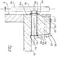
- the opening 38 is sealed by a tube 40 which lines the opening 38.
- the tube is supported with a flange 41 on the inside 42 of the transverse rib 39 with the interposition of a sealing ring 43 and provided with an external thread 44 at the other end.
- a flange ring 45 screwed onto the thread braces the pipe 40 on the outside 46 of the rib 39, also with the interposition of a seal 47, and is guided laterally into a vertical drain pipe 48, through which rainwater is prevented from the transverse wall 7 and held.
- the ribs 14, 15 and the transverse ribs 18, 19 are kept with cover plates, which in the case of the rib 15 are generally designated 49 in FIG. 3 and generally 50 in the case of the transverse rib 18 in FIG. 4.
- the cover plates 49, 50 shown correspond to the further cover plates of the remaining ribs, which are not shown in the sections shown. These cover plates are formed in the four corners 34 to 37 of the cassette plate 11 without connection, namely placed along miter cuts.
- the sheets used for slot covering, one of which is designated 49 in FIG. 3, are designed as a deformable cover for hazard protection. On the one hand, they can bend freely in the event of an explosion due to the freedom of connection to the cover plates 50 of the transverse walls, as can be seen from the broken line at 50 in FIG. 3.
- the top 56 of the cassette plate 11 is covered with a roof skin 57.
- the inner edge 59 of the perforated plate 53 serves to store the roof skin 57 in the region of the longitudinal slots 23, 24, which are covered with the plates 49, 50.
- the displacement-proof fixing of the cassette plate is ensured by the spacers 51, which keep the slots open.
- the storage of the roof skin 57 in the area of the supports differs from the storage in the area of the longitudinal slots 23, 24 in that the water below the slot 55 can penetrate into the pipe 40 as soon as rainwater occurs in the tub. So that the rainwater cannot jump over the longitudinal ribs 14, 15, emergency drains 58 are provided above the drainage pipe 40 below the maximum level of the rainwater in the tub. These are lined with pipes 59, but are only achieved when the main drainage is blocked by pipe 40.
- cover plates 49 and 50 are fixed uniformly.
- Clamping rails 60 which are attached to the upper sides 61 of the ribs, serve this purpose.
- the inside of these rails serve as a folded edge when the cover plates are bent open under the pressure of the escaping explosion gases
- the room cell with its described panes is manufactured in a precast plant. It can be installed on site after the foundations 2, 3 have been produced. After welding the rising The ceiling plate is placed on the walls, whereupon the cover plates with the perforated plates are mounted. This work can be carried out quickly, so that an efficient production and assembly of the explosion-protected Stahlbeonraumzelle 1 is guaranteed.
Landscapes
- Engineering & Computer Science (AREA)
- Architecture (AREA)
- Civil Engineering (AREA)
- Structural Engineering (AREA)
- Power Engineering (AREA)
- Environmental & Geological Engineering (AREA)
- Physics & Mathematics (AREA)
- Electromagnetism (AREA)
- Building Environments (AREA)
Applications Claiming Priority (2)
| Application Number | Priority Date | Filing Date | Title |
|---|---|---|---|
| DE19924210248 DE4210248A1 (de) | 1992-03-28 | 1992-03-28 | Explosionsgeschützte Stahlbetonraumzelle, insbesondere Stahlbetonraumzellentrafostation |
| DE4210248 | 1992-03-28 |
Publications (1)
| Publication Number | Publication Date |
|---|---|
| EP0563659A1 true EP0563659A1 (fr) | 1993-10-06 |
Family
ID=6455333
Family Applications (1)
| Application Number | Title | Priority Date | Filing Date |
|---|---|---|---|
| EP93104108A Withdrawn EP0563659A1 (fr) | 1992-03-28 | 1993-03-13 | Elément de construction préfabriqué en béton armé protégé contre les explosions spécialement élément de construction en béton armé pour transformateur |
Country Status (2)
| Country | Link |
|---|---|
| EP (1) | EP0563659A1 (fr) |
| DE (1) | DE4210248A1 (fr) |
Cited By (1)
| Publication number | Priority date | Publication date | Assignee | Title |
|---|---|---|---|---|
| GB2276894A (en) * | 1993-04-07 | 1994-10-12 | Kinpars Ind Plastics Ltd | Roofing system for building subject to internal pressure |
Citations (2)
| Publication number | Priority date | Publication date | Assignee | Title |
|---|---|---|---|---|
| DE2110093A1 (de) * | 1971-03-03 | 1972-09-21 | Müller, Gervin, 6833 Kirrlach | Fertigdach, für explosionsgefährdete Gebäude |
| EP0103221A2 (fr) * | 1982-09-14 | 1984-03-21 | Betonbau GmbH | Cellule-close transportable en béton |
-
1992
- 1992-03-28 DE DE19924210248 patent/DE4210248A1/de not_active Withdrawn
-
1993
- 1993-03-13 EP EP93104108A patent/EP0563659A1/fr not_active Withdrawn
Patent Citations (2)
| Publication number | Priority date | Publication date | Assignee | Title |
|---|---|---|---|---|
| DE2110093A1 (de) * | 1971-03-03 | 1972-09-21 | Müller, Gervin, 6833 Kirrlach | Fertigdach, für explosionsgefährdete Gebäude |
| EP0103221A2 (fr) * | 1982-09-14 | 1984-03-21 | Betonbau GmbH | Cellule-close transportable en béton |
Cited By (2)
| Publication number | Priority date | Publication date | Assignee | Title |
|---|---|---|---|---|
| GB2276894A (en) * | 1993-04-07 | 1994-10-12 | Kinpars Ind Plastics Ltd | Roofing system for building subject to internal pressure |
| GB2276894B (en) * | 1993-04-07 | 1996-10-02 | Kinpars Ind Plastics Ltd | Roofing system |
Also Published As
| Publication number | Publication date |
|---|---|
| DE4210248A1 (de) | 1993-09-30 |
Similar Documents
| Publication | Publication Date | Title |
|---|---|---|
| DE2634295C3 (de) | Kernreaktoranlage | |
| DE2634356C3 (de) | Kerntechnische Anlage | |
| DE4439754A1 (de) | Hochwasserschutzelement aus Stahl | |
| EP0054918B1 (fr) | Dispositif pour l'introduction de tuyaux ou conduits d'installation dans un bâtiment à cave | |
| EP2350538B1 (fr) | Installation photovoltaïque | |
| DE19912012C2 (de) | Notablaufvorrichtung | |
| DE3840240C2 (de) | Druckentlastungsvorrichtung an Gebäuden | |
| EP0566860A2 (fr) | Cellule-close en béton armé antidéflagrante, en particulier cellule-close-poste de transformation en béton armé | |
| DE4210248A1 (de) | Explosionsgeschützte Stahlbetonraumzelle, insbesondere Stahlbetonraumzellentrafostation | |
| DE2915431A1 (de) | Druckentlastungsvorrichtung | |
| EP3935233A1 (fr) | Dispositif de drainage | |
| EP1013844B1 (fr) | Ecoulement d'eau | |
| DE29519911U1 (de) | Dichtung für eine Fuge zwischen zwei Betonwänden | |
| WO2013189764A1 (fr) | Armoire de commande souterraine conçue pour une installation électrique | |
| EP3605763B1 (fr) | Cage souterraine, en particulier pour la distribution d'énergie et/ou la télécommunication | |
| EP1724400A1 (fr) | Coffrage des canaux | |
| WO2018024801A1 (fr) | Module photovoltaïque, procédé de réalisation d'un module photovoltaïque, montant profilé pour un cadre profilé, cadre profilé et système photovoltaïque | |
| DE102009012046A1 (de) | Auffanggrube für eine Waschstraße | |
| DE102005048304A1 (de) | Hochwasserschutzeinrichtung | |
| DE3007947A1 (de) | Dachabdeckung | |
| EP0103221B1 (fr) | Cellule-close transportable en béton | |
| DE102011106754A1 (de) | Fermenterwand eines Fermenterbehälters einer Biogasanlage | |
| DE3233989C2 (de) | Transportable Beton-Raumzelle | |
| DE202011000243U1 (de) | Vorrichtung zum wasserdichten Verschließen einer Maueröffnung in einem Gebäude | |
| DE3900880C1 (en) | Canopy for a landfill site |
Legal Events
| Date | Code | Title | Description |
|---|---|---|---|
| PUAI | Public reference made under article 153(3) epc to a published international application that has entered the european phase |
Free format text: ORIGINAL CODE: 0009012 |
|
| AK | Designated contracting states |
Kind code of ref document: A1 Designated state(s): AT BE CH DE FR GB LI LU NL |
|
| 17P | Request for examination filed |
Effective date: 19940127 |
|
| 17Q | First examination report despatched |
Effective date: 19951019 |
|
| 18D | Application deemed to be withdrawn |
Effective date: 19960430 |