EP0103221A2 - Cellule-close transportable en béton - Google Patents
Cellule-close transportable en béton Download PDFInfo
- Publication number
- EP0103221A2 EP0103221A2 EP83108376A EP83108376A EP0103221A2 EP 0103221 A2 EP0103221 A2 EP 0103221A2 EP 83108376 A EP83108376 A EP 83108376A EP 83108376 A EP83108376 A EP 83108376A EP 0103221 A2 EP0103221 A2 EP 0103221A2
- Authority
- EP
- European Patent Office
- Prior art keywords
- cover
- ventilation
- cell according
- room cell
- flat roof
- Prior art date
- Legal status (The legal status is an assumption and is not a legal conclusion. Google has not performed a legal analysis and makes no representation as to the accuracy of the status listed.)
- Granted
Links
Images

Classifications
-
- E—FIXED CONSTRUCTIONS
- E04—BUILDING
- E04B—GENERAL BUILDING CONSTRUCTIONS; WALLS, e.g. PARTITIONS; ROOFS; FLOORS; CEILINGS; INSULATION OR OTHER PROTECTION OF BUILDINGS
- E04B1/00—Constructions in general; Structures which are not restricted either to walls, e.g. partitions, or floors or ceilings or roofs
- E04B1/62—Insulation or other protection; Elements or use of specified material therefor
- E04B1/92—Protection against other undesired influences or dangers
- E04B1/98—Protection against other undesired influences or dangers against vibrations or shocks; against mechanical destruction, e.g. by air-raids
-
- F—MECHANICAL ENGINEERING; LIGHTING; HEATING; WEAPONS; BLASTING
- F24—HEATING; RANGES; VENTILATING
- F24F—AIR-CONDITIONING; AIR-HUMIDIFICATION; VENTILATION; USE OF AIR CURRENTS FOR SCREENING
- F24F7/00—Ventilation
-
- E—FIXED CONSTRUCTIONS
- E04—BUILDING
- E04B—GENERAL BUILDING CONSTRUCTIONS; WALLS, e.g. PARTITIONS; ROOFS; FLOORS; CEILINGS; INSULATION OR OTHER PROTECTION OF BUILDINGS
- E04B1/00—Constructions in general; Structures which are not restricted either to walls, e.g. partitions, or floors or ceilings or roofs
- E04B1/343—Structures characterised by movable, separable, or collapsible parts, e.g. for transport
- E04B1/34336—Structures movable as a whole, e.g. mobile home structures
-
- E—FIXED CONSTRUCTIONS
- E04—BUILDING
- E04H—BUILDINGS OR LIKE STRUCTURES FOR PARTICULAR PURPOSES; SWIMMING OR SPLASH BATHS OR POOLS; MASTS; FENCING; TENTS OR CANOPIES, IN GENERAL
- E04H5/00—Buildings or groups of buildings for industrial or agricultural purposes
- E04H5/02—Buildings or groups of buildings for industrial purposes, e.g. for power-plants or factories
- E04H5/04—Transformer houses; Substations or switchgear houses
Definitions
- the invention relates to a transportable concrete room cell according to the preamble of claim 1.
- a transportable concrete room cell with a flat roof which has ventilation slots in the area between the flat roof and the outer walls of the room cell for venting the room cell.
- the arrangement of ventilation slots in the area between the flat roof and the outer walls of the room cell has proven very successful, since the exhaust air heated during normal operation of the room cell rises in the room cell due to thermal convection, is collected under the roof and is then advantageously discharged from there to the outside. This also and particularly applies to the hot gases that are generated during an explosion inside the room cell should be derived as quickly and safely as possible.
- the exhaust air flows out of the interior to the outside through the ventilation slots directed upwards. This is important if precautions must be taken to ensure that hot exhaust gases can also escape from the room cell - for example in the event of an explosion in the interior of the room cell - which should be safely discharged for passers-by in the vicinity of the room cell.
- the ventilation slots open at the top are disadvantageous because the ventilation openings covered by a perforated plate can be quickly clogged by the dust or snow , so that the ventilation of the room cell is significantly disturbed or completely prevented.
- the present invention has for its object to improve the known concrete room cells of this type so that their manufacture can be carried out regardless of whether the exhaust air should be directed upwards or downwards into the outside environment of the room cell.
- the aim is an economical solution for the production of such room cells, in which the direction of the discharge of the exhaust air from the room cell may need to be determined at the installation site.
- the outer cover of the ventilation slots should be like this be designed so that it can be easily attached to the outside of the room cell and fits well into the architectural picture of the room cell.
- the two profile sheets can be easily attached to the outside of the room cell. It is only necessary to decide at the time of attachment whether the exhaust air should be discharged upwards or downwards.
- the first profiled sheet consists of non-perforated material and, together with the ledge of the flat roof, forms the overall ledge of the room cell. Manufacturing tolerances in the ventilation slots arranged in the area between the flat roof and the outer walls of the room cell can be easily compensated for by the channel-shaped covers, so that a clean design of this area of the room cell results.
- interesting relief-like structures of the ledge of the room cell can be achieved through different designs of the cover.
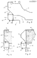
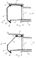
- a flat roof 11 rests on an outer wall 10 of a concrete room cell.
- Ventilation slots 12 are cut out between the two along the entire circumference of the room cell, in the exemplary embodiments according to FIG. 1 to 4 from the flat roof 11 and according to the embodiment. 5 from the outer wall 10.
- a channel-shaped cover 13 is provided which runs around the entire circumference of the room cell.
- This cover 13 consists of two clipped profile sheets, namely a first profile sheet 14 made of an unperforated sheet or plastic material and a second profile sheet 16, 17 made of a perforated material.
- the vertical section of the profiled sheet 14 is aligned with the end face of the roof ledge 15 of the flat roof 11 and forms the overall ledge of the room cell with the roof ledge.
- the second profiled sheet 16, 17 closes the ventilation slots 12 on the outside thereof in a puncture-proof manner, the perforated wall 16 in each case the vertical wall arranged directly in front of the outwardly facing end piece of the ventilation slots 12 and the perforated wall 17 the horizontal, optionally upward or downward wall of the second profile sheet.
- the two perforated walls 16 and 17 are thus connected in series in the direction of flow, so that there is a particularly high level of security against the ingress of dust, flying snow or small animals into the interior of the room cell.
- the holes in the perforated walls 16 and 17 have a diameter of 2.5 mm and a pitch of 3.5 mm.
- the total free ventilation cross-section is calculated so that it is sufficient to vent the room cell.
- at least the perforated wall 16 consists of a fire protection plate made of a urea-formaldehyde resin, which foams when hot exhaust gases of an explosion pressure wave from the interior of the room cell and thus contributes to cooling the gases flowing outwards.
- the same pressing tool can always be used to produce the covers 13 of the various exemplary embodiments. This leads to a particularly inexpensive solution.
- Fig. 2 is a sufficiently wide flow path for the exhaust air upwards, was only inserted a triangular rail in the concreting mold in the manufacture of the concrete flat roof 11, so that the outer lower edge of the flat roof is chamfered. This is also in the embodiment.
- Fig. 3 the case.
- the profiled sheet 14 of the cover 13 provided there has a widening 23 which extends upwards and which covers the roof ledge 15 over its entire height and encompasses its upper edge over the entire width of an edge strip 24 which is raised in relation to the upper side.
- a plastic film not shown in the drawing.
- This plastic film is in turn protected by a gravel covering against UV radiation up to the edge strip 24, on which a gravel covering would not stick. Therefore, the embodiment according to Fig. 3 - as well as the following leadership examples acc. 4 and 5 - a very useful embodiment, because here the unprotected edge strip 24 of the flat roof 11 is covered by the widening 23 of the profiled sheet 14.
- Fig. 5 Also in the embodiment according to Fig. 5 is the roof ledge 15 of the flat roof 11, which is flush here with the outer wall 10, covered by sheet metal profiles. Another solid sheet profile 20 is attached to the profile sheet 16 , 17, which together with the profile sheet 14 forms the overall ledge of the room cell.
- the joints between the flat roof 11 or the outer wall 10 on the one hand and the cover 13 on the other hand can be filled with a sealing compound 19 if necessary. In the embodiments according to 2 to 5 this is indicated in some places. Furthermore, a snow deflector 21 can be provided on the downward-facing perforated wall 17 of the second profiled sheet (FIG. 1) and finally a drip nose 18 and / or a rain gutter 22 can be formed on the profiled sheet 14 of the cover 13.
- the embodiments acc. 3 to 5 are more expensive than those according to. 1 and 2, but stand out In addition to the protective overlap of the edge strip 24 already mentioned, it can be attached to the room cell in a particularly problem-free manner, since no consideration must be given to the manufacturing tolerances of the flat roof 11 and / or the ventilation slots 12.
Landscapes
- Engineering & Computer Science (AREA)
- Architecture (AREA)
- Structural Engineering (AREA)
- Civil Engineering (AREA)
- Mechanical Engineering (AREA)
- General Engineering & Computer Science (AREA)
- Chemical & Material Sciences (AREA)
- Combustion & Propulsion (AREA)
- Physics & Mathematics (AREA)
- Electromagnetism (AREA)
- Power Engineering (AREA)
- Environmental & Geological Engineering (AREA)
- Building Environments (AREA)
- Buildings Adapted To Withstand Abnormal External Influences (AREA)
Priority Applications (1)
| Application Number | Priority Date | Filing Date | Title |
|---|---|---|---|
| AT83108376T ATE20105T1 (de) | 1982-09-14 | 1983-08-25 | Transportable beton-raumzelle. |
Applications Claiming Priority (2)
| Application Number | Priority Date | Filing Date | Title |
|---|---|---|---|
| DE3233988 | 1982-09-14 | ||
| DE19823233988 DE3233988A1 (de) | 1982-09-14 | 1982-09-14 | Transportable beton-raumzelle |
Publications (3)
| Publication Number | Publication Date |
|---|---|
| EP0103221A2 true EP0103221A2 (fr) | 1984-03-21 |
| EP0103221A3 EP0103221A3 (en) | 1985-01-30 |
| EP0103221B1 EP0103221B1 (fr) | 1986-05-28 |
Family
ID=6173143
Family Applications (1)
| Application Number | Title | Priority Date | Filing Date |
|---|---|---|---|
| EP83108376A Expired EP0103221B1 (fr) | 1982-09-14 | 1983-08-25 | Cellule-close transportable en béton |
Country Status (3)
| Country | Link |
|---|---|
| EP (1) | EP0103221B1 (fr) |
| AT (1) | ATE20105T1 (fr) |
| DE (2) | DE3233988A1 (fr) |
Cited By (3)
| Publication number | Priority date | Publication date | Assignee | Title |
|---|---|---|---|---|
| EP0363949A1 (fr) * | 1988-10-13 | 1990-04-18 | Betonbau GmbH | Toit transportable |
| FR2644191A1 (fr) * | 1989-03-10 | 1990-09-14 | Betonbau Gmbh | Construction transportable avec toit transportable separement |
| EP0563659A1 (fr) * | 1992-03-28 | 1993-10-06 | SEPRO & CO. | Elément de construction préfabriqué en béton armé protégé contre les explosions spécialement élément de construction en béton armé pour transformateur |
Families Citing this family (1)
| Publication number | Priority date | Publication date | Assignee | Title |
|---|---|---|---|---|
| DE19706320C2 (de) * | 1996-02-19 | 2002-05-08 | Betonbau Gmbh | Transportables Dach |
Family Cites Families (2)
| Publication number | Priority date | Publication date | Assignee | Title |
|---|---|---|---|---|
| DE2110089C3 (de) * | 1971-03-03 | 1974-04-04 | Gervin 6833 Kirrlach Mueller | Explosionsgefährdetes, im wesentlichen einzelliges Gebäude |
| DE2706958A1 (de) * | 1977-02-18 | 1978-08-31 | Gervin Josef Mueller | Explosionsgefaehrdetes gebaeude mit mindestens einer entlueftungsoeffnung |
-
1982
- 1982-09-14 DE DE19823233988 patent/DE3233988A1/de not_active Withdrawn
-
1983
- 1983-08-25 AT AT83108376T patent/ATE20105T1/de not_active IP Right Cessation
- 1983-08-25 DE DE8383108376T patent/DE3363768D1/de not_active Expired
- 1983-08-25 EP EP83108376A patent/EP0103221B1/fr not_active Expired
Cited By (3)
| Publication number | Priority date | Publication date | Assignee | Title |
|---|---|---|---|---|
| EP0363949A1 (fr) * | 1988-10-13 | 1990-04-18 | Betonbau GmbH | Toit transportable |
| FR2644191A1 (fr) * | 1989-03-10 | 1990-09-14 | Betonbau Gmbh | Construction transportable avec toit transportable separement |
| EP0563659A1 (fr) * | 1992-03-28 | 1993-10-06 | SEPRO & CO. | Elément de construction préfabriqué en béton armé protégé contre les explosions spécialement élément de construction en béton armé pour transformateur |
Also Published As
| Publication number | Publication date |
|---|---|
| ATE20105T1 (de) | 1986-06-15 |
| DE3233988A1 (de) | 1984-03-15 |
| EP0103221B1 (fr) | 1986-05-28 |
| EP0103221A3 (en) | 1985-01-30 |
| DE3363768D1 (en) | 1986-07-03 |
Similar Documents
| Publication | Publication Date | Title |
|---|---|---|
| DE2935745C2 (de) | Lärmschutzwand | |
| DE2156189C2 (de) | Dachentlüfter | |
| CH653089A5 (en) | Metal blind | |
| DE3320850C2 (fr) | ||
| EP0045489B1 (fr) | Elément de ventilation | |
| EP0103221B1 (fr) | Cellule-close transportable en béton | |
| DE2842412C2 (fr) | ||
| DE2915431C2 (fr) | ||
| DE2110093C3 (de) | Fertigdach für explosionsgefährdete Gebäude | |
| DE19860160C2 (de) | Wasserablauf | |
| DE3233989C2 (de) | Transportable Beton-Raumzelle | |
| DE2528300C3 (de) | Schaltschrank mit dicht schließender Tür | |
| DE4210901A1 (de) | Explosionsgeschützte Stahlbetonraumzelle, insbesondere Stahlbetonraumzellentrafostation | |
| AT391200B (de) | Belueftungseinrichtung | |
| EP3258049A1 (fr) | Dispositif destiné à recouvrir la zone extérieure de la limite inférieure d'une ouverture de bâtiment | |
| CH653118A5 (en) | Ventilation device for installation in windows or other wall openings of buildings | |
| DE3313875A1 (de) | Hohles first- oder gratabdeckelement mit lueftungsoeffnungen | |
| DE8225826U1 (de) | Transportable beton-raumzelle | |
| EP0450265B1 (fr) | Revêtement de bord pour rebords de fenêtre minces | |
| DE3106278C2 (de) | Lüftungsvorrichtung für Dächer | |
| DE9000648U1 (de) | Wetterschutzgitter für Schornsteine | |
| DE3313008C2 (fr) | ||
| DE2625575A1 (de) | Entlueftungsvorrichtung fuer gebaeude | |
| DE8225827U1 (de) | Transportable beton-raumzelle | |
| DE2451058A1 (de) | Firstenlueftung an daechern |
Legal Events
| Date | Code | Title | Description |
|---|---|---|---|
| PUAI | Public reference made under article 153(3) epc to a published international application that has entered the european phase |
Free format text: ORIGINAL CODE: 0009012 |
|
| AK | Designated contracting states |
Designated state(s): AT CH DE FR LI |
|
| PUAL | Search report despatched |
Free format text: ORIGINAL CODE: 0009013 |
|
| AK | Designated contracting states |
Designated state(s): AT CH DE FR LI |
|
| 17P | Request for examination filed |
Effective date: 19841215 |
|
| GRAA | (expected) grant |
Free format text: ORIGINAL CODE: 0009210 |
|
| AK | Designated contracting states |
Kind code of ref document: B1 Designated state(s): AT CH DE FR LI |
|
| REF | Corresponds to: |
Ref document number: 20105 Country of ref document: AT Date of ref document: 19860615 Kind code of ref document: T |
|
| REF | Corresponds to: |
Ref document number: 3363768 Country of ref document: DE Date of ref document: 19860703 |
|
| ET | Fr: translation filed | ||
| PLBE | No opposition filed within time limit |
Free format text: ORIGINAL CODE: 0009261 |
|
| STAA | Information on the status of an ep patent application or granted ep patent |
Free format text: STATUS: NO OPPOSITION FILED WITHIN TIME LIMIT |
|
| 26N | No opposition filed | ||
| PGFP | Annual fee paid to national office [announced via postgrant information from national office to epo] |
Ref country code: FR Payment date: 19960718 Year of fee payment: 14 |
|
| PGFP | Annual fee paid to national office [announced via postgrant information from national office to epo] |
Ref country code: AT Payment date: 19960831 Year of fee payment: 14 |
|
| PGFP | Annual fee paid to national office [announced via postgrant information from national office to epo] |
Ref country code: CH Payment date: 19961202 Year of fee payment: 14 |
|
| PG25 | Lapsed in a contracting state [announced via postgrant information from national office to epo] |
Ref country code: AT Free format text: LAPSE BECAUSE OF NON-PAYMENT OF DUE FEES Effective date: 19970825 |
|
| PG25 | Lapsed in a contracting state [announced via postgrant information from national office to epo] |
Ref country code: LI Free format text: LAPSE BECAUSE OF NON-PAYMENT OF DUE FEES Effective date: 19970831 Ref country code: CH Free format text: LAPSE BECAUSE OF NON-PAYMENT OF DUE FEES Effective date: 19970831 |
|
| REG | Reference to a national code |
Ref country code: CH Ref legal event code: PL |
|
| PG25 | Lapsed in a contracting state [announced via postgrant information from national office to epo] |
Ref country code: FR Free format text: LAPSE BECAUSE OF NON-PAYMENT OF DUE FEES Effective date: 19980430 |
|
| REG | Reference to a national code |
Ref country code: FR Ref legal event code: ST |
|
| PGFP | Annual fee paid to national office [announced via postgrant information from national office to epo] |
Ref country code: DE Payment date: 20020918 Year of fee payment: 20 |