EP0563684A2 - Method for supervising and observing a technical process - Google Patents
Method for supervising and observing a technical process Download PDFInfo
- Publication number
- EP0563684A2 EP0563684A2 EP93104363A EP93104363A EP0563684A2 EP 0563684 A2 EP0563684 A2 EP 0563684A2 EP 93104363 A EP93104363 A EP 93104363A EP 93104363 A EP93104363 A EP 93104363A EP 0563684 A2 EP0563684 A2 EP 0563684A2
- Authority
- EP
- European Patent Office
- Prior art keywords
- error
- automation system
- location
- monitoring
- configuration data
- Prior art date
- Legal status (The legal status is an assumption and is not a legal conclusion. Google has not performed a legal analysis and makes no representation as to the accuracy of the status listed.)
- Granted
Links
Images




Classifications
-
- G—PHYSICS
- G05—CONTROLLING; REGULATING
- G05B—CONTROL OR REGULATING SYSTEMS IN GENERAL; FUNCTIONAL ELEMENTS OF SUCH SYSTEMS; MONITORING OR TESTING ARRANGEMENTS FOR SUCH SYSTEMS OR ELEMENTS
- G05B23/00—Testing or monitoring of control systems or parts thereof
- G05B23/02—Electric testing or monitoring
- G05B23/0205—Electric testing or monitoring by means of a monitoring system capable of detecting and responding to faults
- G05B23/0259—Electric testing or monitoring by means of a monitoring system capable of detecting and responding to faults characterized by the response to fault detection
- G05B23/0267—Fault communication, e.g. human machine interface [HMI]
Definitions
- the present invention relates to a monitoring method for a technical process and the automation system which monitors and controls the technical process, in which the automation system transmits messages to a monitoring system superordinate to the automation system, from which the messages are evaluated and from which the evaluation results by means of a, preferably graphics-capable, Display devices can be represented, and an observation system for performing the method.
- a graphical diagram of the system or the process is generally shown on a screen.
- the observation system also takes care of displaying and documenting messages.
- an error in automation e.g. a wire break of a peripheral connection
- such an error is usually displayed graphically in its effects, e.g. by highlighting or flashing the part of the system in which the error occurred.
- a message text is usually displayed on the screen. This message text is also printed out on a printer as an error list.
- the object of the present invention is to support the user of the automation system in troubleshooting and error localization.
- the user should know exactly at or in which module and at which location the error has occurred.
- the monitoring method has several process representations, it is advantageous if the hierarchical representation of a fault location can be started from any process representation. In this case, it is not necessary to go back to the overall representation of the process or the system if an error has occurred somewhere in the process or in the system.
- a fault location is displayed in a graphical representation, the fault location can be detected particularly easily and quickly by the user.
- the user receives information about the location of the fault as well as information about the type of fault that occurred.
- the automation system consists of an operator control and monitoring system 1, to which the other components of the automation system are connected via bus 2.
- the components are typically arranged in control cabinets 3.
- control cabinets 3 In the control cabinets 3 there are several subracks 4 with assemblies 5 as well as several rows 6 of electrical components 7.
- FIG. 1 only one of the control cabinets 3 has been shown in detail. The other of the control cabinets 3 have been shown only schematically for the sake of clarity.
- a large number of lines 8 run from the switch cabinets 3 to the controlled process.
- the operator control and monitoring system 1 has a processor 9 which evaluates the messages transmitted by the rest of the automation system.
- a graphics-capable monitor 10, a terminal 11 and a mouse 12 are connected to the processor 9 via the terminal 11.
- a configuration data memory 13 is also connected to the processor 9, in which the entire configuration data of the automation system are stored.
- the configuration data include, among other things, the entire circuit diagrams of the system and the layout plans of all assembly systems such as the subrack 4 and the cabinets 3 with all identification data and parameters.
- a diagram of the system, a diagram of a part of the system, a diagram of the process or a diagram of a part of the process is shown on the monitor 10.
- the displayed image of the system or of the process is continuously updated on the basis of operations or messages that the automation system transmits to the operating and monitoring system 1.
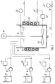
- FIG. 3 shows such a representation of the plant to be guided on the monitor 10.
- a reactor 14 is fed from the storage containers 15 to 17 via the pumps 15 'to 17'.
- the pumps 15 'to 17' are regulated by flow controllers 15 '' to 17 ''.
- the reactor mixture 18 is mixed by the stirrer 20 driven by the motor 19.
- the reactor mixture 18 flows out via the line 21 through the valve 14 '.
- the valve 14 ' is controlled by the discharge control 14' '.
- the diagram according to FIG. 3 also shows the temperature controller 22 ′′, which regulates the supply of hot water to the heating coils 22 via the valve 22 ′ in such a way that a predetermined temperature range is maintained in the reactor mixture 18.
- a level controller 23 is shown in the illustration according to FIG. 3, which, as a higher-level controller, specifies the desired values for the flow controllers 15 ′′ to 17 ′′ and the flow controller 14 ′′.
- a display according to FIG. 3, which can be a complete display of the entire system or just a partial section, on the monitor 10 of the control system 1 is quite common in automated processes.
- a representation as shown in FIG. 4 is also common. Here, for example, is the time course of setpoint w and Actual value x of one of the control loops of the reactor 14 is shown. 4, the control loop parameters are also shown on the screen in the control room 1.
- the location of the error can e.g. be implicitly given that the address of the automation device and the address of the module 5 'in which the error has occurred, or the identification of the electrical component 7', for. B. a circuit breaker in which the error has occurred is transmitted.
- the address or identification is initially only logical, i.e. not physically related to the actual location, e.g. the slot related.
- the actual fault location can only be determined by comparing the address or marking with the configuration data.
- the time at which the error occurred can either be determined by the operator control and monitoring system 1, or the time is also transmitted.
- the user of the system does not want to ignore the error message, but rather wants to localize the error more precisely, he enters a corresponding command on the terminal 11 in order to take a closer look at the geographical and the switching location of the error.
- the entry can e.g. the entry of the command "Control-S". If a mouse 12 is available to the user, it is particularly easy to call up the error analysis. In this case, the user only has to click on the field 24, which displays a special message, with the mouse 12. When the user calls the error display function, he next receives a display of the control cabinet 3 in which the error has occurred. This representation is shown in FIG. 5.
- the configuration data of the automation system are called up from the configuration data memory 13 by the processor 9.
- the processor 9 determines the control cabinet 3 in which the error occurred and its geometric structure. This structure is shown in FIG. 5 when the error representation program is called up on monitor 10.
- the number, and possibly also the location of the control cabinet 3, is displayed in the display field 25.
- FIG. 6 the number of the control cabinet 3 and that of the subrack 4 which is shown is now shown on the monitor 10 in the display field 25.
- the illustration of the subrack 4 is as in FIG. 5.
- the subassemblies 5 are again shown here, the defective assembly 5 'being optically highlighted.
- the geographical location of the error namely the assembly 5 '
- the illustration according to FIG. 6 is conclusive.
- the user can also be informed of the switching location of the fault in addition to the geographical location.
- FIG. 7 shows the part of the circuit diagram in which the fault occured.
- the circuit diagram was also determined by the processor 9 using the configuration data from the configuration data memory 13.
- the display panel 25 shows the numbers of control cabinet 3, subrack 4, assembly 5 'and the side of the circuit diagram.
- the circuit diagram of this page is also shown on the monitor 10.
- the location of the fault, this time in terms of switching technology, is optically highlighted, e.g. by flashing the border 26.
- a message about the type of error can be made on the monitor 10.
- the error detection in the automation system must be carried out so precisely that every error can be precisely localized. It is therefore not sufficient to simply recognize an error, but at least the error code and the address or the identification of the component in which the error occurred must be transmitted.
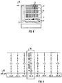
- FIG 8 which also shows the representation of the overall control cabinet 3, an error in the electrical component 7 'has been detected. If the electrical component 7 'itself cannot transmit a message to the operator control and monitoring system 1, this must take place indirectly via an automation device which then reports this error to the operator control and monitoring system 1.
- a signal which is triggered by the electrical component 7 'in the event of an error is used as the input signal of an automation device, the automation device being programmed such that it reports this error to the operator control and monitoring system 1 when the error signal is present.
- This error is also displayed on the monitor 10 after the configuration data has been called up by the processor 9.
- the display follows as before for the defective assembly 5 'by visual highlighting. The geographical location of the error is therefore sufficiently localized.
- the part of the circuit diagram of this electrical component 7' in which the error has occurred is again displayed on the monitor 10.
- the error is again, e.g. by means of the flashing border 26, optically highlighted.
- configuration data also contains the programs for the individual parts of the automation system, it is of course also possible to detect and display program errors (e.g. limit violation of a software controller or timeout of an execution level).
- the fault localization and the fault diagnosis from the control room 1 is made considerably easier by means of the monitoring method described above.
- a data memory e.g. a hard disk
- the advantage of the invention lies in the rapid localization of the fault location from the control room. In addition, it is no longer necessary to search laboriously in paper manuals.
- the monitoring process can of course not only take place in the control room, but in principle from any computer that has a graphics-capable monitor and access to the configuration data. It is e.g. It is possible to connect the control cabinets 3 to one another via a local area network (LAN) and to provide options for connecting a graphics-capable programming device to the local area network. Then when the configuration data, e.g. the method can of course also be carried out by means of the programming device by means of a floppy disk which is available to the programming device.
- LAN local area network
Landscapes
- Engineering & Computer Science (AREA)
- Human Computer Interaction (AREA)
- Physics & Mathematics (AREA)
- General Physics & Mathematics (AREA)
- Automation & Control Theory (AREA)
- Testing And Monitoring For Control Systems (AREA)
- Analysing Materials By The Use Of Radiation (AREA)
- Debugging And Monitoring (AREA)
Abstract
Description
Die vorliegende Erfindung betrifft ein Überwachungsverfahren für einen technischen Prozeß und das den technischen Prozeß überwachende und steuernde Automatisierungssystem, bei dem das Automatisierungssystem Meldungen an ein dem Automatisierungssystem übergeordnetes Beobachtungssystem übermittelt, von dem die Meldungen ausgewertet werden und von dem die Auswertungsergebnisse mittels eines, vorzugsweise graphikfähigen, Anzeigegeräts darstellbar sind, sowie ein Beobachtungssystem zur Durchführung des Verfahrens.The present invention relates to a monitoring method for a technical process and the automation system which monitors and controls the technical process, in which the automation system transmits messages to a monitoring system superordinate to the automation system, from which the messages are evaluated and from which the evaluation results by means of a, preferably graphics-capable, Display devices can be represented, and an observation system for performing the method.
Bei derartigen Überwachungsverfahren wird im Regelfall ein graphisches Schaubild der Anlage bzw. des Prozesses auf einem Bildschirm dargestellt. Das Beobachtungssystem übernimmt dabei insbesondere auch das Anzeigen und Dokumentieren von Meldungen. Beim Erkennen eines Fehlers in der Automatisierung, z.B. einem Drahtbruch eines Peripherieanschlusses, wird ein solcher Fehler üblicherweise graphisch in seinen Auswirkungen angezeigt, z.B. durch farbiges Markieren oder Blinken des Anlagenteils, in dem der Fehler aufgetreten ist. Außerdem wird im Regelfall ein Meldetext auf dem Bildschirm ausgegeben. Dieser Meldetext wird auch auf einem Drucker als Fehlerliste ausgedruckt.With such monitoring methods, a graphical diagram of the system or the process is generally shown on a screen. The observation system also takes care of displaying and documenting messages. Upon detection of an error in automation, e.g. a wire break of a peripheral connection, such an error is usually displayed graphically in its effects, e.g. by highlighting or flashing the part of the system in which the error occurred. In addition, a message text is usually displayed on the screen. This message text is also printed out on a printer as an error list.
Es ist ferner bekannt, beim Auftreten eines Fehlers die Seite im Stromlaufplan, in dem der elektrische Fehler aufgetreten ist, auf den Bildschirm graphisch darzustellen. Eine weitergehende Hilfe bei der Fehlersuche und der Fehlereingrenzung existiert jedoch nicht. Insbesondere ist aus dem Stromlaufplan oftmals nicht ersichtlich, an welchem geographischen Ort des Automatisierungssystems der Fehler aufgetreten ist. Es erfolgt auch keine graphische Unterstützung bezüglich der Lokalisierung des Fehlers innerhalb des Stromlaufplans.It is also known to graphically display the page in the circuit diagram in which the electrical error has occurred when an error occurs. However, there is no further help in troubleshooting and fault localization. In particular, the circuit diagram often does not show which one geographical location of the automation system the error occurred. There is also no graphic support regarding the location of the fault within the circuit diagram.
Die Aufgabe der vorliegenden Erfindung besteht darin, den Benutzer des Automatisierungssystems bei der Fehlersuche und Fehlerlokalisierung zu unterstützen. Insbesondere soll der Benutzer am Ende der Fehlerauswertung exakt wissen, an oder in welcher Baugruppe und an welchem Ort der Fehler aufgetreten ist.The object of the present invention is to support the user of the automation system in troubleshooting and error localization. In particular, at the end of the error evaluation, the user should know exactly at or in which module and at which location the error has occurred.
Die Aufgabe wird durch ein Überwachungsverfahren gelöst,
- bei dem vom Beobachtungssystem aus die wesentlichen Projektierungsdaten, vorzugsweise die gesamten Projektierungsdaten, des Automatisierungssystems zugänglich sind,
- und bei dem beim Erkennen eines Fehlers im Automatisierungssystem, z.B. einer defekten Baugruppe oder eines Drahtbruchs in der Peripheriebeschaltung, der Ort des Fehlers hierarchieartig abgestuft darstellbar ist.
- in which the essential configuration data, preferably the entire configuration data, of the automation system are accessible from the observation system,
- and in the case of detection of a fault in the automation system, for example a defective module or a wire break in the peripheral circuitry, the location of the fault can be represented in a hierarchical manner.
Wenn das Überwachungsverfahren mehrere Prozeßdarstellungen aufweist, ist es von Vorteil, wenn das hierarchieartig abgestufte Darstellen eines Fehlerortes von jeder Prozeßdarstellung aus startbar ist. In diesem Fall muß nämlich nicht auf die Gesamtdarstellung des Prozesses bzw. der Anlage zurückgegangen werden, wenn irgendwo im Prozeß bzw. in der Anlage ein Fehler aufgetreten ist.If the monitoring method has several process representations, it is advantageous if the hierarchical representation of a fault location can be started from any process representation. In this case, it is not necessary to go back to the overall representation of the process or the system if an error has occurred somewhere in the process or in the system.
Wenn das Darstellen eines Fehlerortes in graphischer Darstellung erfolgt, ist der Fehlerort durch den Benutzer besonders leicht und schnell erfaßbar.If a fault location is displayed in a graphical representation, the fault location can be detected particularly easily and quickly by the user.
Wenn die Darstellungsstufen sowohl Darstellungen über den geographischen Ort als auch Darstellungen über den schalttechnischen Ort des Fehlers beinhalten, erhält der Benutzer sowohl Informationen über den Ort, an dem der Fehler aufgetreten ist, als auch Informationen über die Art des aufgetretenen Fehlers.If the display levels include both the geographical location and the circuitry location of the fault, the user receives information about the location of the fault as well as information about the type of fault that occurred.
Wenn das Automatisierungssystem in Schaltschränken angeordnet ist, wobei jeder Schaltschrank mindestens einen Baugruppenträger mit Baugruppen aufweist, ist es von Vorteil, wenn
- bei der Darstellung des Fehlerortes zunächst der Aufbau des Schaltschrankes dargestellt wird, wobei die Baugruppe, in der der Fehler aufgetreten ist, hervorgehoben ist,
- sodann der Baugruppenträger mit Baugruppen dargestellt wird, in der sich die Baugruppe befindet, in der der Fehler aufgetreten ist, wobei die Baugruppe hervorgehoben ist, und
- gegebenenfalls der Stromlaufplan der Baugruppe, in deren Peripheriebeschaltung der Fehler aufgetreten ist, dargestellt wird, wobei der Stromkreis, in dem der Fehler aufgetreten ist, hervorgehoben ist.
- when the location of the error is displayed, the structure of the control cabinet is shown, with the module in which the error occurred highlighted,
- then the subrack is displayed with assemblies in which the assembly in which the error has occurred, with the assembly being highlighted, and
- if applicable, the circuit diagram of the module in whose peripheral circuitry the error has occurred is shown, with the circuit in which the error has been highlighted.
Weitere Vorteile und Einzelheiten ergeben sich aus der nachfolgenden Beschreibung eines Ausführungsbeispiels, anhand der Zeichnungen und in Verbindung mit den weiteren Unteransprüchen. Es zeigen:
- FIG 1
- eine Prinzipdarstellung eines Automatisierungssystems,
- FIG 2
- eine Prinzipdarstellung des Bedien- und Beobachtungssystems,
- FIG 3
- eine beispielhafte Darstellung einer Anlage,
- FIG 4
- eine beispielhafte Darstellung eines Regelkreises,
- FIG 5
- eine Darstellung eines Schaltschranks,
- FIG 6
- eine Darstellung eines Baugruppenträgers mit Baugruppen,
- FIG 7
- einen Teil des Stromlaufplans der Peripheriebeschaltung einer Baugruppe,
- FIG 8
- einen Schaltschrank und
- FIG 9
- einen Teil des Stromlaufplans der Peripheriebeschaltung einer elektrischen Komponente.
- FIG. 1
- a schematic diagram of an automation system,
- FIG 2
- a schematic diagram of the operating and monitoring system,
- FIG 3
- an exemplary representation of a system,
- FIG 4
- an exemplary representation of a control loop,
- FIG 5
- a representation of a control cabinet,
- FIG 6
- a representation of a rack with assemblies,
- FIG 7
- a part of the circuit diagram of the peripheral circuitry of a module,
- FIG 8
- a control cabinet and
- FIG. 9
- a part of the circuit diagram of the peripheral circuitry of an electrical component.
Gemäß FIG 1 besteht das Automatisierungssystem aus einem Bedien- und Beobachtungssystem 1, an das über den Bus 2 die anderen Komponenten des Automatisierungssystems angeschlossen sind. Die Komponenten sind typisch in Schaltschränken 3 angeordnet. In den Schaltschränken 3 befinden sich mehrere Baugruppenträger 4 mit Baugruppen 5 sowie mehrere Reihen 6 von elektrischen Komponenten 7. In FIG 1 wurde nur einer der Schaltschränke 3 detailliert dargestellt. Die anderen der Schaltschränke 3 wurden der besseren Übersichtlichkeit halber nur schematisch dargestellt. Von den Schaltschränken 3 aus verläuft eine Vielzahl von Leitungen 8 zum gesteuerten Prozeß.According to FIG. 1, the automation system consists of an operator control and
Gemäß FIG 2 weist das Bedien- und Beobachtungssystem 1 einen Prozessor 9 auf, der die vom Rest des Automatisierungssystems übertragenen Meldungen auswertet. An den Prozessor 9 sind ein graphikfähiger Monitor 10, ein Terminal 11 sowie über das Terminal 11 eine Maus 12 angeschlossen. Weiterhin ist an den Prozessor 9 ein Projektierungsdatenspeicher 13 angeschlossen, in dem die gesamten Projektierungsdaten des Automatisierungssystems abgespeichert sind. Die Projektierungsdaten umfassen u.a. die gesamten Stromlaufpläne der Anlage und die Anordnungspläne aller Aufbausysteme wie z.B. der Baugruppenträger 4 und der Schränke 3 mit allen Kennzeichungsdaten und Parametern.According to FIG. 2, the operator control and
Im Normalbetrieb des Automatisierungssystems wird auf dem Monitor 10 ein Schaubild der Anlage, ein Schaubild eines Teils der Anlage, ein Schaubild des Prozesses bzw. ein Schaubild eines Teils des Prozesses dargestellt. Das dargestellte Bild der Anlage bzw. des Prozesses wird dabei laufend aufgrund von Bedienungen oder Meldungen, die das Automatisierungssystem an das Bedien- und Beobachtungssystem 1 übermittelt, aktualisiert.In normal operation of the automation system, a diagram of the system, a diagram of a part of the system, a diagram of the process or a diagram of a part of the process is shown on the
FIG 3 zeigt eine solche Darstellung der zu führenden Anlage auf dem Monitor 10. Gemäß FIG 3 wird ein Reaktor 14 aus den Vorratsbehältern 15 bis 17 über die Pumpen 15' bis 17' beschickt. Die Pumpen 15' bis 17' werden durch Durchflußregler 15'' bis 17'' geregelt. Im Reaktor 14 wird das Reaktorgemisch 18 durch den vom Motor 19 angetriebenen Rührer 20 vermischt. Das Reaktorgemisch 18 fließt über die Leitung 21 durch das Ventil 14' ab. Das Ventil 14' wird dabei von der Abflußsteuerung 14'' gesteuert. Weiterhin ist im Schaubild gemäß FIG 3 noch der Temperaturregler 22'' dargestellt, der über das Ventil 22' die Zufuhr von Heißwasser zu den Heizschlangen 22 derart regelt, daß im Reaktorgemisch 18 ein vorbestimmter Temperaturbereich eingehalten wird. Ferner ist in der Darstellung gemäß FIG 3 noch ein Niveauregler 23 dargestellt, der als übergeordneter Regler den Durchflußreglern 15'' bis 17'' und der Abflußsteuerung 14'' ihre Sollwerte vorgibt.3 shows such a representation of the plant to be guided on the
Eine Darstellung gemäß FIG 3, die eine Volldarstellung der gesamten Anlage oder aber auch nur ein Teiiausschnitt sein kann, auf dem Monitor 10 des Leitsystems 1 ist bei automatisierten Prozessen durchaus üblich. Auch eine Darstellung wie sie in FIG 4 gezeigt ist, ist allgemein üblich. Hier ist z.B. der zeitliche Verlauf von Sollwert w und Istwert x eines der Regelkreise des Reaktors 14 dargestellt. Weiterhin werden gemäß FIG 4 auf dem Bildschirm in der Leitwarte 1 auch nach die Regelkreisparameter dargestellt.A display according to FIG. 3, which can be a complete display of the entire system or just a partial section, on the
Wenn nun in der überwachten Anlage bzw. im überwachten Prozeß ein Leittechnikfehler auftritt, so erfolgt eine entsprechende Meldung an das Bedien- und Beobachtungssystem 1. Als Leittechnikfehler wird dabei jeder Fehler im Automatisierungssystem angesehen, z.B. ein Drahtbruch in einer der Leitungen 8. Die an das Bedien- und Beobachtungssystem 1 übertragene Meldung umfaßt zumindest folgende Informationen:
- Einen Code für die Art des aufgetretenen Fehlers,
- einen Code für den Ort des Fehlers sowie
- die Zeit des Fehlers.
- A code for the type of error that occurred,
- a code for the location of the error as well
- the time of failure.
Der Ort des Fehlers kann z.B. implizit dadurch gegeben sein, daß die Adresse des Automatisierungsgeräts sowie die Adresse der Baugruppe 5', in der der Fehler aufgetreten ist, bzw. die Kennzeichnung der elektrischen Komponente 7', z. B. eines Sicherungsautomaten, in der der Fehler aufgetreten ist, übertragen wird. Die Adresse bzw. die Kennzeichnung ist zunächst nur logisch, also nicht physikalisch auf den tatsächlichen Ort, z.B. den Steckplatz, bezogen. Erst durch den Vergleich von Adresse bzw. Kennzeichnung mit den Projektierungsdaten ist der tatsächliche Fehlerort bestimmbar. Die Zeit, zu der der Fehler aufgetreten ist, kann entweder vom Bedien- und Beobachtungssystem 1 bestimmt werden oder aber die Zeit wird ebenfalls mit übertragen.The location of the error can e.g. be implicitly given that the address of the automation device and the address of the module 5 'in which the error has occurred, or the identification of the electrical component 7', for. B. a circuit breaker in which the error has occurred is transmitted. The address or identification is initially only logical, i.e. not physically related to the actual location, e.g. the slot related. The actual fault location can only be determined by comparing the address or marking with the configuration data. The time at which the error occurred can either be determined by the operator control and
Der Fehler wird unmittelbar nach seiner Meldung sofort in das momentan dargestellte Bild eingeblendet, unabhängig davon, ob das momentan dargestellte Bild den Gesamtprozeß, die Gesamtanlage oder Teile davon darstellt. Schematisch ist dies in FIG 4 für einen detektierten Drahtbruch gezeigt.Immediately after it has been reported, the error is superimposed on the image currently displayed, regardless of whether the image currently displayed represents the overall process, the overall system or parts thereof. This is shown schematically in FIG. 4 for a detected wire break.
Wenn der Benutzer der Anlage die Fehlermeldung nicht ignorieren will, sondern den Fehler genauer lokalisieren will, gibt er ein entsprechendes Kommando auf dem Terminal 11 ein, um den geographischen und den schalttechnischen Ort des Fehlers näher zu betrachten.If the user of the system does not want to ignore the error message, but rather wants to localize the error more precisely, he enters a corresponding command on the terminal 11 in order to take a closer look at the geographical and the switching location of the error.
Die Eingabe kann z.B. die Eingabe des Kommandos "Control-S" sein. Wenn dem Benutzer eine Maus 12 zur Verfügung steht, ist es in besonders einfacher Weise möglich, die Fehlerbetrachtung aufzurufen. In diesem Fall muß der Benutzer nämlich lediglich das Feld 24, das eine Sondermeldung anzeigt, mit der Maus 12 anklicken. Wenn der Benutzer die Fehlerdarstellungsfunktion aufruft, erhält er als nächstes eine Darstellung des Schaltschranks 3, in dem der Fehler aufgetreten ist. Diese Darstellung ist in FIG 5 gezeigt.The entry can e.g. the entry of the command "Control-S". If a
Zur Darstellung des Fehlers auf dem Monitor 10 werden vom Prozessor 9 die Projektierungsdaten des Automatisierungssystems aus dem Projektierungsdatenspeicher 13 abgerufen. Anhand dieser Projektierungsdaten bestimmt der Prozessor 9 den Schaltschrank 3, in dem der Fehler aufgetreten ist, sowie dessen geometrischen Aufbau. Dieser Aufbau wird gemäß FIG 5 bei Aufruf des Fehlerdarstellungsprogramms auf dem Monitor 10 dargestellt. Zusätzlich wird die Nummer, ggf. auch der Ort des Schaltschranks 3 im Anzeigefeld 25 angezeigt.To display the error on the
Im vorliegenden Fall sei angenommen, daß der Fehler in der Peripheriebeschaltung der Baugruppe 5' des obersten der Baugruppenträger 4 aufgetreten ist. Diese Baugruppe 5' wird daher optisch hervorgehoben, z.B. durch farbige Markierung, wie in FIG 5 dargestellt, oder durch Blinken.In the present case, it is assumed that the fault in the peripheral circuitry of the assembly 5 'of the uppermost of the subracks 4 has occurred. This assembly 5 'is therefore visually highlighted, for example by colored marking, as shown in FIG 5, or by flashing.
Wenn der Benutzer der Anlage den Fehler noch näher betrachten will, kann er wieder ein Kommando eingeben, z.B. "Control-N", oder aber mit der Maus 12 den obersten der Baugruppenträger 4 anklicken. Daraufhin erhält er, wie in FIG 6 gezeigt, eine Darstellung dieses Baugruppenträgers 4. Auch diese Darstellung wird vom Prozessor 9 anhand der Projektierungsdaten ermittelt.If the user of the system wants to take a closer look at the error, he can enter a command again, e.g. "Control-N", or click on the top of the rack 4 with the
Gemäß FIG 6 wird nun auf dem Monitor 10 im Anzeigefeld 25 die Nummer des Schaltschranks 3 und die des Baugruppenträgers 4 eingeblendet, der dargestellt wird. Die Darstellung des Baugruppenträgers 4 ist wie in FIG 5. Auch hier sind wieder die Baugruppen 5 dargestellt, wobei die defekte Baugrupe 5' optisch hervorgehoben ist. Mit dieser Darstellung ist der geographische Ort des Fehlers, nämlich die Baugruppe 5', hinreichend lokalisiert. Wenn die Baugruppe 5' selbst defekt ist, ist die Darstellung gemäß FIG 6 abschließend. Bei Drahtbrüchen dagegen kann dem Benutzer außer dem geographischen Ort auch noch der schalttechnische Ort des Fehlers gemeldet werden.According to FIG. 6, the number of the
Um im Falle eines Drahtbruchs auch den schalttechnischen Ort des Fehlers zu erfahren, klickt der Benutzer die Baugruppe 5' mit der Maus 12 auf dem Monitor 10 an und erhält die Darstellung gemäß FIG 7. FIG 7 zeigt den Teil des Stromlaufplans, in dem der Fehler aufgetreten ist. Auch der Stromlaufplan wurde vom Prozessor 9 mittels der Projektierungsdaten aus dem Projektierungsdatenspeicher 13 ermittelt. Im Anzeigefeld 25 werden dabei die Nummern von Schaltschrank 3, Baugruppenträger 4, Baugruppe 5' und der Seite des Stromlaufplans angezeigt. Ebenso wird auf dem Monitor 10 der Stromlaufplan dieser Seite dargestellt.In order to find out the circuitry location of the fault in the event of a wire break, the user clicks on the assembly 5 'with the
Wiederum ist der, diesmal schalttechnische, Ort des Fehlers optisch hervorgehoben, z.B. durch Blinken der Umrandung 26. Zusätzlich kann auf dem Monitor 10 eine Meldung über die Art des Fehlers erfolgen.Again, the location of the fault, this time in terms of switching technology, is optically highlighted, e.g. by flashing the
Um den Fehler, den geographischen Ort des Fehlers und den schalttechnischen Ort des Fehlers darstellen zu können, müssen selbstverständlich nicht nur die gesamten Projektierungsdaten von der Leitwarte 1 aus per Rechner abrufbar sein. Die Projektierungsdaten des Automatisierungssystems müssen selbstverständlich auch auf dem aktuellen Stand sein, da ansonsten sinnlose Fehlermeldungen erfolgen würden.In order to be able to display the error, the geographical location of the error and the technical location of the error, it is of course not only necessary to be able to call up the entire configuration data from the
Weiterhin muß die Fehlererkennung im Automatisierungssystem derart genau erfolgen, daß jeder Fehler exakt lokalisierbar ist. Es genügt also nicht, lediglich einen Fehler zu erkennen, sonder es müssen zumindest der Fehlercode und die Adresse bzw. die Kennzeichnung der Komponente, in der der Fehler aufgetreten ist, übertragen werden.Furthermore, the error detection in the automation system must be carried out so precisely that every error can be precisely localized. It is therefore not sufficient to simply recognize an error, but at least the error code and the address or the identification of the component in which the error occurred must be transmitted.
Gemäß FIG 8, die ebenfalls die Darstellung des Gesamtschaltschranks 3 zeigt, ist ein Fehler in der elektrischen Komponente 7' detektiert worden. Wenn die elektrische Komponente 7' selbst keine Meldung an das Bedien- und Beobachtungssystem 1 übermitteln kann, muß diese indirekt über ein Automatisierungsgerät erfolgen, das diesen Fehler dann an das Bedien- und Beobachtungssystem 1 weitermeldet. Hierzu wird ein Signal, das von der elektrischen Komponente 7' bei einem Fehler ausgelöst wird, als Eingangssignal eines Automatisierungsgeräts verwendet, wobei das Automatisierungsgerät derart programmiert ist, daß es bei Anliegen des Fehlersignals diesen Fehler an das Bedien- und Beobachtungssystem 1 meldet.According to FIG 8, which also shows the representation of the
Auch dieser Fehler wird nach Abruf der Projektierungsdaten vom Prozessor 9 auf dem Monitor 10 angezeigt. Die Anzeige folgt wie zuvor bei der defekten Baugruppe 5' durch optische Hervorhebung. Der geographische Ort des Fehlers ist damit hinreichend lokalisiert. Nach Anklicken der defekten elektrischen Komponente 7' wird auf dem Monitor 10 wieder der Teil des Stromlaufplans dieser elektrischen Komponente 7' dargestellt, in der der Fehler aufgetreten ist. Der Fehler ist wieder, z.B. mittels der blinkenden Umrandung 26, optisch hervorgehoben.This error is also displayed on the
Im obenstehend beschriebenen Ausführungsbeispiel wurde nur die Detektierung und Darstellung elektrischer Fehler beschrieben. Wenn die Projektierungsdaten auch die Programme für die einzelnen Teile des Automatisierungssystems enthalten, ist selbstverständlich auch die Detektierung und Darstellung von Programmfehlern (z.B. Grenzwertüberschreitung eines Softwarereglers oder Zeitüberlauf einer Ablaufebene) möglich.In the exemplary embodiment described above, only the detection and display of electrical faults was described. If the configuration data also contains the programs for the individual parts of the automation system, it is of course also possible to detect and display program errors (e.g. limit violation of a software controller or timeout of an execution level).
Abschließend ist festzustellen, daß die Fehlerlokalisierung und die Fehlerdiagnose von der Leitwarte 1 aus mittels des vorstehend beschriebenen Überwachungsverfahrens erheblich erleichtert wird. Zur Durchführung des Verfahrens werden außer einem graphikfähigen Monitor, der in Leitwarten üblicherweise sowieso vorhanden ist, noch ein Datenspeicher, z.B. eine Hard-Disk, benötigt, auf der die gesamten, aktuellen, Projektierungsdaten abgespeichert sind und von dem diese Daten vom Leitwartenrechner aus online abrufbar sind. Der Nutzen der Erfindung liegt in der schnellen Lokalisierung des Fehlerortes von der Leitwarte aus. Darüber hinaus ist es nicht mehr nötig, umständlich in Schaltbüchern aus Papier zu suchen.Finally, it should be noted that the fault localization and the fault diagnosis from the
Das Überwachungsverfahren kann selbstverständlich nicht nur in der Leitwarte erfolgen, sondern prinzipiell von jedem Rechner aus, der einen graphikfähigen Monitor und Zugriff auf die Projektierungsdaten hat. Es ist z.B. möglich, die Schaltschränke 3 über ein local area network (LAN) miteinander zu verbinden und Möglichkeiten zum Anschalten eines graphikfähigen Programmiergeräts an das local area network vorzusehen. Wenn dann die Projektierungsdaten, z.B. mittels einer Diskette, dem Programmiergerät zur Verfügung stehen, kann das Verfahren selbstverständlich auch mittels des Programmiergeräts ausgeführt werden.The monitoring process can of course not only take place in the control room, but in principle from any computer that has a graphics-capable monitor and access to the configuration data. It is e.g. It is possible to connect the
Claims (7)
Applications Claiming Priority (2)
| Application Number | Priority Date | Filing Date | Title |
|---|---|---|---|
| DE4210420 | 1992-03-30 | ||
| DE4210420A DE4210420C2 (en) | 1992-03-30 | 1992-03-30 | Monitoring process for a technical process |
Publications (3)
| Publication Number | Publication Date |
|---|---|
| EP0563684A2 true EP0563684A2 (en) | 1993-10-06 |
| EP0563684A3 EP0563684A3 (en) | 1995-09-06 |
| EP0563684B1 EP0563684B1 (en) | 1999-01-13 |
Family
ID=6455440
Family Applications (1)
| Application Number | Title | Priority Date | Filing Date |
|---|---|---|---|
| EP93104363A Expired - Lifetime EP0563684B1 (en) | 1992-03-30 | 1993-03-17 | Method for supervising and observing a technical process |
Country Status (5)
| Country | Link |
|---|---|
| US (1) | US6031453A (en) |
| EP (1) | EP0563684B1 (en) |
| AT (1) | ATE175788T1 (en) |
| CA (1) | CA2092880C (en) |
| DE (2) | DE4210420C2 (en) |
Cited By (3)
| Publication number | Priority date | Publication date | Assignee | Title |
|---|---|---|---|---|
| US6460070B1 (en) | 1998-06-03 | 2002-10-01 | International Business Machines Corporation | Mobile agents for fault diagnosis and correction in a distributed computer environment |
| WO2004025383A3 (en) * | 2002-08-29 | 2004-12-23 | Krones Ag | Method, device and system for displaying date of a machine control system |
| EP1333552A3 (en) * | 2002-01-31 | 2006-05-03 | Siemens Aktiengesellschaft | Method and apparatus for fault condition detection in the power supply to a load |
Families Citing this family (23)
| Publication number | Priority date | Publication date | Assignee | Title |
|---|---|---|---|---|
| DE4332874A1 (en) * | 1993-09-27 | 1995-03-30 | Siemens Nixdorf Inf Syst | Process for monitoring material flow processes in manufacturing |
| US5548715A (en) * | 1994-06-10 | 1996-08-20 | International Business Machines Corporation | Analysis of untestable faults using discrete node sets |
| DE4438859C2 (en) * | 1994-11-02 | 1996-12-12 | Siemens Ag | Process for analyzing process data of a technical system |
| DE29610058U1 (en) * | 1996-06-07 | 1996-08-29 | Schimitzek, Peter, Dr., 52511 Geilenkirchen | Arrangement for the integration of business heterogeneous characteristic value acquisition units of characteristic values required for the production of goods and for the control of the production of goods |
| DE19805518B4 (en) * | 1998-02-11 | 2013-10-24 | Siemens Aktiengesellschaft | Method and device for analyzing protection signals for a number of safety-relevant plant parts of a technical installation |
| DE19850969A1 (en) * | 1998-11-05 | 2000-05-31 | Basler Ag | Method for displaying the error frequency and the error frequency in a cyclic error inspection system |
| DE19903826B4 (en) * | 1999-02-02 | 2006-03-30 | Daimlerchrysler Ag | System for monitoring a production plant |
| DE19911309B4 (en) * | 1999-03-13 | 2006-11-09 | Rittal Gmbh & Co. Kg | Cabinet monitoring device |
| PT1261897E (en) | 2000-02-25 | 2005-02-28 | Siemens Ag | A PROCESS FOR OPERATING AND DEVICE FOR MONITORING A TECHNICAL INSTALLATION |
| FI20001341A7 (en) * | 2000-06-05 | 2002-01-28 | Metso Paper Automation Oy | Method in process control system and process control system |
| DE10052996C2 (en) * | 2000-10-18 | 2003-03-20 | Demag Ergotech Wiehe Gmbh | Injection molding device with at least two controls |
| JP4474814B2 (en) * | 2001-09-05 | 2010-06-09 | 三菱電機株式会社 | Monitoring system |
| CA2579675A1 (en) * | 2004-09-10 | 2006-03-23 | Cooper Technologies Company | System and method for circuit protector monitoring and management |
| DE102006010686B4 (en) * | 2006-03-08 | 2010-04-01 | Rittal Gmbh & Co. Kg | Arrangement with at least one control cabinet and / or rack |
| US9374242B2 (en) * | 2007-11-08 | 2016-06-21 | Invention Science Fund I, Llc | Using evaluations of tentative message content |
| US8682982B2 (en) * | 2007-06-19 | 2014-03-25 | The Invention Science Fund I, Llc | Preliminary destination-dependent evaluation of message content |
| US8984133B2 (en) * | 2007-06-19 | 2015-03-17 | The Invention Science Fund I, Llc | Providing treatment-indicative feedback dependent on putative content treatment |
| US20080320088A1 (en) * | 2007-06-19 | 2008-12-25 | Searete Llc, A Limited Liability Corporation Of The State Of Delaware | Helping valuable message content pass apparent message filtering |
| US8082225B2 (en) * | 2007-08-31 | 2011-12-20 | The Invention Science Fund I, Llc | Using destination-dependent criteria to guide data transmission decisions |
| US8065404B2 (en) * | 2007-08-31 | 2011-11-22 | The Invention Science Fund I, Llc | Layering destination-dependent content handling guidance |
| US7930389B2 (en) * | 2007-11-20 | 2011-04-19 | The Invention Science Fund I, Llc | Adaptive filtering of annotated messages or the like |
| DE102008059713A1 (en) | 2008-11-29 | 2010-06-24 | Rittal Gmbh & Co. Kg | Control cabinet or rack system, has transmitting unit connected with combining device for receiving control cabinet position information and with central station for forwarding information to station via data transmission connection |
| US10152039B2 (en) | 2011-11-11 | 2018-12-11 | Rockwell Automation Technologies, Inc. | Method and apparatus for the display of multiple errors on a human-machine interface |
Family Cites Families (13)
| Publication number | Priority date | Publication date | Assignee | Title |
|---|---|---|---|---|
| DE3224586A1 (en) * | 1982-07-01 | 1984-01-05 | Bayerische Motoren Werke AG, 8000 München | Operating data acquisition device |
| US4588987A (en) * | 1983-09-13 | 1986-05-13 | International Business Machines Corp. | Display system for monitoring and alarm system |
| DE3504578C2 (en) * | 1985-02-11 | 1994-09-22 | Siemens Ag | Numerical machine tool control with an image viewing device for displaying operating and display functions |
| DD237282A1 (en) * | 1985-05-14 | 1986-07-09 | Polygraph Leipzig | DEVICE FOR DISPLAYING, REGISTERING AND EVALUATING CAUSES FOR MACHINE STABILIZATION |
| US4816208A (en) * | 1986-02-14 | 1989-03-28 | Westinghouse Electric Corp. | Alarm management system |
| DD251106A1 (en) * | 1986-07-21 | 1987-11-04 | Polygraph Leipzig | DEVICE FOR DISPLAYING AND CONTROLLING MACHINE DATA |
| JPS6382843A (en) * | 1986-09-25 | 1988-04-13 | Mitsubishi Electric Corp | Troubleshooting device for electronic device of automobile |
| JPH0832095B2 (en) * | 1987-04-15 | 1996-03-27 | 中部電力株式会社 | Plant monitoring equipment |
| DD279551A1 (en) * | 1989-01-18 | 1990-06-06 | Robotron Elektronik | METHOD FOR DETERMINING INCORRECT COMPONENTS |
| DE3910718A1 (en) * | 1989-04-03 | 1990-10-04 | Siemens Ag | MONITORING DEVICE WITH SWITCHING DEVICE |
| US5189394A (en) * | 1989-12-22 | 1993-02-23 | Grinell Asia Pacific Pty. Limited | Fire alarm display |
| US5327117A (en) * | 1991-03-22 | 1994-07-05 | Omron Corporation | Adaptive message display apparatus |
| US5297252A (en) * | 1991-05-07 | 1994-03-22 | Don Becker | Color graphics terminal for monitoring an alarm system |
-
1992
- 1992-03-30 DE DE4210420A patent/DE4210420C2/en not_active Expired - Fee Related
-
1993
- 1993-03-17 EP EP93104363A patent/EP0563684B1/en not_active Expired - Lifetime
- 1993-03-17 AT AT93104363T patent/ATE175788T1/en not_active IP Right Cessation
- 1993-03-17 DE DE59309288T patent/DE59309288D1/en not_active Expired - Lifetime
- 1993-03-29 CA CA002092880A patent/CA2092880C/en not_active Expired - Fee Related
- 1993-03-30 US US08/040,053 patent/US6031453A/en not_active Expired - Lifetime
Cited By (4)
| Publication number | Priority date | Publication date | Assignee | Title |
|---|---|---|---|---|
| US6460070B1 (en) | 1998-06-03 | 2002-10-01 | International Business Machines Corporation | Mobile agents for fault diagnosis and correction in a distributed computer environment |
| EP1333552A3 (en) * | 2002-01-31 | 2006-05-03 | Siemens Aktiengesellschaft | Method and apparatus for fault condition detection in the power supply to a load |
| WO2004025383A3 (en) * | 2002-08-29 | 2004-12-23 | Krones Ag | Method, device and system for displaying date of a machine control system |
| US7761271B2 (en) | 2002-08-29 | 2010-07-20 | Krones Ag | Method, device and system for displaying data of a machine control system |
Also Published As
| Publication number | Publication date |
|---|---|
| EP0563684B1 (en) | 1999-01-13 |
| DE4210420C2 (en) | 1997-02-13 |
| DE4210420A1 (en) | 1993-10-07 |
| CA2092880C (en) | 2001-01-16 |
| ATE175788T1 (en) | 1999-01-15 |
| EP0563684A3 (en) | 1995-09-06 |
| CA2092880A1 (en) | 1993-10-01 |
| DE59309288D1 (en) | 1999-02-25 |
| US6031453A (en) | 2000-02-29 |
Similar Documents
| Publication | Publication Date | Title |
|---|---|---|
| EP0563684A2 (en) | Method for supervising and observing a technical process | |
| DE4317729A1 (en) | Programmable control unit | |
| EP2430504B1 (en) | Alarm management system | |
| EP2221696A1 (en) | Method and device for checking a control program of an industrial device | |
| EP0645711A1 (en) | Method for operating a data display unit and devices for carrying out this method | |
| EP2356527A2 (en) | Safety control and method for controlling an automated system having a plurality of system hardware components | |
| EP0658831A1 (en) | Design method for an automation system | |
| EP4370986B1 (en) | Control system for a technical installation with scaled down views of system images | |
| EP3637211B1 (en) | Method for operating an installation and installation | |
| EP4099114B1 (en) | Method for detecting a restricted operation and observation of a technical installation, operating and monitoring system and process control system | |
| EP1854055A1 (en) | Engineering system | |
| EP1561172B1 (en) | Device for provision of access to data | |
| DE4210844C2 (en) | Programmable controller and method for monitoring a sequence program for a programmable controller | |
| DE69311099T2 (en) | METHOD AND DEVICE FOR AUTOMATICALLY MODIFYING A GRAPHIC DISPLAY BASED ON A CONTROL PROGRAM MODIFICATION | |
| EP0645710A2 (en) | Method of testing for functionality of a technically signal-unsecure memory for at least in two channels stored information data and arrangement for implementing the method | |
| DE3603142A1 (en) | DEVICE AND METHOD FOR REGULATING AND CONTROLLING CHEMICAL AND PHYSICAL PROCESSES IN A VARIETY OF APPARATUS SUITABLE FOR THIS | |
| EP3779619A1 (en) | Emerging risks of a technical system | |
| EP4290326A1 (en) | Control system for a technical plant and method of operation | |
| EP2495693A1 (en) | Method for managing industrial truck fleets | |
| DE19752853C1 (en) | Alarm message processing in computer network | |
| EP4607303A1 (en) | Display of critical trend curves in operator and monitoring | |
| EP4524669A1 (en) | Method for operating and observing a technical installation to be controlled, operating and observation system and process control system | |
| EP4478137A1 (en) | Control system for a technical installation | |
| EP4685594A1 (en) | Holistic alarm management for a control system for a technical installation | |
| EP4462200A1 (en) | Plant image fragments for operation and observation |
Legal Events
| Date | Code | Title | Description |
|---|---|---|---|
| PUAI | Public reference made under article 153(3) epc to a published international application that has entered the european phase |
Free format text: ORIGINAL CODE: 0009012 |
|
| AK | Designated contracting states |
Kind code of ref document: A2 Designated state(s): AT BE CH DE FR GB IT LI NL SE |
|
| PUAL | Search report despatched |
Free format text: ORIGINAL CODE: 0009013 |
|
| AK | Designated contracting states |
Kind code of ref document: A3 Designated state(s): AT BE CH DE FR GB IT LI NL SE |
|
| 17P | Request for examination filed |
Effective date: 19951006 |
|
| 17Q | First examination report despatched |
Effective date: 19970429 |
|
| GRAG | Despatch of communication of intention to grant |
Free format text: ORIGINAL CODE: EPIDOS AGRA |
|
| GRAG | Despatch of communication of intention to grant |
Free format text: ORIGINAL CODE: EPIDOS AGRA |
|
| GRAH | Despatch of communication of intention to grant a patent |
Free format text: ORIGINAL CODE: EPIDOS IGRA |
|
| GRAH | Despatch of communication of intention to grant a patent |
Free format text: ORIGINAL CODE: EPIDOS IGRA |
|
| GRAA | (expected) grant |
Free format text: ORIGINAL CODE: 0009210 |
|
| AK | Designated contracting states |
Kind code of ref document: B1 Designated state(s): AT BE CH DE FR GB IT LI NL SE |
|
| PG25 | Lapsed in a contracting state [announced via postgrant information from national office to epo] |
Ref country code: NL Free format text: LAPSE BECAUSE OF FAILURE TO SUBMIT A TRANSLATION OF THE DESCRIPTION OR TO PAY THE FEE WITHIN THE PRESCRIBED TIME-LIMIT Effective date: 19990113 Ref country code: IT Free format text: LAPSE BECAUSE OF FAILURE TO SUBMIT A TRANSLATION OF THE DESCRIPTION OR TO PAY THE FEE WITHIN THE PRE;WARNING: LAPSES OF ITALIAN PATENTS WITH EFFECTIVE DATE BEFORE 2007 MAY HAVE OCCURRED AT ANY TIME BEFORE 2007. THE CORRECT EFFECTIVE DATE MAY BE DIFFERENT FROM THE ONE RECORDED.SCRIBED TIME-LIMIT Effective date: 19990113 |
|
| REF | Corresponds to: |
Ref document number: 175788 Country of ref document: AT Date of ref document: 19990115 Kind code of ref document: T |
|
| REG | Reference to a national code |
Ref country code: CH Ref legal event code: NV Representative=s name: SIEMENS SCHWEIZ AG Ref country code: CH Ref legal event code: EP |
|
| REF | Corresponds to: |
Ref document number: 59309288 Country of ref document: DE Date of ref document: 19990225 |
|
| ET | Fr: translation filed | ||
| GBT | Gb: translation of ep patent filed (gb section 77(6)(a)/1977) |
Effective date: 19990407 |
|
| NLV1 | Nl: lapsed or annulled due to failure to fulfill the requirements of art. 29p and 29m of the patents act | ||
| PLBE | No opposition filed within time limit |
Free format text: ORIGINAL CODE: 0009261 |
|
| 26N | No opposition filed | ||
| PGFP | Annual fee paid to national office [announced via postgrant information from national office to epo] |
Ref country code: BE Payment date: 20010320 Year of fee payment: 9 |
|
| PGFP | Annual fee paid to national office [announced via postgrant information from national office to epo] |
Ref country code: SE Payment date: 20010322 Year of fee payment: 9 |
|
| REG | Reference to a national code |
Ref country code: GB Ref legal event code: IF02 |
|
| PG25 | Lapsed in a contracting state [announced via postgrant information from national office to epo] |
Ref country code: SE Free format text: LAPSE BECAUSE OF NON-PAYMENT OF DUE FEES Effective date: 20020318 |
|
| PG25 | Lapsed in a contracting state [announced via postgrant information from national office to epo] |
Ref country code: BE Free format text: LAPSE BECAUSE OF NON-PAYMENT OF DUE FEES Effective date: 20020331 |
|
| BERE | Be: lapsed |
Owner name: *SIEMENS A.G. Effective date: 20020331 |
|
| EUG | Se: european patent has lapsed |
Ref document number: 93104363.2 |
|
| PGFP | Annual fee paid to national office [announced via postgrant information from national office to epo] |
Ref country code: AT Payment date: 20040211 Year of fee payment: 12 |
|
| PGFP | Annual fee paid to national office [announced via postgrant information from national office to epo] |
Ref country code: CH Payment date: 20040607 Year of fee payment: 12 |
|
| PG25 | Lapsed in a contracting state [announced via postgrant information from national office to epo] |
Ref country code: AT Free format text: LAPSE BECAUSE OF NON-PAYMENT OF DUE FEES Effective date: 20050317 |
|
| PG25 | Lapsed in a contracting state [announced via postgrant information from national office to epo] |
Ref country code: LI Free format text: LAPSE BECAUSE OF NON-PAYMENT OF DUE FEES Effective date: 20050331 Ref country code: CH Free format text: LAPSE BECAUSE OF NON-PAYMENT OF DUE FEES Effective date: 20050331 |
|
| REG | Reference to a national code |
Ref country code: CH Ref legal event code: PL |
|
| PG25 | Lapsed in a contracting state [announced via postgrant information from national office to epo] |
Ref country code: DE Free format text: LAPSE BECAUSE OF NON-PAYMENT OF DUE FEES Effective date: 20111001 |
|
| PGFP | Annual fee paid to national office [announced via postgrant information from national office to epo] |
Ref country code: FR Payment date: 20120327 Year of fee payment: 20 |
|
| PGFP | Annual fee paid to national office [announced via postgrant information from national office to epo] |
Ref country code: GB Payment date: 20120312 Year of fee payment: 20 |
|
| PGFP | Annual fee paid to national office [announced via postgrant information from national office to epo] |
Ref country code: DE Payment date: 20120518 Year of fee payment: 20 |
|
| REG | Reference to a national code |
Ref country code: DE Ref legal event code: R071 Ref document number: 59309288 Country of ref document: DE |
|
| REG | Reference to a national code |
Ref country code: GB Ref legal event code: PE20 Expiry date: 20130316 |
|
| PG25 | Lapsed in a contracting state [announced via postgrant information from national office to epo] |
Ref country code: GB Free format text: LAPSE BECAUSE OF EXPIRATION OF PROTECTION Effective date: 20130316 Ref country code: DE Free format text: LAPSE BECAUSE OF EXPIRATION OF PROTECTION Effective date: 20130319 |