EP0563684A2 - Procédé de surveillance et système d'observation pour un processus technique - Google Patents
Procédé de surveillance et système d'observation pour un processus technique Download PDFInfo
- Publication number
- EP0563684A2 EP0563684A2 EP93104363A EP93104363A EP0563684A2 EP 0563684 A2 EP0563684 A2 EP 0563684A2 EP 93104363 A EP93104363 A EP 93104363A EP 93104363 A EP93104363 A EP 93104363A EP 0563684 A2 EP0563684 A2 EP 0563684A2
- Authority
- EP
- European Patent Office
- Prior art keywords
- error
- automation system
- location
- monitoring
- configuration data
- Prior art date
- Legal status (The legal status is an assumption and is not a legal conclusion. Google has not performed a legal analysis and makes no representation as to the accuracy of the status listed.)
- Granted
Links
Images




Classifications
-
- G—PHYSICS
- G05—CONTROLLING; REGULATING
- G05B—CONTROL OR REGULATING SYSTEMS IN GENERAL; FUNCTIONAL ELEMENTS OF SUCH SYSTEMS; MONITORING OR TESTING ARRANGEMENTS FOR SUCH SYSTEMS OR ELEMENTS
- G05B23/00—Testing or monitoring of control systems or parts thereof
- G05B23/02—Electric testing or monitoring
- G05B23/0205—Electric testing or monitoring by means of a monitoring system capable of detecting and responding to faults
- G05B23/0259—Electric testing or monitoring by means of a monitoring system capable of detecting and responding to faults characterized by the response to fault detection
- G05B23/0267—Fault communication, e.g. human machine interface [HMI]
Definitions
- the present invention relates to a monitoring method for a technical process and the automation system which monitors and controls the technical process, in which the automation system transmits messages to a monitoring system superordinate to the automation system, from which the messages are evaluated and from which the evaluation results by means of a, preferably graphics-capable, Display devices can be represented, and an observation system for performing the method.
- a graphical diagram of the system or the process is generally shown on a screen.
- the observation system also takes care of displaying and documenting messages.
- an error in automation e.g. a wire break of a peripheral connection
- such an error is usually displayed graphically in its effects, e.g. by highlighting or flashing the part of the system in which the error occurred.
- a message text is usually displayed on the screen. This message text is also printed out on a printer as an error list.
- the object of the present invention is to support the user of the automation system in troubleshooting and error localization.
- the user should know exactly at or in which module and at which location the error has occurred.
- the monitoring method has several process representations, it is advantageous if the hierarchical representation of a fault location can be started from any process representation. In this case, it is not necessary to go back to the overall representation of the process or the system if an error has occurred somewhere in the process or in the system.
- a fault location is displayed in a graphical representation, the fault location can be detected particularly easily and quickly by the user.
- the user receives information about the location of the fault as well as information about the type of fault that occurred.
- the automation system consists of an operator control and monitoring system 1, to which the other components of the automation system are connected via bus 2.
- the components are typically arranged in control cabinets 3.
- control cabinets 3 In the control cabinets 3 there are several subracks 4 with assemblies 5 as well as several rows 6 of electrical components 7.
- FIG. 1 only one of the control cabinets 3 has been shown in detail. The other of the control cabinets 3 have been shown only schematically for the sake of clarity.
- a large number of lines 8 run from the switch cabinets 3 to the controlled process.
- the operator control and monitoring system 1 has a processor 9 which evaluates the messages transmitted by the rest of the automation system.
- a graphics-capable monitor 10, a terminal 11 and a mouse 12 are connected to the processor 9 via the terminal 11.
- a configuration data memory 13 is also connected to the processor 9, in which the entire configuration data of the automation system are stored.
- the configuration data include, among other things, the entire circuit diagrams of the system and the layout plans of all assembly systems such as the subrack 4 and the cabinets 3 with all identification data and parameters.
- a diagram of the system, a diagram of a part of the system, a diagram of the process or a diagram of a part of the process is shown on the monitor 10.
- the displayed image of the system or of the process is continuously updated on the basis of operations or messages that the automation system transmits to the operating and monitoring system 1.
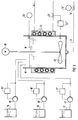
- FIG. 3 shows such a representation of the plant to be guided on the monitor 10.
- a reactor 14 is fed from the storage containers 15 to 17 via the pumps 15 'to 17'.
- the pumps 15 'to 17' are regulated by flow controllers 15 '' to 17 ''.
- the reactor mixture 18 is mixed by the stirrer 20 driven by the motor 19.
- the reactor mixture 18 flows out via the line 21 through the valve 14 '.
- the valve 14 ' is controlled by the discharge control 14' '.
- the diagram according to FIG. 3 also shows the temperature controller 22 ′′, which regulates the supply of hot water to the heating coils 22 via the valve 22 ′ in such a way that a predetermined temperature range is maintained in the reactor mixture 18.
- a level controller 23 is shown in the illustration according to FIG. 3, which, as a higher-level controller, specifies the desired values for the flow controllers 15 ′′ to 17 ′′ and the flow controller 14 ′′.
- a display according to FIG. 3, which can be a complete display of the entire system or just a partial section, on the monitor 10 of the control system 1 is quite common in automated processes.
- a representation as shown in FIG. 4 is also common. Here, for example, is the time course of setpoint w and Actual value x of one of the control loops of the reactor 14 is shown. 4, the control loop parameters are also shown on the screen in the control room 1.
- the location of the error can e.g. be implicitly given that the address of the automation device and the address of the module 5 'in which the error has occurred, or the identification of the electrical component 7', for. B. a circuit breaker in which the error has occurred is transmitted.
- the address or identification is initially only logical, i.e. not physically related to the actual location, e.g. the slot related.
- the actual fault location can only be determined by comparing the address or marking with the configuration data.
- the time at which the error occurred can either be determined by the operator control and monitoring system 1, or the time is also transmitted.
- the user of the system does not want to ignore the error message, but rather wants to localize the error more precisely, he enters a corresponding command on the terminal 11 in order to take a closer look at the geographical and the switching location of the error.
- the entry can e.g. the entry of the command "Control-S". If a mouse 12 is available to the user, it is particularly easy to call up the error analysis. In this case, the user only has to click on the field 24, which displays a special message, with the mouse 12. When the user calls the error display function, he next receives a display of the control cabinet 3 in which the error has occurred. This representation is shown in FIG. 5.
- the configuration data of the automation system are called up from the configuration data memory 13 by the processor 9.
- the processor 9 determines the control cabinet 3 in which the error occurred and its geometric structure. This structure is shown in FIG. 5 when the error representation program is called up on monitor 10.
- the number, and possibly also the location of the control cabinet 3, is displayed in the display field 25.
- FIG. 6 the number of the control cabinet 3 and that of the subrack 4 which is shown is now shown on the monitor 10 in the display field 25.
- the illustration of the subrack 4 is as in FIG. 5.
- the subassemblies 5 are again shown here, the defective assembly 5 'being optically highlighted.
- the geographical location of the error namely the assembly 5 '
- the illustration according to FIG. 6 is conclusive.
- the user can also be informed of the switching location of the fault in addition to the geographical location.
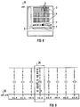
- FIG. 7 shows the part of the circuit diagram in which the fault occured.
- the circuit diagram was also determined by the processor 9 using the configuration data from the configuration data memory 13.
- the display panel 25 shows the numbers of control cabinet 3, subrack 4, assembly 5 'and the side of the circuit diagram.
- the circuit diagram of this page is also shown on the monitor 10.
- the location of the fault, this time in terms of switching technology, is optically highlighted, e.g. by flashing the border 26.
- a message about the type of error can be made on the monitor 10.
- the error detection in the automation system must be carried out so precisely that every error can be precisely localized. It is therefore not sufficient to simply recognize an error, but at least the error code and the address or the identification of the component in which the error occurred must be transmitted.
- FIG 8 which also shows the representation of the overall control cabinet 3, an error in the electrical component 7 'has been detected. If the electrical component 7 'itself cannot transmit a message to the operator control and monitoring system 1, this must take place indirectly via an automation device which then reports this error to the operator control and monitoring system 1.
- a signal which is triggered by the electrical component 7 'in the event of an error is used as the input signal of an automation device, the automation device being programmed such that it reports this error to the operator control and monitoring system 1 when the error signal is present.
- This error is also displayed on the monitor 10 after the configuration data has been called up by the processor 9.
- the display follows as before for the defective assembly 5 'by visual highlighting. The geographical location of the error is therefore sufficiently localized.
- the part of the circuit diagram of this electrical component 7' in which the error has occurred is again displayed on the monitor 10.
- the error is again, e.g. by means of the flashing border 26, optically highlighted.
- configuration data also contains the programs for the individual parts of the automation system, it is of course also possible to detect and display program errors (e.g. limit violation of a software controller or timeout of an execution level).
- the fault localization and the fault diagnosis from the control room 1 is made considerably easier by means of the monitoring method described above.
- a data memory e.g. a hard disk
- the advantage of the invention lies in the rapid localization of the fault location from the control room. In addition, it is no longer necessary to search laboriously in paper manuals.
- the monitoring process can of course not only take place in the control room, but in principle from any computer that has a graphics-capable monitor and access to the configuration data. It is e.g. It is possible to connect the control cabinets 3 to one another via a local area network (LAN) and to provide options for connecting a graphics-capable programming device to the local area network. Then when the configuration data, e.g. the method can of course also be carried out by means of the programming device by means of a floppy disk which is available to the programming device.
- LAN local area network
Landscapes
- Engineering & Computer Science (AREA)
- Human Computer Interaction (AREA)
- Physics & Mathematics (AREA)
- General Physics & Mathematics (AREA)
- Automation & Control Theory (AREA)
- Testing And Monitoring For Control Systems (AREA)
- Analysing Materials By The Use Of Radiation (AREA)
- Debugging And Monitoring (AREA)
Applications Claiming Priority (2)
| Application Number | Priority Date | Filing Date | Title |
|---|---|---|---|
| DE4210420 | 1992-03-30 | ||
| DE4210420A DE4210420C2 (de) | 1992-03-30 | 1992-03-30 | Überwachungsverfahren für einen technischen Prozeß |
Publications (3)
| Publication Number | Publication Date |
|---|---|
| EP0563684A2 true EP0563684A2 (fr) | 1993-10-06 |
| EP0563684A3 EP0563684A3 (en) | 1995-09-06 |
| EP0563684B1 EP0563684B1 (fr) | 1999-01-13 |
Family
ID=6455440
Family Applications (1)
| Application Number | Title | Priority Date | Filing Date |
|---|---|---|---|
| EP93104363A Expired - Lifetime EP0563684B1 (fr) | 1992-03-30 | 1993-03-17 | Procédé de surveillance et système d'observation pour un processus technique |
Country Status (5)
| Country | Link |
|---|---|
| US (1) | US6031453A (fr) |
| EP (1) | EP0563684B1 (fr) |
| AT (1) | ATE175788T1 (fr) |
| CA (1) | CA2092880C (fr) |
| DE (2) | DE4210420C2 (fr) |
Cited By (3)
| Publication number | Priority date | Publication date | Assignee | Title |
|---|---|---|---|---|
| US6460070B1 (en) | 1998-06-03 | 2002-10-01 | International Business Machines Corporation | Mobile agents for fault diagnosis and correction in a distributed computer environment |
| WO2004025383A3 (fr) * | 2002-08-29 | 2004-12-23 | Krones Ag | Procede, dispositif et systeme pour afficher les donnees d'un systeme de commande de machine |
| EP1333552A3 (fr) * | 2002-01-31 | 2006-05-03 | Siemens Aktiengesellschaft | Procédé et appareil pour la détection de conditions des défauts dans l'alimentation d'une charge |
Families Citing this family (23)
| Publication number | Priority date | Publication date | Assignee | Title |
|---|---|---|---|---|
| DE4332874A1 (de) * | 1993-09-27 | 1995-03-30 | Siemens Nixdorf Inf Syst | Verfahren zur Überwachung von Materialflußprozessen in der Fertigung |
| US5548715A (en) * | 1994-06-10 | 1996-08-20 | International Business Machines Corporation | Analysis of untestable faults using discrete node sets |
| DE4438859C2 (de) * | 1994-11-02 | 1996-12-12 | Siemens Ag | Verfahren zur Analyse von Prozeßdaten einer technischen Anlage |
| DE29610058U1 (de) * | 1996-06-07 | 1996-08-29 | Schimitzek, Peter, Dr., 52511 Geilenkirchen | Anordnung zur Integration von betriebswirtschaftlichen heterogenen Kennwerterfassungseinheiten von für die Gütererstellung benötigten Kenngrößen und zur Steuerung der Gütererstellung |
| DE19805518B4 (de) * | 1998-02-11 | 2013-10-24 | Siemens Aktiengesellschaft | Verfahren und Vorrichtung zur Analyse von Schutzsignalen für eine Anzahl von sicherheitsrelevanten Anlagenteilen einer technischen Anlage |
| DE19850969A1 (de) * | 1998-11-05 | 2000-05-31 | Basler Ag | Verfahren zum Anzeigen der Fehlerhäufigkeit und der Fehlerfrequenz bei einem taktweise arbeitenden Fehlerinspektionssystem |
| DE19903826B4 (de) * | 1999-02-02 | 2006-03-30 | Daimlerchrysler Ag | System zur Überwachung einer Fertigungsanlage |
| DE19911309B4 (de) * | 1999-03-13 | 2006-11-09 | Rittal Gmbh & Co. Kg | Schaltschranküberwachungseinrichtung |
| PT1261897E (pt) | 2000-02-25 | 2005-02-28 | Siemens Ag | Processo para operar e dispositivo para monitorar uma instalacao tecnica |
| FI20001341A7 (fi) * | 2000-06-05 | 2002-01-28 | Metso Paper Automation Oy | Menetelmä prosessinohjausjärjestelmässä ja prosessinohjausjärjestelmä |
| DE10052996C2 (de) * | 2000-10-18 | 2003-03-20 | Demag Ergotech Wiehe Gmbh | Spritzgießeinrichtung mit mindestens zwei Steuerungen |
| JP4474814B2 (ja) * | 2001-09-05 | 2010-06-09 | 三菱電機株式会社 | 監視システム |
| CA2579675A1 (fr) * | 2004-09-10 | 2006-03-23 | Cooper Technologies Company | Systeme et procede pour le controle et la gestion de protecteurs de circuits |
| DE102006010686B4 (de) * | 2006-03-08 | 2010-04-01 | Rittal Gmbh & Co. Kg | Anordnung mit mindestens einem Schaltschrank und/oder Rack |
| US9374242B2 (en) * | 2007-11-08 | 2016-06-21 | Invention Science Fund I, Llc | Using evaluations of tentative message content |
| US8682982B2 (en) * | 2007-06-19 | 2014-03-25 | The Invention Science Fund I, Llc | Preliminary destination-dependent evaluation of message content |
| US8984133B2 (en) * | 2007-06-19 | 2015-03-17 | The Invention Science Fund I, Llc | Providing treatment-indicative feedback dependent on putative content treatment |
| US20080320088A1 (en) * | 2007-06-19 | 2008-12-25 | Searete Llc, A Limited Liability Corporation Of The State Of Delaware | Helping valuable message content pass apparent message filtering |
| US8082225B2 (en) * | 2007-08-31 | 2011-12-20 | The Invention Science Fund I, Llc | Using destination-dependent criteria to guide data transmission decisions |
| US8065404B2 (en) * | 2007-08-31 | 2011-11-22 | The Invention Science Fund I, Llc | Layering destination-dependent content handling guidance |
| US7930389B2 (en) * | 2007-11-20 | 2011-04-19 | The Invention Science Fund I, Llc | Adaptive filtering of annotated messages or the like |
| DE102008059713A1 (de) | 2008-11-29 | 2010-06-24 | Rittal Gmbh & Co. Kg | Anlage mit Schaltschränken oder Racks |
| US10152039B2 (en) | 2011-11-11 | 2018-12-11 | Rockwell Automation Technologies, Inc. | Method and apparatus for the display of multiple errors on a human-machine interface |
Family Cites Families (13)
| Publication number | Priority date | Publication date | Assignee | Title |
|---|---|---|---|---|
| DE3224586A1 (de) * | 1982-07-01 | 1984-01-05 | Bayerische Motoren Werke AG, 8000 München | Betriebsdatenerfassungseinrichtung |
| US4588987A (en) * | 1983-09-13 | 1986-05-13 | International Business Machines Corp. | Display system for monitoring and alarm system |
| DE3504578C2 (de) * | 1985-02-11 | 1994-09-22 | Siemens Ag | Numerische Werkzeugmaschinensteuerung mit einem Bildsichtgerät zum Darstellen von Bedien- und Anzeigefunktionen |
| DD237282A1 (de) * | 1985-05-14 | 1986-07-09 | Polygraph Leipzig | Einrichtung zur anzeige, registrierung und auswertung von ursachen fuer maschinenstillstaende |
| US4816208A (en) * | 1986-02-14 | 1989-03-28 | Westinghouse Electric Corp. | Alarm management system |
| DD251106A1 (de) * | 1986-07-21 | 1987-11-04 | Polygraph Leipzig | Einrichtung zur anzeige und steuerung von maschinendaten |
| JPS6382843A (ja) * | 1986-09-25 | 1988-04-13 | Mitsubishi Electric Corp | 自動車用電子装置の故障診断装置 |
| JPH0832095B2 (ja) * | 1987-04-15 | 1996-03-27 | 中部電力株式会社 | プラント監視装置 |
| DD279551A1 (de) * | 1989-01-18 | 1990-06-06 | Robotron Elektronik | Verfahren zum bestimmen fehlerhafter bauelemente |
| DE3910718A1 (de) * | 1989-04-03 | 1990-10-04 | Siemens Ag | Ueberwachungsgeraet mit schaltvorrichtung |
| US5189394A (en) * | 1989-12-22 | 1993-02-23 | Grinell Asia Pacific Pty. Limited | Fire alarm display |
| US5327117A (en) * | 1991-03-22 | 1994-07-05 | Omron Corporation | Adaptive message display apparatus |
| US5297252A (en) * | 1991-05-07 | 1994-03-22 | Don Becker | Color graphics terminal for monitoring an alarm system |
-
1992
- 1992-03-30 DE DE4210420A patent/DE4210420C2/de not_active Expired - Fee Related
-
1993
- 1993-03-17 EP EP93104363A patent/EP0563684B1/fr not_active Expired - Lifetime
- 1993-03-17 AT AT93104363T patent/ATE175788T1/de not_active IP Right Cessation
- 1993-03-17 DE DE59309288T patent/DE59309288D1/de not_active Expired - Lifetime
- 1993-03-29 CA CA002092880A patent/CA2092880C/fr not_active Expired - Fee Related
- 1993-03-30 US US08/040,053 patent/US6031453A/en not_active Expired - Lifetime
Cited By (4)
| Publication number | Priority date | Publication date | Assignee | Title |
|---|---|---|---|---|
| US6460070B1 (en) | 1998-06-03 | 2002-10-01 | International Business Machines Corporation | Mobile agents for fault diagnosis and correction in a distributed computer environment |
| EP1333552A3 (fr) * | 2002-01-31 | 2006-05-03 | Siemens Aktiengesellschaft | Procédé et appareil pour la détection de conditions des défauts dans l'alimentation d'une charge |
| WO2004025383A3 (fr) * | 2002-08-29 | 2004-12-23 | Krones Ag | Procede, dispositif et systeme pour afficher les donnees d'un systeme de commande de machine |
| US7761271B2 (en) | 2002-08-29 | 2010-07-20 | Krones Ag | Method, device and system for displaying data of a machine control system |
Also Published As
| Publication number | Publication date |
|---|---|
| EP0563684B1 (fr) | 1999-01-13 |
| DE4210420C2 (de) | 1997-02-13 |
| DE4210420A1 (de) | 1993-10-07 |
| CA2092880C (fr) | 2001-01-16 |
| ATE175788T1 (de) | 1999-01-15 |
| EP0563684A3 (en) | 1995-09-06 |
| CA2092880A1 (fr) | 1993-10-01 |
| DE59309288D1 (de) | 1999-02-25 |
| US6031453A (en) | 2000-02-29 |
Similar Documents
| Publication | Publication Date | Title |
|---|---|---|
| EP0563684A2 (fr) | Procédé de surveillance et système d'observation pour un processus technique | |
| DE4317729A1 (de) | Programmierbare Steuereinheit | |
| EP2430504B1 (fr) | Système de gestion d'alarme | |
| EP2221696A1 (fr) | Procédé et dispositif de contrôle d'un programme de commande d'une installation industrielle | |
| EP0645711A1 (fr) | Procédé d'opération d'un dispositif d'affichage et dispositifs pour la mise en oeuvre de ce procédé | |
| EP2356527A2 (fr) | Commande de sécurité et procédé pour commander une installation automatisée comprenant une pluralité de composants matériels | |
| EP0658831A1 (fr) | Méthode pour le développement d'un système d'automatisation | |
| EP4370986B1 (fr) | Système de commande pour une installation technique à des vues réduites des images de l'installation | |
| EP3637211B1 (fr) | Procédé de fonctionnement d'une installation ainsi qu'une installation | |
| EP4099114B1 (fr) | Procédé de détection d'une commande restreinte et d'observation d'une installation technique, système de commande et d'observation et système de contrôle de processus | |
| EP1854055A1 (fr) | Systeme d'ingenierie | |
| EP1561172B1 (fr) | Dispositif offrant l'acces a des donnees | |
| DE4210844C2 (de) | Programmierbare Steuerung und Verfahren zur Überwachung eines Ablaufprogrammes für eine programmierbare Steuerung | |
| DE69311099T2 (de) | Verfahren und vorrichtung zur automatischen modifikation eines graphisches displays basierend auf einer steuerprogrammodifikation | |
| EP0645710A2 (fr) | Procédé de test du fonctionnement de mémoire non-faible au plan de la technique de la signalisation pour au moins deux canaux des données utiles stockées et agencement pour réaliser le procédé | |
| DE3603142A1 (de) | Vorrichtung und verfahren zum regeln und steuern von chemischen und physikalischen vorgaengen in einer vielzahl von dafuer geeigneten apparaten | |
| EP3779619A1 (fr) | Risques émergents d'un système technique | |
| EP4290326A1 (fr) | Système de commande pour une installation technique et procédé de fonctionnement | |
| EP2495693A1 (fr) | Procédé de traitement de flottes de chariots de manutention | |
| DE19752853C1 (de) | Verfahren und System zum Verarbeiten von Alarmmeldungen in einem Rechnerverbundnetz mit mehreren Personal Computern | |
| EP4607303A1 (fr) | Affichage de courbes de tendance critiques pendant la commande et l'observation | |
| EP4524669A1 (fr) | Procédé de commande et d'observation d'une installation technique à commander, système de commande et d'observation et système de commande de processus | |
| EP4478137A1 (fr) | Système de guidage pour une installation technique | |
| EP4685594A1 (fr) | Gestion d'alarme holistique pour un système de commande d'une installation technique | |
| EP4462200A1 (fr) | Fragments d'images d'installations pour la commande et l'observation |
Legal Events
| Date | Code | Title | Description |
|---|---|---|---|
| PUAI | Public reference made under article 153(3) epc to a published international application that has entered the european phase |
Free format text: ORIGINAL CODE: 0009012 |
|
| AK | Designated contracting states |
Kind code of ref document: A2 Designated state(s): AT BE CH DE FR GB IT LI NL SE |
|
| PUAL | Search report despatched |
Free format text: ORIGINAL CODE: 0009013 |
|
| AK | Designated contracting states |
Kind code of ref document: A3 Designated state(s): AT BE CH DE FR GB IT LI NL SE |
|
| 17P | Request for examination filed |
Effective date: 19951006 |
|
| 17Q | First examination report despatched |
Effective date: 19970429 |
|
| GRAG | Despatch of communication of intention to grant |
Free format text: ORIGINAL CODE: EPIDOS AGRA |
|
| GRAG | Despatch of communication of intention to grant |
Free format text: ORIGINAL CODE: EPIDOS AGRA |
|
| GRAH | Despatch of communication of intention to grant a patent |
Free format text: ORIGINAL CODE: EPIDOS IGRA |
|
| GRAH | Despatch of communication of intention to grant a patent |
Free format text: ORIGINAL CODE: EPIDOS IGRA |
|
| GRAA | (expected) grant |
Free format text: ORIGINAL CODE: 0009210 |
|
| AK | Designated contracting states |
Kind code of ref document: B1 Designated state(s): AT BE CH DE FR GB IT LI NL SE |
|
| PG25 | Lapsed in a contracting state [announced via postgrant information from national office to epo] |
Ref country code: NL Free format text: LAPSE BECAUSE OF FAILURE TO SUBMIT A TRANSLATION OF THE DESCRIPTION OR TO PAY THE FEE WITHIN THE PRESCRIBED TIME-LIMIT Effective date: 19990113 Ref country code: IT Free format text: LAPSE BECAUSE OF FAILURE TO SUBMIT A TRANSLATION OF THE DESCRIPTION OR TO PAY THE FEE WITHIN THE PRE;WARNING: LAPSES OF ITALIAN PATENTS WITH EFFECTIVE DATE BEFORE 2007 MAY HAVE OCCURRED AT ANY TIME BEFORE 2007. THE CORRECT EFFECTIVE DATE MAY BE DIFFERENT FROM THE ONE RECORDED.SCRIBED TIME-LIMIT Effective date: 19990113 |
|
| REF | Corresponds to: |
Ref document number: 175788 Country of ref document: AT Date of ref document: 19990115 Kind code of ref document: T |
|
| REG | Reference to a national code |
Ref country code: CH Ref legal event code: NV Representative=s name: SIEMENS SCHWEIZ AG Ref country code: CH Ref legal event code: EP |
|
| REF | Corresponds to: |
Ref document number: 59309288 Country of ref document: DE Date of ref document: 19990225 |
|
| ET | Fr: translation filed | ||
| GBT | Gb: translation of ep patent filed (gb section 77(6)(a)/1977) |
Effective date: 19990407 |
|
| NLV1 | Nl: lapsed or annulled due to failure to fulfill the requirements of art. 29p and 29m of the patents act | ||
| PLBE | No opposition filed within time limit |
Free format text: ORIGINAL CODE: 0009261 |
|
| 26N | No opposition filed | ||
| PGFP | Annual fee paid to national office [announced via postgrant information from national office to epo] |
Ref country code: BE Payment date: 20010320 Year of fee payment: 9 |
|
| PGFP | Annual fee paid to national office [announced via postgrant information from national office to epo] |
Ref country code: SE Payment date: 20010322 Year of fee payment: 9 |
|
| REG | Reference to a national code |
Ref country code: GB Ref legal event code: IF02 |
|
| PG25 | Lapsed in a contracting state [announced via postgrant information from national office to epo] |
Ref country code: SE Free format text: LAPSE BECAUSE OF NON-PAYMENT OF DUE FEES Effective date: 20020318 |
|
| PG25 | Lapsed in a contracting state [announced via postgrant information from national office to epo] |
Ref country code: BE Free format text: LAPSE BECAUSE OF NON-PAYMENT OF DUE FEES Effective date: 20020331 |
|
| BERE | Be: lapsed |
Owner name: *SIEMENS A.G. Effective date: 20020331 |
|
| EUG | Se: european patent has lapsed |
Ref document number: 93104363.2 |
|
| PGFP | Annual fee paid to national office [announced via postgrant information from national office to epo] |
Ref country code: AT Payment date: 20040211 Year of fee payment: 12 |
|
| PGFP | Annual fee paid to national office [announced via postgrant information from national office to epo] |
Ref country code: CH Payment date: 20040607 Year of fee payment: 12 |
|
| PG25 | Lapsed in a contracting state [announced via postgrant information from national office to epo] |
Ref country code: AT Free format text: LAPSE BECAUSE OF NON-PAYMENT OF DUE FEES Effective date: 20050317 |
|
| PG25 | Lapsed in a contracting state [announced via postgrant information from national office to epo] |
Ref country code: LI Free format text: LAPSE BECAUSE OF NON-PAYMENT OF DUE FEES Effective date: 20050331 Ref country code: CH Free format text: LAPSE BECAUSE OF NON-PAYMENT OF DUE FEES Effective date: 20050331 |
|
| REG | Reference to a national code |
Ref country code: CH Ref legal event code: PL |
|
| PG25 | Lapsed in a contracting state [announced via postgrant information from national office to epo] |
Ref country code: DE Free format text: LAPSE BECAUSE OF NON-PAYMENT OF DUE FEES Effective date: 20111001 |
|
| PGFP | Annual fee paid to national office [announced via postgrant information from national office to epo] |
Ref country code: FR Payment date: 20120327 Year of fee payment: 20 |
|
| PGFP | Annual fee paid to national office [announced via postgrant information from national office to epo] |
Ref country code: GB Payment date: 20120312 Year of fee payment: 20 |
|
| PGFP | Annual fee paid to national office [announced via postgrant information from national office to epo] |
Ref country code: DE Payment date: 20120518 Year of fee payment: 20 |
|
| REG | Reference to a national code |
Ref country code: DE Ref legal event code: R071 Ref document number: 59309288 Country of ref document: DE |
|
| REG | Reference to a national code |
Ref country code: GB Ref legal event code: PE20 Expiry date: 20130316 |
|
| PG25 | Lapsed in a contracting state [announced via postgrant information from national office to epo] |
Ref country code: GB Free format text: LAPSE BECAUSE OF EXPIRATION OF PROTECTION Effective date: 20130316 Ref country code: DE Free format text: LAPSE BECAUSE OF EXPIRATION OF PROTECTION Effective date: 20130319 |