EP0563780A1 - Methode zur magnetischen Aufzeichnung und Wiedergabe - Google Patents
Methode zur magnetischen Aufzeichnung und Wiedergabe Download PDFInfo
- Publication number
- EP0563780A1 EP0563780A1 EP93104893A EP93104893A EP0563780A1 EP 0563780 A1 EP0563780 A1 EP 0563780A1 EP 93104893 A EP93104893 A EP 93104893A EP 93104893 A EP93104893 A EP 93104893A EP 0563780 A1 EP0563780 A1 EP 0563780A1
- Authority
- EP
- European Patent Office
- Prior art keywords
- magnetic
- heads
- circuit
- recording
- signal
- Prior art date
- Legal status (The legal status is an assumption and is not a legal conclusion. Google has not performed a legal analysis and makes no representation as to the accuracy of the status listed.)
- Granted
Links
Images


Classifications
-
- G—PHYSICS
- G11—INFORMATION STORAGE
- G11B—INFORMATION STORAGE BASED ON RELATIVE MOVEMENT BETWEEN RECORD CARRIER AND TRANSDUCER
- G11B5/00—Recording by magnetisation or demagnetisation of a record carrier; Reproducing by magnetic means; Record carriers therefor
- G11B5/48—Disposition or mounting of heads or head supports relative to record carriers ; arrangements of heads, e.g. for scanning the record carrier to increase the relative speed
- G11B5/52—Disposition or mounting of heads or head supports relative to record carriers ; arrangements of heads, e.g. for scanning the record carrier to increase the relative speed with simultaneous movement of head and record carrier, e.g. rotation of head
- G11B5/53—Disposition or mounting of heads on rotating support
- G11B5/531—Disposition of more than one recording or reproducing head on support rotating cyclically around an axis
- G11B5/534—Disposition of more than one recording or reproducing head on support rotating cyclically around an axis inclined relative to the direction of movement of the tape, e.g. for helicoidal scanning
-
- G—PHYSICS
- G11—INFORMATION STORAGE
- G11B—INFORMATION STORAGE BASED ON RELATIVE MOVEMENT BETWEEN RECORD CARRIER AND TRANSDUCER
- G11B5/00—Recording by magnetisation or demagnetisation of a record carrier; Reproducing by magnetic means; Record carriers therefor
- G11B5/48—Disposition or mounting of heads or head supports relative to record carriers ; arrangements of heads, e.g. for scanning the record carrier to increase the relative speed
- G11B5/56—Disposition or mounting of heads or head supports relative to record carriers ; arrangements of heads, e.g. for scanning the record carrier to increase the relative speed with provision for moving the head support for the purpose of adjusting the position of the head relative to the record carrier, e.g. manual adjustment for azimuth correction or track centering
-
- G—PHYSICS
- G11—INFORMATION STORAGE
- G11B—INFORMATION STORAGE BASED ON RELATIVE MOVEMENT BETWEEN RECORD CARRIER AND TRANSDUCER
- G11B5/00—Recording by magnetisation or demagnetisation of a record carrier; Reproducing by magnetic means; Record carriers therefor
- G11B5/02—Recording, reproducing, or erasing methods; Read, write or erase circuits therefor
Definitions
- the present invention relates to a magnetic recording and reproducing method for recording and reproducing signals by helical scan with a double azimuth head arrangement in such devices as 8-mm VTR's (video tape recorders) and R-DAT's (digital audio tape recorders).
- the so-called helical scan method is gradually replacing the conventional longitudinal recording method whereby signals are recorded by a fixed head onto the magnetic tape in its longitudinal direction.
- the helical scan method designed to meet today's demand for recording in ever-higher density, involves recording signals obliquely relative to the longitudinal direction of the tape by use of a head attached to a rotating drum.
- the helical scan method is attracting attention for its potential application in business-use notebook-size recorders.
- One prior art method proposed to prevent cross talk is as follows: two heads (A and B) are attached to the rotating drum. These heads are mounted so that they have a predetermined angle each relative to a reference line, one angle having the opposite polarity of the other (e.g., + ⁇ and - ⁇ , a counterclockwise and a clockwise angle respectively relative to the reference line). Where signals are recorded by use of the rotating drum having the two heads A and B with different mounting angles, the two heads scan the tape alternately.
- the gap direction of the heads A and B i.e., vector of the gap magnetic field
- the signals are recorded onto recording tracks at the azimuth angle formed by the two heads A and B.
- the scheme is supposed to offer normally reproduced signals with no cross talk.
- the helical scan-based systems use as their magnetic recording medium the so-called evaporated or coated type magnetic tapes.
- the evaporated tape is constituted by a base film, made illustratively of polyethylene terephtalate, coated with a magnetic layer.
- the magnetic layer comprises a metal or alloy magnetic substance (e.g., Co-Ni alloy) deposited direct onto the base film by plating or by known vacuum thin film forming techniques (e.g., vacuum evaporation, sputtering, ion plating).
- the coated magnetic tape is produced by applying a coating material on a base film, the coating material constituting the magnetic layer.
- the coating material is made from needle magnetic particles dispensed in a binder composed of an organic polymeric material.
- the needle magnetic particles include Co-clad gamma-ferrite magnetic particles or ferromagnetic particles (called metal magnetic particles) constituting a surface oxide layer.
- the cross talk phenomenon is prevented effectively by enlarging the difference in the gap direction tilt angle (i.e., azimuth angle) of each head relative to the longitudinal recording tracks on the tape.
- the greater the difference in azimuth angle the greater the gap direction difference between the heads A and B relative to the direction in which the magnetic particles are oriented. This leads to further deterioration of characteristics.
- a magnetic recording and reproducing method for recording and reproducing signals by helical scan with a double azimuth head arrangement containing two heads, one of the two heads having an azimuth angle of ⁇ A and the other having an azimuth angle of ⁇ B , wherein
- the magnetic recording medium for use with systems to which the invention applies includes the so-called evaporated type magnetic recording tapes.
- the magnetic tapes of this kind are made of a non-magnetic supporting structure covered with a ferromagnetic metal thin film deposited by known vacuum thin film forming techniques.
- the non-magnetic supporting structure constituting part of the above magnetic recording medium may be any of the materials currently used for this recording medium: polyesters such as polyethylene terephtalate; polyolefins such as polyethylene and polypropylene; cellulose derivatives such as cellulose triacetate, cellulose diacetate and cellulose acetate butyrate; vinyl resins such as polyvinylidene chloride; and polymeric materials made from plastic materials such as polyimide, polyamide and polycarbonate.
- the non-magnetic supporting structure may have its surface treated so as to develop fine bumps that are conducive to better control of the surface properties.
- the magnetic material for constituting the magnetic layer over the supporting structure may be any of known magnetic materials.
- Such materials include, and are not limited to, magnetic metals such as Fe, Co and Ni, as well as Fe-Co, Co-Ni, Fe-Co-Ni, Fe-Co-Cr, Co-Ni-Cr and Fe-Co-Ni-Cr.
- the metal magnetic thin film is formed by any of such known vacuum thin film forming techniques as evaporation, sputtering and ion plating.
- the oblique evaporation technique involves moving a non-magnetic supporting structure in a predetermined direction relative to the circumference of a cooling can, the surface of the magnetic supporting structure being subjected to a flow of vapor (of the evaporated magnetic material coming from an evaporation source).
- the incident angle of the vapor flow with respect to the surface of the non-magnetic supporting structure is preferably 40 degrees or more. If the incident angle of the vapor flow is less than 40 degrees, too many vertical components result in the produced film and deteriorate the magnetic property within the surface.
- the magnetic tapes of this kind are made of a non-magnetic supporting structure coated with a magnetic paint that serves as the magnetic layer.
- the non-magnetic supporting structure may be composed of, but not limited to, the same materials as those for use with the evaporated type magnetic recording tapes.
- the magnetic layer covering the non-magnetic supporting structure is constituted by a coat of the magnetic paint made from magnetic powder dispersed in a resin binder.
- the magnetic powder and the resin binder may be any of the currently available types but are not limited thereto.
- the magnetic powder may be composed of needle crystal magnetic particles such as ferromagnetic iron oxide particles, ferromagnetic chromium dioxide particles, ferromagnetic alloy particles and iron nitride particles.
- the ferromagnetic iron particles may be any of the types expressed by the general formula of FeOx where, x falls within the range of 1.33 ⁇ x ⁇ 1.50
- Copper (Co) may be added to these ferromagnetic iron oxide particles for coercive force enhancement. Copper-loaded organic iron comes broadly in two kinds: doped type and coated type.
- the particles of ferromagnetic chromium dioxide may be loaded with at least one of such materials as Ru, Sn, Te, Sb, Fe, Ti, V and Mn for coercive force enhancement.
- Ferromagnetic alloy powder may be made from any of Fe, Co, Ni, Fe-Co, Fe-Ni, Fe-Co-Ni, Co-Ni, Fe-Co-B, Fe-Co-Cr-B, Mn-Br, Mn-Al, and Fe-Co-V. These alloys may be loaded with any of such metal components as Al, Si, Ti, Cr, Mn, Cu and Zn so as to improve various properties.
- the resin binder may be any of such polymers as vinyl chloride, vinyl acetate, vinyl alcohol, vinylidene chloride, acrylic ester, methacrylate ester, styrene, butadiene and acrylonitrile; copolymers that combine two or more of the above polymers; as well as polyurethane resin, polyester resin, epoxy resin, and cellulose derivatives.
- a hydrophilic polar group such as carboxyl group, sulfonic group, sulfate group and phosphate ester group may be introduced into the resin binder so as to better disperse the magnetic particles therewithin.
- the magnetic recording medium thus produced is in tape form.
- the magnetic particles constituting the magnetic layer are arranged in the longitudinal direction of the tape.
- ⁇ A +20°
- ⁇ B -20°
- the gap direction of one head with respect to the magnetic particle orientation on the tape is different from the gap direction of the other head. This causes a difference to occur in reproduction output between the heads A and B, thereby deteriorating reproduction characteristics.
- the azimuth angles ⁇ A and ⁇ B differ from each other (
- the azimuth angle difference makes it possible to circumvent the reproduction output difference between the heads as experienced with the prior art.
- the azimuth angles ⁇ A and ⁇ B are angles formed in the gap direction by the heads A and B relative to their scanning direction during recording or reproduction.
- a positive (+) and a negative (-) azimuth angle occur in the counterclockwise and clockwise directions, respectively, with reference to the scanning direction of the two heads A and B.
- the azimuth angles are made different (
- should preferably be 30 degrees or less each in order to suppress the difference in reproduction output between the two heads and to obtain the highest possible reproduction output.
- the azimuth angles ⁇ A and ⁇ B may be established as required by simply selecting appropriate mounting angles of the heads A and B.
- the reproduction output from the heads A and B relies for its magnitude on the angle between the signal recording direction of the heads and the direction of the magnetic particle orientation over the magnetic recording medium. That is, the reproduction output decreases as the divergence of the signal recording direction from the direction of the magnetic particle orientation over the recording medium increases.
- ⁇ represents the angle (still angle) between the longitudinal direction of the magnetic recording medium and the scanning direction of the heads A and B
- the actual direction of signal recording by each of the heads A and a relative to the longitudinal direction of the recording medium is given as the sum of the still angle ⁇ and the azimuth angles ⁇ A and ⁇ B .
- the sums of the still angle ⁇ and the azimuth angles ⁇ A and ⁇ B for the two heads A and B are replaced with recording angles ⁇ A and ⁇ B , respectively.
- the difference in reproduction output between the two heads A and B is minimized by setting the recording angles ⁇ A and ⁇ B to 30 degrees or less each. That setting of the recording angles makes the actual signal recording direction of the heads A and B substantially the same as the direction of the magnetic particle orientation over the magnetic recording medium. This suppresses the difference in reproduction output between the heads A and B and thereby prevents the deterioration of picture quality and other characteristics.
- the azimuth angles of the two heads attached to the rotating head coincide with each other for signal recording by helical scan onto the magnetic recording medium.
- the two heads develop a difference therebetween in reproduction output because of their gap direction discrepancy relative to the direction of the magnetic particle orientation over the recording medium.
- the problem is solved, according to the invention, by establishing two different azimuth angles ⁇ A and ⁇ B for the two heads A and B.
- the direction of signal recording by each of the heads A and B relative to the longitudinal direction of the magnetic recording medium is determined by the sum of the still angle ⁇ and the azimuth angles ⁇ A and ⁇ B , the still angle being formed between the longitudinal direction of the magnetic recording medium and the scanning direction of the heads A and B.
- the actual signal recording direction of the heads A and B is made substantially the same as the direction of the magnetic particle orientation over the magnetic recording medium. This setting inhibits the difference in reproduction output between the heads A and B.
- FIG. 1 shows schematically how tracks are recorded by a double azimuth head arrangement having two heads of different mounting angles.
- the tracks accommodate signals recorded by helical scan on an evaporated type magnetic tape with its axis of easy magnetization positioned in the longitudinal direction.
- the signal recording operation by helical scan over the magnetic tape 101 involves causing the heads A and a to scan the tape obliquely relative to the longitudinal direction x of the tape.
- the extended direction of recorded tracks T A and T B by the heads A and B forms an angle ⁇ with respect to the longitudinal direction x of the tape (called the still angle ).
- Signals are recorded onto the tracks T A and T B at azimuth angles ⁇ A and ⁇ B depending on the mounting angles of the heads A and B.
- the signal recording directions ⁇ A and ⁇ B of the heads A and B relative to the longitudinal direction x of the tape are each given as the sum of the azimuth angles ⁇ A and ⁇ B and the still angle ⁇ (
- signals are recorded so that the angles of the signal recording directions ⁇ A and ⁇ B relative to the longitudinal direction x of the tape (i.e., recording angles ⁇ A and ⁇ B ) coincide with each other. This suppresses the difference in reproduction output between the heads A and B and thereby improves picture quality and other characteristics.
- Fig. 2 depicts a typical relationship between signal recording direction ⁇ and reproduction output.
- positive (+) and negative (-) angles occur counter-clockwise and clockwise relative to the longitudinal direction x of the tape, respectively.
- the reproduction output is maximized when the recording direction ⁇ coincides with the longitudinal direction x of the tape, i.e., with the direction of the magnetic particle orientation on the magnetic tape.
- the reproduction output degenerates as the angle between recording direction ⁇ and longitudinal direction x of the tape becomes closer to 90 degrees. It is thus clear that to ensure a high reproduction output requires making the recording direction ⁇ as close to the axis of easy magnetization of the magnetic tape as possible.
- an output deterioration of 4 dB is observed when the recording direction ⁇ has an angle of 180 degrees relative to the longitudinal direction x of the tape. This is because the axis of easy magnetization of the magnetic tape exists not only in the longitudinal direction thereof but also in the direction of the film thickness at a certain angle relative to the surface.
- the inventor examined the effects of tilted axes of easy magnetization relative to the film thickness using various magnetic tapes with their axes of easy magnetization set in different directions. For examination, signals were first recorded on the magnetic tapes so that the recording direction ⁇ would become 20 degrees. The tapes thus obtained were checked for reproduction output at a wavelength of 0.5 ⁇ m. The azimuth angle was set to zero (reproduction output was set to 0 dB for the signals recorded in the usual longitudinal direction). It was then observed that the reproduction output was -0.7 dB, -0.5 dB and -0.4 dB with magnetic tapes having the axis of easy magnetization in the film thickness direction at angles of 10, 30 and 50 degrees relative to the surface, respectively.
- the effects of the invention may be said to be significant when it is applied to magnetic tapes with their axis of easy magnetization set at 30 ⁇ 20 degrees relative to the tape surface.
- the inventor then proceeded to consider conditions for obtaining good reproduction output characteristics while suppressing the difference in reproduction output between the two heads mounted on the double azimuth head arrangement.
- This experiment utilized an evaporated type magnetic tape with its magnetic layer deposited by known oblique evaporation techniques.
- the axis of easy magnetization of the magnetic tape was positioned in the longitudinal direction of the tape and tilted at about 30 degrees relative to the surface.
- the azimuth angles ⁇ A and ⁇ B and still angle ⁇ of the heads A and B were varied for recording and reproduction by helical scan. With the recording angles ⁇ A and ⁇ B switched to different values, the magnetic tape was checked for reproduction output.
- Table 1 below.
- For reproduction an 8-mm VTR equipped with a rotating head 40 mm in outer diameter was used.
- the recording wavelength was set to 0.5 ⁇ m and cross talk to 1.0 ⁇ m.
- Table 1 the reproduction output values are relative values with reference to 0 dB obtained with the recording angle ⁇ B made to coincide with the longitudinal direction of the tape (by use of comparative example 2, to be described later).
- the azimuth angles ⁇ A and ⁇ B and still angle ⁇ of the heads A and B are established so that the recording angles ⁇ A and ⁇ B are each set to 30 degrees or less, the reproduction output difference between the heads A and B is reduced to 0.5 dB or less, and the reproduction output deterioration of the heads A and B is 1 dB or less which is a practically acceptable deterioration level.
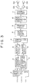
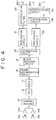
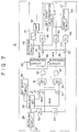
- the above-mentioned magnetic recording and reproducing method according to the invention provides excellent results (e.g., enhanced picture quality) when applied to systems such as the one described below.
Landscapes
- Television Signal Processing For Recording (AREA)
- Recording Or Reproducing By Magnetic Means (AREA)
- Digital Magnetic Recording (AREA)
Applications Claiming Priority (2)
| Application Number | Priority Date | Filing Date | Title |
|---|---|---|---|
| JP105368/92 | 1992-03-31 | ||
| JP10536892A JP3198607B2 (ja) | 1992-03-31 | 1992-03-31 | 磁気記録再生方法 |
Publications (2)
| Publication Number | Publication Date |
|---|---|
| EP0563780A1 true EP0563780A1 (de) | 1993-10-06 |
| EP0563780B1 EP0563780B1 (de) | 1997-06-04 |
Family
ID=14405776
Family Applications (1)
| Application Number | Title | Priority Date | Filing Date |
|---|---|---|---|
| EP93104893A Expired - Lifetime EP0563780B1 (de) | 1992-03-31 | 1993-03-24 | Methode zur magnetischen Aufzeichnung und Wiedergabe |
Country Status (5)
| Country | Link |
|---|---|
| US (1) | US5349478A (de) |
| EP (1) | EP0563780B1 (de) |
| JP (1) | JP3198607B2 (de) |
| KR (1) | KR100333418B1 (de) |
| DE (1) | DE69311186T2 (de) |
Families Citing this family (9)
| Publication number | Priority date | Publication date | Assignee | Title |
|---|---|---|---|---|
| MX9504078A (es) * | 1994-01-27 | 1997-06-28 | Loctite Ireland Ltd | Composiciones y metodos para proporcionar lineas conductoras anisotropica y enlaces entre dos conjuntos de conductores. |
| US5851644A (en) * | 1995-08-01 | 1998-12-22 | Loctite (Ireland) Limited | Films and coatings having anisotropic conductive pathways therein |
| US5916641A (en) * | 1996-08-01 | 1999-06-29 | Loctite (Ireland) Limited | Method of forming a monolayer of particles |
| US6402876B1 (en) | 1997-08-01 | 2002-06-11 | Loctite (R&D) Ireland | Method of forming a monolayer of particles, and products formed thereby |
| BR9706597A (pt) | 1996-08-01 | 1999-07-20 | Loctite Ireland Ltd | Processo para formação de uma monocamada de partículas e produtos formados desse modo |
| US6977025B2 (en) * | 1996-08-01 | 2005-12-20 | Loctite (R&D) Limited | Method of forming a monolayer of particles having at least two different sizes, and products formed thereby |
| JP2004227704A (ja) * | 2003-01-24 | 2004-08-12 | Sony Corp | ヘッド装置、記録再生装置及び磁気記録方法 |
| JP2005129201A (ja) * | 2003-10-02 | 2005-05-19 | Sony Corp | 磁気記録再生装置 |
| US9389854B2 (en) * | 2013-03-15 | 2016-07-12 | Qualcomm Incorporated | Add-compare-select instruction |
Citations (4)
| Publication number | Priority date | Publication date | Assignee | Title |
|---|---|---|---|---|
| US3925816A (en) * | 1968-07-10 | 1975-12-09 | Sony Corp | Magnetic recording system with overlapping tracks of high and low frequency information |
| GB2009995A (en) * | 1977-12-07 | 1979-06-20 | Grundig Emv | Recording and reproducing still pictures on video tape |
| GB2070841A (en) * | 1980-02-28 | 1981-09-09 | Oxby D V | Recording techniques |
| EP0229732A2 (de) * | 1986-01-16 | 1987-07-22 | Sony Corporation | Aufzeichnungs- oder Wiedergabegerät für longitudinale Aufzeichnung |
Family Cites Families (1)
| Publication number | Priority date | Publication date | Assignee | Title |
|---|---|---|---|---|
| JP3127530B2 (ja) * | 1991-10-29 | 2001-01-29 | ソニー株式会社 | 回転ヘッド装置 |
-
1992
- 1992-03-31 JP JP10536892A patent/JP3198607B2/ja not_active Expired - Lifetime
-
1993
- 1993-03-16 US US08/032,015 patent/US5349478A/en not_active Expired - Lifetime
- 1993-03-24 DE DE69311186T patent/DE69311186T2/de not_active Expired - Fee Related
- 1993-03-24 EP EP93104893A patent/EP0563780B1/de not_active Expired - Lifetime
- 1993-03-26 KR KR1019930004787A patent/KR100333418B1/ko not_active Expired - Fee Related
Patent Citations (4)
| Publication number | Priority date | Publication date | Assignee | Title |
|---|---|---|---|---|
| US3925816A (en) * | 1968-07-10 | 1975-12-09 | Sony Corp | Magnetic recording system with overlapping tracks of high and low frequency information |
| GB2009995A (en) * | 1977-12-07 | 1979-06-20 | Grundig Emv | Recording and reproducing still pictures on video tape |
| GB2070841A (en) * | 1980-02-28 | 1981-09-09 | Oxby D V | Recording techniques |
| EP0229732A2 (de) * | 1986-01-16 | 1987-07-22 | Sony Corporation | Aufzeichnungs- oder Wiedergabegerät für longitudinale Aufzeichnung |
Non-Patent Citations (2)
| Title |
|---|
| PATENT ABSTRACTS OF JAPAN vol. 10, no. 279 (E-439)20 September 1986 & JP-A-61 098 079 ( HITACHI LTD ) 16 May 1986 * |
| PATENT ABSTRACTS OF JAPAN vol. 12, no. 314 (E-649)25 August 1988 & JP-A-63 079 480 ( JVC LTD ) 9 April 1988 * |
Also Published As
| Publication number | Publication date |
|---|---|
| DE69311186D1 (de) | 1997-07-10 |
| DE69311186T2 (de) | 1997-09-25 |
| JPH05282601A (ja) | 1993-10-29 |
| KR930020371A (ko) | 1993-10-19 |
| US5349478A (en) | 1994-09-20 |
| JP3198607B2 (ja) | 2001-08-13 |
| EP0563780B1 (de) | 1997-06-04 |
| KR100333418B1 (ko) | 2002-08-19 |
Similar Documents
| Publication | Publication Date | Title |
|---|---|---|
| EP0483875B1 (de) | Verfahren und Gerät zur magnetischen Aufzeichnung von digitalen Videosignalen und magnetisches Aufzeichnungsmedium dafür | |
| US5247397A (en) | Method for magnetically recording digital video signals with specified ranges of the easy axis and the bias magnetic field | |
| US5492774A (en) | Perpendicular magnetic recording medium and process for production of the same | |
| EP0563780B1 (de) | Methode zur magnetischen Aufzeichnung und Wiedergabe | |
| US5512349A (en) | Method and apparatus for magnetic recording digital video signals and magnetic recording medium therefor | |
| EP0483873B1 (de) | Vorrichtung zur magnetischen Aufzeichnung von digitalen Daten | |
| US5384666A (en) | Digital picture signal recording apparatus in which a field interval is recorded in a plurality of tracks exhibiting a track pitch no greater than 5.5 μm by a rotary drum having a diameter no greater than 25 mm and a rotary speed no less than 150 rps | |
| US5906880A (en) | Magnetic recording medium | |
| JP3104364B2 (ja) | ディジタル画像信号の磁気記録方法 | |
| CA2073194C (en) | Magnetic recording apparatus of digital picture signal | |
| EP0488377B1 (de) | Magnetischer Aufnahmeträger und Verfahren zur magnetischen Aufnahme von analogen oder, vorzugsweise, digitalen Bildsignalen | |
| US5401572A (en) | Magnetic recording medium and magnetic recording method for digital image signal | |
| JP3030938B2 (ja) | 磁気記録媒体 | |
| JP3393491B2 (ja) | 垂直磁気記録媒体及びその製造方法 | |
| EP0576954B1 (de) | Verfahren zur magnetischen Datenaufzeichnung auf magnetisches Aufzeichnungsmedium. | |
| JPH0696434A (ja) | 磁気記録媒体及び磁気記録媒体の評価方法 | |
| JP3030972B2 (ja) | 磁気記録媒体の製造方法 | |
| JP3104097B2 (ja) | 磁気記録媒体の製造方法 | |
| JP3185314B2 (ja) | 磁気記録媒体の製造方法 | |
| JPH05174355A (ja) | 磁気記録媒体及びその製造方法 | |
| JPH05217166A (ja) | 磁気記録媒体の製造方法 | |
| JPH06150315A (ja) | 磁気記録媒体の製造方法 | |
| JPH0737238A (ja) | 磁気記録媒体 | |
| JPH064851A (ja) | 磁気記録媒体 | |
| JPH04295627A (ja) | ディジタル画像信号の磁気記録方法 |
Legal Events
| Date | Code | Title | Description |
|---|---|---|---|
| PUAI | Public reference made under article 153(3) epc to a published international application that has entered the european phase |
Free format text: ORIGINAL CODE: 0009012 |
|
| AK | Designated contracting states |
Kind code of ref document: A1 Designated state(s): DE FR GB |
|
| 17P | Request for examination filed |
Effective date: 19940309 |
|
| 17Q | First examination report despatched |
Effective date: 19950727 |
|
| GRAG | Despatch of communication of intention to grant |
Free format text: ORIGINAL CODE: EPIDOS AGRA |
|
| GRAG | Despatch of communication of intention to grant |
Free format text: ORIGINAL CODE: EPIDOS AGRA |
|
| GRAH | Despatch of communication of intention to grant a patent |
Free format text: ORIGINAL CODE: EPIDOS IGRA |
|
| GRAH | Despatch of communication of intention to grant a patent |
Free format text: ORIGINAL CODE: EPIDOS IGRA |
|
| GRAA | (expected) grant |
Free format text: ORIGINAL CODE: 0009210 |
|
| AK | Designated contracting states |
Kind code of ref document: B1 Designated state(s): DE FR GB |
|
| REF | Corresponds to: |
Ref document number: 69311186 Country of ref document: DE Date of ref document: 19970710 |
|
| ET | Fr: translation filed | ||
| PLBE | No opposition filed within time limit |
Free format text: ORIGINAL CODE: 0009261 |
|
| 26N | No opposition filed | ||
| REG | Reference to a national code |
Ref country code: GB Ref legal event code: IF02 |
|
| PGFP | Annual fee paid to national office [announced via postgrant information from national office to epo] |
Ref country code: FR Payment date: 20020312 Year of fee payment: 10 |
|
| PGFP | Annual fee paid to national office [announced via postgrant information from national office to epo] |
Ref country code: GB Payment date: 20020327 Year of fee payment: 10 |
|
| PGFP | Annual fee paid to national office [announced via postgrant information from national office to epo] |
Ref country code: DE Payment date: 20020404 Year of fee payment: 10 |
|
| PG25 | Lapsed in a contracting state [announced via postgrant information from national office to epo] |
Ref country code: GB Free format text: LAPSE BECAUSE OF NON-PAYMENT OF DUE FEES Effective date: 20030324 |
|
| PG25 | Lapsed in a contracting state [announced via postgrant information from national office to epo] |
Ref country code: DE Free format text: LAPSE BECAUSE OF NON-PAYMENT OF DUE FEES Effective date: 20031001 |
|
| GBPC | Gb: european patent ceased through non-payment of renewal fee |
Effective date: 20030324 |
|
| PG25 | Lapsed in a contracting state [announced via postgrant information from national office to epo] |
Ref country code: FR Free format text: LAPSE BECAUSE OF NON-PAYMENT OF DUE FEES Effective date: 20031127 |
|
| REG | Reference to a national code |
Ref country code: FR Ref legal event code: ST |