EP0564156B1 - Procédé et dispositif pour synthétiser le diamant en phase vapeur - Google Patents
Procédé et dispositif pour synthétiser le diamant en phase vapeur Download PDFInfo
- Publication number
- EP0564156B1 EP0564156B1 EP93302263A EP93302263A EP0564156B1 EP 0564156 B1 EP0564156 B1 EP 0564156B1 EP 93302263 A EP93302263 A EP 93302263A EP 93302263 A EP93302263 A EP 93302263A EP 0564156 B1 EP0564156 B1 EP 0564156B1
- Authority
- EP
- European Patent Office
- Prior art keywords
- cathode
- anode
- nozzles
- torch
- plasma
- Prior art date
- Legal status (The legal status is an assumption and is not a legal conclusion. Google has not performed a legal analysis and makes no representation as to the accuracy of the status listed.)
- Expired - Lifetime
Links
- 0 CC1C2C(C)(C)C(CC3)C(C)(C4)*3CC4C1CC(C)(C)C2 Chemical compound CC1C2C(C)(C)C(CC3)C(C)(C4)*3CC4C1CC(C)(C)C2 0.000 description 3
Images



Classifications
-
- C—CHEMISTRY; METALLURGY
- C23—COATING METALLIC MATERIAL; COATING MATERIAL WITH METALLIC MATERIAL; CHEMICAL SURFACE TREATMENT; DIFFUSION TREATMENT OF METALLIC MATERIAL; COATING BY VACUUM EVAPORATION, BY SPUTTERING, BY ION IMPLANTATION OR BY CHEMICAL VAPOUR DEPOSITION, IN GENERAL; INHIBITING CORROSION OF METALLIC MATERIAL OR INCRUSTATION IN GENERAL
- C23C—COATING METALLIC MATERIAL; COATING MATERIAL WITH METALLIC MATERIAL; SURFACE TREATMENT OF METALLIC MATERIAL BY DIFFUSION INTO THE SURFACE, BY CHEMICAL CONVERSION OR SUBSTITUTION; COATING BY VACUUM EVAPORATION, BY SPUTTERING, BY ION IMPLANTATION OR BY CHEMICAL VAPOUR DEPOSITION, IN GENERAL
- C23C16/00—Chemical coating by decomposition of gaseous compounds, without leaving reaction products of surface material in the coating, i.e. chemical vapour deposition [CVD] processes
- C23C16/22—Chemical coating by decomposition of gaseous compounds, without leaving reaction products of surface material in the coating, i.e. chemical vapour deposition [CVD] processes characterised by the deposition of inorganic material, other than metallic material
- C23C16/26—Deposition of carbon only
- C23C16/27—Diamond only
- C23C16/276—Diamond only using plasma jets
-
- C—CHEMISTRY; METALLURGY
- C23—COATING METALLIC MATERIAL; COATING MATERIAL WITH METALLIC MATERIAL; CHEMICAL SURFACE TREATMENT; DIFFUSION TREATMENT OF METALLIC MATERIAL; COATING BY VACUUM EVAPORATION, BY SPUTTERING, BY ION IMPLANTATION OR BY CHEMICAL VAPOUR DEPOSITION, IN GENERAL; INHIBITING CORROSION OF METALLIC MATERIAL OR INCRUSTATION IN GENERAL
- C23C—COATING METALLIC MATERIAL; COATING MATERIAL WITH METALLIC MATERIAL; SURFACE TREATMENT OF METALLIC MATERIAL BY DIFFUSION INTO THE SURFACE, BY CHEMICAL CONVERSION OR SUBSTITUTION; COATING BY VACUUM EVAPORATION, BY SPUTTERING, BY ION IMPLANTATION OR BY CHEMICAL VAPOUR DEPOSITION, IN GENERAL
- C23C16/00—Chemical coating by decomposition of gaseous compounds, without leaving reaction products of surface material in the coating, i.e. chemical vapour deposition [CVD] processes
- C23C16/44—Chemical coating by decomposition of gaseous compounds, without leaving reaction products of surface material in the coating, i.e. chemical vapour deposition [CVD] processes characterised by the method of coating
- C23C16/50—Chemical coating by decomposition of gaseous compounds, without leaving reaction products of surface material in the coating, i.e. chemical vapour deposition [CVD] processes characterised by the method of coating using electric discharges
- C23C16/513—Chemical coating by decomposition of gaseous compounds, without leaving reaction products of surface material in the coating, i.e. chemical vapour deposition [CVD] processes characterised by the method of coating using electric discharges using plasma jets
-
- H—ELECTRICITY
- H05—ELECTRIC TECHNIQUES NOT OTHERWISE PROVIDED FOR
- H05H—PLASMA TECHNIQUE; PRODUCTION OF ACCELERATED ELECTRICALLY-CHARGED PARTICLES OR OF NEUTRONS; PRODUCTION OR ACCELERATION OF NEUTRAL MOLECULAR OR ATOMIC BEAMS
- H05H1/00—Generating plasma; Handling plasma
- H05H1/24—Generating plasma
- H05H1/26—Plasma torches
- H05H1/32—Plasma torches using an arc
- H05H1/44—Plasma torches using an arc using more than one torch
Definitions
- This invention relates to a method and an apparatus of synthesizing diamond in vapor phase. Especially, it relates to a vapor phase method and apparatus which enable us to make a wide diamond of high quality in a short time in vapor phase.
- This invention is an improvement of the DC plasma jet method.
- Many proposals have been presented with regard to DC plasma jet methods. They have advantages and drawbacks in any way. Prior methods will be explained in short.
- a torch for plasma spraying was used for synthesizing diamond.
- a plasma torch has a cylindrical anode and a columnar cathode enclosed by the anode.
- a plasma jet is produced by the steps of applying a DC voltage between the cylindrical anode and the columnar cathode, supplying a carbon-containing gas, hydrogen gas and argon gas to a nozzle installed between the anode and the cathode, generating arc discharge, converting the gas into plasma and spurting the plasma with the discharge gas from the nozzle.
- This method utilizes untransferable, inner discharge.
- the gas for making plasma is a material gas including carbon itself. Namely, the gas to make plasma is not distinguished from the material gas.
- a material gas including carbon passes through a gap between the cathode and the anode.
- the nozzle ejects gases with so high speed that they form a jet flow. Furthermore, it utilizes hot plasma.
- the jet flow and the hot plasma allow the method to excel in high speed deposition.
- the method makes a carbon-containing gas flow through a gap between the anode and the cathode, surfaces of electrodes mainly near an outlet are likely to be covered with carbon deposition. Deposition of carbon makes the arc discharge unstable. Stable discharge cannot hold in the torch owing to the carbon deposition for a long time.
- this device would be insufficient to deposit diamond films with a wide area.
- Japanese Patent Laying Open No.64-33096 had proposed an improvement of forbidding the carbon containing gas from flowing through an inner space of a plasma torch. Namely, such a gas without carbon flows in the nozzle and a carbon containing gas is forced to blow to the plasma jet from a side of the plasma jet stream. Since carbon does not pass through the inner space of the torch, the inner space is immune from carbon contamination. Although this improvement would be effective for a small plasma jet with slow velocity, other problems remains for a big, rapid plasma jet. Large inertia of the big, rapid plasma flow will prevent a centripetal flow of a carbon-containing gas from attaining to the central part of the plasma jet. Thus, the carbon containing gas cannot be effectively dissolved and activated. The improvement fails in full exploitation of a carbon-containing gas.
- a torch has a cathode at the center.
- a bore is perforated in the cathode through which a carbon-containing gas is supplied in the torch.
- the surface of an anode or the cathode will not be contaminated by carbon.
- carbon will deposit on the gas outlet. The deposition of carbon will unstabilize the state of discharge. As the size of the outlet is so narrow, a little deposition of carbon easily changes the state of discharge.
- a DC arc plasma jet method excels in the speed of synthesis of diamond. Some report says that the method will exhibit a maximum deposition speed of 100 ⁇ m/h of diamond. In spite of the high speed of deposition, it is insufficient to produce a wide diamond film. If a wide diamond cannot be synthesized, objects of the diamond will be confined and production costs will be raised. Besides, it suffers from the instability of the state of discharge owing to carbon deposition on the surfaces of electrodes. Thus, drawbacks of DC plasma jet methods, i.e. a narrow deposition area, and instability of discharge have not been solved yet.
- a large plasma torch and big supply of power would enable us to obtain a wide diamond film.
- a single plasma torch produces only a small diamond film with a narrow area. Enlargement of a torch is ineffective owing to the instability of discharge and the restriction of cooling performance. Then plural plasma torches of the same structure aligned side by side would be effective, since a big plasma stream would be obtained by the confluence of individual plasma streams.
- Japanese Patent Laying Open No.1-172294 uses two equivalent torches aligned side by side. A bigger stream could be formed.
- this method combined two steams as it is.
- the density of plasma is not uniform but extremely irregular at the center or in the periphery. An irregular distribution of plasma in the combined stream will make a film with a large fluctuation in thickness or quality. Such an irregular film deposition resulted from primitive alignment of equivalent torches.
- Japanese Patent Laying Open No.61-259778 installs a pair of a plasma torch which will act as an anode and another plasma torch which will act as a cathode in a vacuum chamber. Each torch has a core cathode, a first outer electrode and a second outer electrode for anodes.
- inner plasma discharge is induced in individual torches by applying a DC voltage between the cathode and the anode of the individual ones. Then, the inner plasma discharge will be converted to an external plasma held between a torch as a cathode and another torch as an anode by the steps;
- This method allows the torches to form a wide, transferable, outer plasma jet instead of a narrow untransferable plasma jet which is kept between a cathode and an anode of the same torch.
- an arc occurring from a cathode of a cathode-torch passes through a nozzle between a first outer electrode and a second outer electrode of a cathode-torch, goes out from the torch, forms a hair-pin like arc-column and enters an anode point of an anode of an anode-torch.
- a beginning point on the cathode of the cathode-torch and an end point on the anode of the anode-torch of the transferable plasma jet are securely fixed. Fixation of the points stabilizes the arc column for a long time. Therefore, the instability of arc in the isolated, untransferable torch is resolved by the transferable jet.
- Japanese Patent Laying Open No.61-259779 has another feature. It has proposed a new torch having three electrodes, i.e. a central cathode, a first cylindrical anode and a second cylindrical anode which are coaxially disposed around the center line.
- Two separated spaces a space between the cathode and the first anode and another space between the first anode and the second anode, are provided for a torch.
- Gases can be supplied to both of two separated spaces. Namely, an inert gas will be let flow in the first space between the cathode and the first anode in the cathode-torch for protecting the inner cathode from plasma, when a transferable outer plasma column has been once established. Similarly the inert gas will be let flow in the second space between the first and second anodes for protecting the inner anode of the anode-torch from plasma.
- An outer plasma jet is formed among plural torches also in the invention. Features will be explained here ;
- Japanese patent Laying Open NO.2-248397 has succeeded in constructing a DC plasma jet apparatus in which carbon does not deposit on electrodes, an inert gas effectively protects anodes and cathodes and longterm, stable operation is realized by the improvements mentioned.
- the CVD method utilizes plural plasma torches which are disposed face to face each other. Some of the torches act as cathodes. The others play a role of anodes. All the torches are independent plasma torches with a cathode bar, anodes and a inherent power source. All torches can ignite inner arc plasma independently by applying a DC voltage between the electrodes from the individual power source. The arc plasma is untransferable, inner plasma.
- pairs of the inner plasma jets are coupled by assigning a torch as a cathode-torch and by assigning the other torch as an anode-torch.
- An outer plasma jet is produced between the cathode-torch and the anode-torch.
- the plasma jet is called an outer, transferable plasma arc jet.
- Individual plasma jets are integrated into a big unified plasma jet flame. Then the torches are relatively moved or rotated in order to enlarge the unified plasma jet flame.
- Such a dynamical enhancement of the plasma flame is a feature of the former invention.
- a wide plasma flame has enabled a plasma CVD method to make a wide diamond film on a wide substrate body at high speed. This was an excellent invention.
- the DC plasma jet method excels in high speed deposition but it cannot still conquer the difficulty of instability of discharge.
- Japanese Patent Laying Open No. 61-259778 and No. 2-248397 have resolved the requirement for longterm stability of plasma arc by replacing an untransferable, inner plasma arc by a transferable, outer plasma arc.
- EP-A-522 842 was an excellent method. However it has also drawbacks, because it uses bulky torches as anodes as well as cathodes for forming transferable plasma jets.
- the improvement produces outer, transferable plasma jets between cathode-torches and anode-torches, integrates the individual plasma jets into a unified plasma flame, and enlarges the plasma jet flame by rotating or moving the cathode-torches and the anode-torches.
- the method uses complete, full-functioning torches for producing and maintaining plasma arc jets. All members are genuine plasma torches. Some of the torches are assigned to cathodes. The other of the torches are assigned to anodes. In case of employing equivalent plasma torches, the roles for anode or cathode can be changed among them. All the torches can independently fire plasma jets.
- US-A-3714390 is a prior art document which describes the production of plasmas using a cathode blow pipe and a number of anode nozzles.
- An individual plasma torch has an cathode bar, plural outer electrodes ( anodes ) and a cooling device for the cathode bar.
- a cathode point which is a negative end point of an arc on the cathode bar shall be protected by argon gas from hot plasma.
- the plasma torch must have a double gas passageways structure. Therefore, the plasma torch is a very heavy, bulky and highly expensive apparatus.
- the large size of a front opening impedes the access to each other. The minimum distance between two torches is restricted by the large size. A considerable long distance prevents a pair of torches from making an outer transferable plasma jet easily, because an outer plasma is formed by bringing an inner plasma in contact with another inner plasma.
- a purpose of this invention is to provide a method and apparatus for synthesizing diamond with a wide area by utilizing a DC plasma jet method which is inherently superior in high speed of deposition. Another purpose of this invention is to provide a method and an apparatus for synthesizing diamond which is less expensive than the apparatus using plasma torches as anodes. Another purpose of this invention is to provide a method of synthesizing diamond which allows us to enlarge the size of plasma jet more freely than EP-A-522 842.
- This invention uses at least one plasma torch and plural nozzles in order to form outer transferable plasma arc jets.
- Plasma torches can fire a plasma arc independently.
- the plasma torches act as cathodes, when transferable plasma arcs are yielded. Therefore, the plasma torches are now called cathode-torches.
- nozzles are simple devices which cannot fire plasma by themselves.
- the nozzles act as anodes, when an outer transferable plasma arc is formed. Thus the nozzles are called anode-nozzles for clarifying the role.
- the plasma torches fire individual plasma arcs by applying a voltage between their inherent anodes and a cathode. This is called an untransferable, inner plasma arc.
- a plasma gas and a voltage are supplied to the nozzles.
- the voltage induces new discharge between the nozzles and the cathode-torches, since the nozzles are applied a positive voltage and the torches are applied a negative voltage.
- the discharge makes another plasma arc between the cathode-torches and the nozzles. Namely, the nozzles catch arc plasma from the seed plasma in the cathode-torches.
- This is called a transferable, outer plasma arc jet, because the plasma arc spans two parts.
- the number of the outer, transferable plasma arcs depends on the number of cathode-torches and anode-nozzles.
- all the transferable plasma arcs are integrated to an wider, unified plasma jet.
- the unified plasma jet will be enlarged by displacing or rotating the nozzles or torches. Such a dynamical enlargement is one of the most conspicuous features of this invention.
- One aspect of the present invention provides a method for synthesizing diamond by decomposing and activating a material gas by DC plasma generated by a DC voltage applied between an anode and a cathode of plasma torch and by spraying activated plasma on a substrate body comprising the steps of:
- Another aspect of the present invention provides an apparatus for synthesizing diamond by dissolving and activating a material gas by DC plasma generated by a DC voltage applied between an anode and a cathode of a plasma torch and by spraying activated plasma on a substrate body comprising:
- this invention makes transferable, outer plasma jets between torches and nozzles.
- a seed plasma is of course produced by a plasma torch, but the seed plasma ignites outer plasma arcs between the torch and the nozzles which are supplied with discharge gas and are applied a positive voltage.
- Such anode-nozzles have very simple structures. The anode-nozzles are inexpensive and light. They dispense with inherent power sources.
- the transferable plasma jets are associated in a wider plasma jet. Then, the associated, wide plasma jet is enlarged by displacing or rotating plasma torches and anode nozzles. Such a dynamical expansion of plasma jet is another one of the features of this invention.
- Electrodes of torches are fully immune from carbon deposition. A material gas containing carbon does not pass in the torches.
- a carbon-containing gas is spurted by the nozzles to the confluences of the plasma jets yielded by the cathode-torches and the plasma jets yielded by the anode-nozzles. Since sections of the plasma jets are not so large, the carbon-containing gas can be penetrated uniformly in the plasma jets. After the plasma jets have inhaled enough carbon, all plasma jets unite together into an associated jet. The associated jet is a wide jet which could not be obtained by any prior art.
- the number of nozzles for spurting a carbon-containing gas should be equal to the number of confluences of plasma jets from anode-nozzles and plasma jets from cathode-torches.
- the number M of cathode-torches is 1 and the number N of anode-nozzles is 3, the number of confluences is three.
- three gas supplying nozzles should be used preferably.
- the plasma jets make four confluences. It is desirable to provide four gas supplying nozzles for spurting a carbon-containing gas into the confluences.
- At least two gas supplying nozzles placed at symmetrical position are enough to spurt a carbon-containing gas into the plasma jets uniformly in general.
- this invention makes individual torches produce inner, untransferable discharge at first. Then, the inner, independent discharge is converted into outer, transferable plasma jets between the cathode-torches and the anode-nozzles by special operations. Finally, the plasma formation area is enlarged by displacing or rotating the anode-nozzles and the cathode-torches.
- Transferable, outer plasma jets between M plasma torches and N anode-nozzles can be formed by the following methods;
- sum of the cathode-torches and anode-nozzles is more than three (M + N ⁇ 3).
- transferable plasma jets will be formed by the following steps: In an initial disposition, extensions of central axis of cathode-torches meet favorably with extensions of central axes of anode-nozzles at a point. Namely, the anode-nozzles and the cathode-torches lie initially on two imaginary cones which face together at their tops. The distance between the anode-nozzles and the cathode-torches is short.
- inner, untransferable plasma jets are formed in individual cathode-torches by applying a (RF superposed) DC voltage between the outer electrodes ( anodes ) and the cathode bar of the same torches.
- transferable arc plasma jets between cathode-torches and anode-nozzles are formed by applying the DC voltage between pertinent electrodes of the torches.
- individual outer, transferable plasma jets are integrated in a unified plasma jet flame.
- the area of the plasma jet flame is widened by displacing or rotating the anodes or /and the torches. This invention features such dynamical widening of the plasma jet area.
- This invention features an inequality of M + N ⁇ 3 with regard to the number M of cathode-torches and the number N of anode-nozzles.
- the number of confluences of plasma jets from the cathode-torches and plasma jets from the anode-nozzles is at most MN in a good disposition.
- the inequality M + N ⁇ 3 signifies two or more than two confluences.
- this invention enlarges the plasma area by moving or rotating the torches. This is a dynamical increment of the plasma area. Geometric increment and dynamic increment characterize this invention. This invention allows us to synthesize a diamond film of a large area by spraying a wide plasma jet to a substrate body.
- This invention forbids a carbon-containing gas from passing through the passageways of torches.
- surfaces of electrodes of plasma torches are not contaminated by carbon deposition.
- Gas nozzles are provided near the confluences of plasma jets for spurting a carbon-containing gas to the confluences of the cathode-torch jets and anode-nozzle jets.
- the plasma torches are moved or rotated at the final stage for enlarging plasma jets.
- the displacement of torches accompany deviation of the confluences. Therefore, the nozzles for spurting a carbon-containing gas should be displaced according to the displacement of the confluences in order to spurt a carbon-containing gas to optimum spots in the plasma jets.
- Embodiments of this invention can use more than three plasma torches.
- An outer plasma jet is generated between the cathode of a cathode-torch and the anode of an anode-nozzle (first-outer electrode ).
- the number M of cathode-torches is not necessarily equal to the number N of anode-nozzles.
- the anode-nozzles should preferably be arranged at positions which are rotationally symmetric to the extension of the central axis of the cathode-torch and in which the extensions of central axes of the anode-nozzles meet at a point along the central axis of the cathode-torch.
- the cathode-torch and the anode-nozzles form N confluences.
- Gas supplying nozzles for spurting a carbon-containing gas or a carbon-hydrogen-containing gas to N confluences should be installed. This is a static disposition at an initial state.
- the number of gas supplying nozzles is N.
- the plasma jet area is enlarged by moving or rotating the anode-nozzles and the cathode-torch. Movement of the nozzles and the torch accompanies the displacement of confluences. Positions and directions of the gas supplying nozzles should be change in order to spurt a carbon-containing gas to optimum positions of the jets.
- the center line of the imaginary cones is z-axis in the case.
- the inclination angle of the cathode-torches to z-axis is denoted by ⁇ and the inclination angle of the anode-nozzles to z-axis is denoted by ⁇ .
- the centers of anode- and cathode-torches are represented by ; 1st cathode-torch P 1 (g sin ⁇ cos ⁇ , g sin ⁇ sin ⁇ , g cos ⁇ ) 1st anode-nozzle Q 1 (h sin ⁇ cos2 ⁇ , h sin ⁇ sin2 ⁇ , h cos ⁇ ) 2nd cathode-torch P 2 (g sin ⁇ cos3 ⁇ , g sin ⁇ sin3 ⁇ , g cos ⁇ ) 2nd anode-nozzle Q 2 (h sin ⁇ cos4 ⁇ , h sin ⁇ sin4 ⁇ , h cos ⁇ )
- M N
- M such a symmetric arrangement is desirable. Even if M ⁇ N, a symmetric arrangement can be available, when M and N have a large greatest common divisor.
- Mode 1 moves anode-nozzles in parallel along their axes for receding from origin 0 ( confluence of jets ), which corresponds to increase of h in Eqs.(2) to (4).
- Mode 2 which moves cathode-torches to the directions of receding from origin 0 corresponds to increase of g in Eq.(1).
- Mode 3 does not move anode-nozzles in parallel, but changes direction vectors by reducing ⁇ in Eqs.(6) to (8).
- Mode 4 changes angular parameters ⁇ or 2 ⁇ to ⁇ + ⁇ or 2 ⁇ + ⁇ , where ⁇ is a small angle. Besides the change of ⁇ , ⁇ may be reduced.
- the plasma jet area can be adjusted by the following parameters;
- Fig.1 is a schematic view of a first embodiment utilizing one cathode-torch and three anode-nozzles.
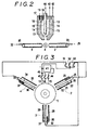
- Fig.2 is a side view of the cathode-torch and anode-nozzles only with the cathode-torch shown in section.
- Fig.3 is a sectional view of anode-nozzles with electric circuits for connecting torches and power sources.
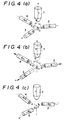
- Fig.4 is perspective views for demonstrating modes of rotation or displacement of anode-nozzles and cathode-torch for enhancing the plasma formation area.
- (a) shows an initial state
- (b) shows parallel transference of anode-nozzles and cathode-torch for receding from each other
- (c) shows rotations of anode-nozzles so as to induce discrepancy between extensions of anode-nozzles.
- Fig.5 is a schematic view of an apparatus of a second embodiment of this invention utilizing two cathode-torches and two anode-nozzles.
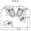
- Fig.6 is a sectional view of torches and nozzles with electric circuits for connecting torches and nozzles with power sources.
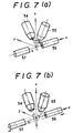
- Fig.7 is perspective views for demonstrating modes of displacement or rotation of anode-nozzles and cathode-torches for enhancing the plasma formation area.
- (a) shows an initial state
- (b) shows recession of anode-nozzles or rotation of cathode-torches.
- Fig.8 is a perspective view of an example of a flat anode-nozzles.
- Fig.9 is a sectional view of the anode-nozzles of Fig.8.
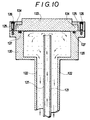
- fig.10 is a sectional view of a substrate body supported by a susceptor.
- Embodiment 1 uses one cathode-torch and three anode-nozzles.
- Fig. 1 demonstrates an apparatus for putting this invention into practice.
- a plasma torch and nozzles are shown in perspective manner for clarifying the relation of the torch and the nozzles.
- the plasma torch (1) has a cathode and anodes in coaxial relation therein which can yield plasma by generating arc discharge. Introducing gas into passageways from a rear end of the plasma torch, the torch excites the gas by arc discharge into plasma, and gushes a plasma jet from a front nozzle part.
- the torch (1) is used as a cathode when an outer, transferable plasma is formed.
- the plasma torch (1) is called a cathode-torch so as to clarify the function.
- Each anode-nozzle has a central electrode bar and a cylinder enclosing the electrode. Gas can be supplied into an inner space between the central electrode and the outer cylinder of each anode-nozzle.
- Set of gas supplying nozzles (5), (6) and (7) or another set of gas supplying nozzles (5'), (6') and (7') are installed around a plasma jet flame. Selection of an upper position or a lower position depends on the size of a plasma jet flame. If the plasma jet flame is less than 50 mm in diameter, the lower position of the nozzles should be selected. Lower-positioned gas nozzles (5'), (6') and (7') can uniformly inject a carbon-containing gas into the associated plasma jet flame, because the flame is still thin enough for the gas flow gushing from the sides.
- the upper position of the gas supplying nozzles should be chosen for injecting a carbon-containing gas into the confluences of plasma jets from the cathode- and anode-nozzles. At the confluences the plasma jet is still thinner than the associated plasma jet flame ( more than 50 mm ). Thus, carbon can be injected into an innermost position of the plasma jet. Once uniformly-distributed carbon will be redistributed uniformly in the associated flame.
- Fig.1 an upper set of gas supplying nozzles is shown by (5), (6) and (7).
- the gas supplying nozzle (5) faces to the confluence of the gases from the cathode-torch (1) and the anode-nozzle (2).
- the gas supplying nozzle (6) faces to the confluence of the gases from the cathode-torch (1) and the anode-nozzle (3).
- the gas supplying nozzle (7) corresponds to the last confluence of the gases from the cathode-torch (1) and the anode-nozzle (4).
- Outer, transferable plasma arcs (8) are produced between the cathode-torch (1) and the anode-nozzles (2), (3) and (4). Individual transferable plasma arcs are associated with a bigger plasma jet flame (8').
- the plasma torch (1), the anode-nozzles (2) to (4) and the gas supplying nozzles (5) to (7) or (5') to (7') are furnished in a vacuum chamber (9).
- the vacuum chamber (9) has a vacuum exhaust outlet (10) from which the chamber (9) can be made vacuous.
- a cooled susceptor (11) is installed below the plasma jet flame (8') in the vacuum chamber (9).
- a substrate body (12) is placed on the susceptor (11).
- a diamond film will be grown on the substrate body (12). Since the hot plasma jet flame (8') launches the substrate body (12), the susceptor (11) must be cooled. In the embodiment, the susceptor (11) is effectively cooled by water.
- Embodiment 1 has a cathode-torch (1) lying on z-axis, three anode-nozzles (2), (3) and (4) furnished at positions 3-fold rotationally symmetric around z-axis with a center angle of 120° .
- Inclination angle ⁇ of the anode-nozzles to z-axis is between 90° and 60° .
- a desirable range of the inclination angle ⁇ of the anode-nozzle is 10° to 110° .
- the central cathode-torch (1) is shown by a section view in order to demonstrate an inner structure of the cathode-torch (1).
- Fig. 3 demonstrates sections of the anode-nozzles (2), (3) and (4), and electric circuits for connecting a power source (41) to electrodes of the torch and the nozzles. Three anode-nozzles are equivalent nozzles.
- the cathode-torch (1) is larger than the anode-nozzles in weight and size.
- the cathode-torch (1) is a cylindrical device having three electrodes in coaxial relation; from outer to inner, a second outer electrode (13), a first outer electrode (14) and a cathode bar (15).
- the outer electrodes are assigned to anodes, when an Inner plasma is formed. These electrodes are separated by insulators.
- the cathode bar (15) is made from tungsten (W).
- the outer electrodes (13) and (14) are made from copper (Cu). In practice, these electrodes (13) and (14) have double walls between which cooling water flows to cool them.
- the cathode-bar (15) is cooled near its rear end.
- the first outer electrode (14)and the second outer electrode (13) taper away at a front end to be a narrow outlet.
- a first gas inlet (16) is provided by piercing a rear insulator of the cathode-torch (1) for introducing a gas (18) into a passageway between the cathode bar (15) and the first outer electrode (14).
- a second gas inlet (17) is provided by piercing the rear insulator in order to introduce a gas (19) into a passageway between the first outer electrode (14) and the second outer electrode (13).
- a gas (18) and another gas (19) are introduced into the passageways of the torch (1). These gases are gases for producing plasma.
- the anode-nozzles (2), (3) and (4) have a simpler structure than the cathode-torch (1) has.
- the anode-nozzle (2) is equipped with an insulator (20) at a rear end, a cylinder (21) and an anode bar (22) which are coaxially supported at rear ends by the insulator (20).
- a gas inlet (23) piercing a rear end of the insulator (24) introduces a gas (25) for producing plasma.
- the second anode-nozzle (3) is provided with an insulator (27) at a rear end, a cylinder (28) and an anode bar (29) which are held at rear ends by the insulator (27) in coaxial relation.
- a gas inlet (30) introduces a gas (32) for producing plasma through the insulator (27).
- the anode-nozzle (4) has an insulator (34) at a rear end, a cylinder (35) and an anode bar (36) which are held in coaxial relation at rear ends by the insulator (34).
- a gas (39) for exciting plasma is introduced from a gas inlet (37) piercing the insulator (34).
- the anode bars (22), (29) and (36) are made from copper (Cu).
- the copper anode bars have inner passages in which cooling water flows for cooling the copper anode bars.
- the anode-nozzles are strongly heated, since voltage is applied between the anode bars and the cathode-torch and an transferable plasma arc is formed therebetween.
- the outer cylinders (21), (28) and (35) are made from copper, they must be cooled.
- the voltage of the metal outer cylinders may be a floating level. If the outer cylinders are made from ceramics or high-melting point metals, they will dispense with cooling devices.
- the cathode-torch (a plasma torch) and the anode-nozzles (2), (3) and (4) let a gas flow in passageways between the cathode and the anode or between the anode bar and the outer cylinder for producing plasma jets.
- the gas is an inert gas or a mixture of an inert gas and hydrogen gas, where an inert gas means Ar, Ne, He or Kr. No carbon-containing gas flows in the cathode-torch (1) or the anode-nozzles (2),(3) and (4).
- the cathode-torch (1) is provided with a power source (41) which gives a DC voltage or a DC voltage superposed with an RF voltage to the electrodes of the torch. Superposition of RF voltage facilitates plasma arc generation.
- the anode-nozzles have no inherent power source.
- the power source (41) supplies an RF-superposed DC voltage between the cathode bar (15) and the first outer electrode (14) of the torch (1). Since the power source (41) is substantially a DC source, it has a positive pole ( denoted by + ) and a negative pole ( denoted by - ).
- the negative pole of the power source (41) is connected via a switch (44) to the cathode bar (15).
- the positive pole is connected via a switch (42) to the second outer electrode (13) and via a switch (43) to the first outer electrode (14).
- Double anodes ( outer electrodes ) of the cathode-torch (1) ensure that the inner plasma arc will be converted into an outer arc plasma and will facilitate the protection of electrodes by allowing a gas to flow in the passageway between the first and second outer electrodes. Therefore, two outer electrodes (13) and (14) are alternately applied with voltage by turning the switch (42) or (43) on or off.
- the anode-nozzles have no own power source individually but are connected to the positive electrode of the power source (41) through the switches (51), (52) and (53). Besides the torch, nozzles and power source, devices for supporting, displacing or rotating the cathode-torch, anode-nozzles and gas supplying nozzles are installed in the vacuum chamber but they are not shown in figures.
- the cathode torch (1) which is a plasma torch will produce an inner, untransferable plasma jet.
- the seed inner plasma will be converted to an outer, transferable plasma jet between the cathode-torch (1) and the anode-nozzles.
- the outer, transferable plasma jet will be enlarged.
- the torches and the switches as well as nozzles will be operated along with the following manners.
- the apparatus has three arc plasma flames, i.e. an outer plasma flame between the cathode-torch (1) and the anode-nozzle (2), another outer plasma flame between the cathode-torch (1) and the anode-nozzle (3), the other outer plasma flame between the cathode-torch (1) and the anode-nozzle (4).
- Embodiment 1 enables us to synthesize diamond at more than about 150 ⁇ m/h deposition speed on a 76mm (3 inch) diameter substrate.
- the fluctuation of film thinness is less than about 10 %.
- Raman scattering spectroscopy certifies that the synthesized film is a diamond of good quality without inclusion of non-diamond ingredients. This invention allows us to synthesize a good diamond with a wide area at a high speed.
- Fig.5 shows embodiment 2 which makes use of two cathode-torches (54) and (55) and two anode-nozzles (56) and (57).
- Plasma torches (54) and (55) are individually able to form inner untransferable plasma jets by ejecting plasma with discharge gases from gas outlets.
- the nozzles (56) and (57) cannot make a plasma arc by themselves.
- the torches (54) and (55) will act as cathodes.
- the plasma torches (54) and (55) are called cathode-torches in short.
- the nozzles (56) and (57) will act as anodes.
- the nozzles (56) and (57) are called anode-nozzles to clarifying the function.
- the anode-nozzles (56) and (57) are lighter and more facile to convey than the cathode-torches (54) and (55). Thus a simple device will be enough to support and convey the anode-nozzles. Furthermore, each anode-nozzle dispenses with an inherent power source.
- Gas supplying nozzles (58) and (59) supply a carbon-containing gas or a mixture gas of a carbon-containing gas and hydrogen gas to the confluences of outer arc plasma jets from the cathode-torches (54) and (55) and from the anode-nozzles (56) and (57).
- the cathode-torches (54) and (55), the anode-nozzles (56) and (57), the gas supplying nozzles (58) and (59) are installed in an upper space of the vacuum chamber (61) which can be made vacuous by a vacuum pump (not shown in figures ) through a gas outlet (62). Diamond will be synthesized under a reduced pressure or atmospheric pressure.
- a cooled susceptor (63) on which a substrate body (64) is fixed is furnished at lower part of the vacuum chamber (61). Cooling water circulates in an inner space of the susceptor (63) for cooling and protecting the substrate body against hot plasma jets.
- the cathode-torches (54) and (55) are disposed with front ends facing downward along slanting lines which meet at a point 0 (in Fig.7).
- the anode-nozzles (56) and (57) are aligned along a horizontal line which is parallel to the surface of the substrate (64).
- a vertical plane including the cathode-torches (54) and (55) is perpendicular to a vertical plane including the anode-nozzles (56) and (57).
- the direction of the anode-nozzles (56) and (57) is assigned to x-axis.
- the distance between the center of cathode-torches and the crossing point 0 ( an origin of the coordinate ) is denoted by g.
- cathode-torches (54) and (55) are simply expressed by cathode-torch (54) (0, g sin ⁇ , g cos ⁇ ) cathode-torch (55) (0, -g sin ⁇ , g cos ⁇ )
- a desirable inclination angle ⁇ of the cathode-torch is 0 to 45°.
- the directions of the cathode-torches (54) and (55) are designated by unit vectors; cathode-torch (54) ⁇ (0, -sin ⁇ , -cos ⁇ ) cathode-torch (55) ⁇ (0, sin ⁇ , -cos ⁇ )
- anode-nozzle 56) ⁇ (-1, 0, 0) anode-nozzle (57) ⁇ (+1, 0, 0)
- Fig.6 exhibits a sectional view of the cathode-torches, the anode-nozzles, and the electric circuit for connecting parts of the torches, nozzles and power sources.
- the torches have the same structure.
- the cathode-torches have inherent power sources, but the anode-nozzles have no own power source.
- the cathode-torch (54) has coaxially a second outer electrode (65), a first outer electrode (66) and a cathode bar (67).
- the cathode bar (67) is positioned at the center and is a tungsten bar ( W ) which is cooled at the rear end.
- the outer electrodes (65) and (66) are anodes which have double walls for letting cooling water passing through the inner space. Three electrodes are electrically separated by an insulator end plate.
- a gas inlet (68) pierces the rear wall for supplying a plasma formation gas (70) in a passageway between the central cathode bar (67) and the first outer electrode (66).
- Another gas inlet (69) pierces the rear wall for supplying a plasma formation gas (71) into a passageway between the second outer electrode (65) and the first outer electrode (66).
- the second cathode-torch (55) has a second outer electrode (72), a first outer electrode (73), a cathode bar (74) and gas inlets (75) and (76).
- Plasma formation gases (77) and (78) are introduced into passageways between the cathode bar (74) and outer electrodes (73) and (72) through the inlets (77) and (78).
- the anode-nozzle (56) has an insulator (79) at a rear end, an outer cylinder (80) and an anode-bar (81) supported by the insulator at the ends.
- a gas inlet (82) penetrating the rear insulator (79) introduces plasma formation gas into an inner space held between the cylinder (80) and the anode-bar (81).
- the anode-nozzle (57) has an insulator (86), an outer cylinder (87), an anode-bar (88) and a gas inlet (89).
- the insulator (86) supports the outer cylinder (87), the anode-bar (88) and the gas inlet (89) at the rear ends.
- Plasma formation gas (91) is introduced from the gas inlet (89).
- the anode-nozzles have no inherent power sources.
- the voltage of the outer cylinders (87) and (80) are a floating level. No plasma arc is produced between the cylinder (80) or (87) and the anode-bar (81) or (88) of the anode-nozzles.
- the first cathode-torch (54) is provided with a DC power source (93) which can superpose an RF voltage on a DC voltage.
- the negative pole of the power source (93) is connected to the cathode bar (67).
- Positive pole is connected via switches (94) and (105) to the first outer electrode (66) and the second outer electrode (65) respectively.
- the second cathode-torch (55) is provided with a DC power source (96) which can superpose an RF voltage on a DC voltage.
- the negative pole of the power source (96) is connected to the cathode bar (74).
- the positive pole is connected via switches (97) and (106) to the first outer electrode (73) and the second outer electrode (72) respectively.
- the anode bar (81) of the first anode-nozzle (56) is connected via a switch (100) to the positive pole of the power source (93) of the first cathode-torch (54).
- the anode bar (88) of the second anode-nozzle (57) is connected via a switch (103) to the positive pole of the power source (96) of the second cathode-torch (55).
- individual plasma torches (54) and (55) produce inner plasma arcs.
- an inert gas e.g. Ar, He, Ne, or Kr is let flow in the passageways between the cathode bars (67) and (74), and the first outer electrodes (66) and (73).
- diamond is synthesized on a molybdenum (Mo) substrate of a diameter of 127 mm (5 inches) under the conditions exhibited in TABLE 2.
- This invention enables us to synthesize a diamond film of 127 mm (5 inches) diameter on the molybdenum (Mo) substrate at a deposition speed higher than about 100 ⁇ m/h.
- the fluctuation of film thickness is less than about 15 % in spite of such a large width of 127 mm (5 inches).
- the diamond is superior in the uniformity of thickness.
- Raman scattering spectroscopy certifies that the diamond contains little impurities; non-diamond carbon ingredients.
- Embodiment 2 allows us to fabricate a wide diamond film of good quality at a high speed more than about 100 ⁇ m/h.
- Cylindrical anode-nozzles with an opening have been employed in the embodiments explained so far. However non-cylindrical anode-nozzles are also available. Further an anode-nozzle with plural openings is allowable.
- Fig.8 and Fig.9 demonstrate an example of a flat anode-nozzle.
- a flat anode-nozzle is preferable to cylindrical one for forming a transferable plasma arc toward a neighboring cathode-torch.
- a flat anode-nozzle enjoys another advantage that a wider plasma arc can be built up thereby.
- the anode-nozzle (110) comprises a flat rectangular casing (111) and an flat anode bar (112).
- the anode bar (112) has an inner way (113) for water.
- Gas passageways (114) are formed between the anode bar (112) and the casing (111).
- Two openings (115) are perforated at the front end of the casing (111).
- a cavity (116) is formed at the front of the anode bar (112).
- Two convex points (117) are formed at the front end of the anode bar (112) behind the openings (115). The convex points facile the occurrence of plasma and stabilize the plasma discharge, because they are surely assigned to be anode-points and suppress the probable fluctuation of the anode points.
- Enormous heat intake to a substrate accompanies the diamond synthesis by a DC arc plasma jet method.
- Effective cooling of a substrate is an important problem.
- the surface temperature of a substrate has an optimum range for diamond film formation. Allowable heat intake is determined by the performance of cooling device. Namely, the strength of the arc plasma is restricted by the power of the cooling device. The stronger arc plasma can activate, the more completely and faster the material gas and can synthesize diamond faster.
- Conventional method cooled a substrate e.g. by fixing a substrate tightly on a susceptor in favor of heat dissipation via susceptor. However, at least one boundary remains between a substrate and a susceptor. The boundary suppressed the heat conduction and restricted the cooling performance. This invention proposes a solution of the difficulty of cooling.
- FIG. 10 shows an advantageous mounting of a substrate.
- a susceptor (120) is an cylinder which lacks a top plane.
- An inner pipe (121) is disposed coaxially in a cylindrical susceptor column (122).
- a substrate (123) on which a diamond film will be deposited has an annular step (124).
- a ring (125) pressing the annular step (124) is fixed by screws (126) to the top periphery of the susceptor (120).
- An O-ring (128) is sandwiched between the substrate (123) and the susceptor (120).
- the substrate itself constructs a part of a susceptor. Coolant is introduced from the inner pipe (121) directly to the rear surface of the substrate (123). Direct contact of coolant to the substrate drastically enhances the cooling performance.
- Embodiment 1 succeeds in enhancing plasma electric power from 30 kW to 42 kW without any temperature rise by employing the cooling device shown in Fig. 10. Since the synthesis speed is in proportion to the intake power to plasma jets, the speed of synthesis is enhanced about by 50 %.
Landscapes
- Chemical & Material Sciences (AREA)
- Engineering & Computer Science (AREA)
- Plasma & Fusion (AREA)
- Physics & Mathematics (AREA)
- Metallurgy (AREA)
- General Chemical & Material Sciences (AREA)
- Chemical Kinetics & Catalysis (AREA)
- Materials Engineering (AREA)
- Mechanical Engineering (AREA)
- Organic Chemistry (AREA)
- Spectroscopy & Molecular Physics (AREA)
- Inorganic Chemistry (AREA)
- Crystals, And After-Treatments Of Crystals (AREA)
- Chemical Vapour Deposition (AREA)
Claims (20)
- Un procédé pour synthétiser du diamant en décomposant et en activant une matière gazeuse par un plasma à courant continu qui est produit par une tension continue appliquée entre une anode et une cathode d'une torche à plasma, et en pulvérisant le plasma activé sur un élément de substrat, comprenant les étapes suivantes :on dispose au moins une torche-cathode à plasma ayant une barre de cathode, des électrodes extérieures à titre d'anodes placées dans une relation coaxiale, et des passages de gaz formés entre la barre de cathode et les anodes extérieures, plusieurs buses-anodes ayant une barre d'anode et un cylindre extérieur, et des buses d'alimentation en gaz, dans une relation dans laquelle la torche-cathode et les différentes buses-anodes ne sont pas alignées sur une ligne droite, ni dirigées parallèlement les unes aux autres, mais qui est telle qu'un prolongement de la torche-cathode et des prolongements des buses-anodes se rencontrent en un point, la torche-cathode étant capable de décomposer et d'activer la matière gazeuse, la buse-anode étant capable d'éjecter un gaz, la buse d'alimentation en gaz étant capable de fournir la matière gazeuse sous la forme de jets, et les directions ou les positions de la torche-cathode et des buses-anodes étant réglables,on fait circuler dans les passages de gaz de la torche-cathode un gaz inerte ou un mélange d'un gaz inerte et d'hydrogène,on applique une tension continue à laquelle est superposée une tension RF, entre la barre de cathode et les anodes extérieures de la torche-cathode, pour induire une décharge entre elles,on produit dans la torche-cathode un jet de plasma d'arc intérieur, qui ne peut pas être transféré,on fait circuler un gaz inerte dans les buses-anodes,on amène les buses-anodes en contact avec le jet de plasma d'arc qui est produit par la torche-cathode,on égalise une tension de la barre d'anode des buses-anodes et une tension de l'électrode extérieure de la torche-cathode, pour appliquer la tension continue, sur laquelle est superposée une tension RF, entre les barres d'anode des buses-anodes et la barre de cathode de la torche-cathode,on isole les anodes extérieures de la torche-cathode vis-à-vis des buses-anodes,on forme des jets de plasma d'arc extérieurs, pouvant être transférés, entre les barres d'anode des buses-anodes et la barre de cathode de la torche-cathode, en capturant le jet de plasma d'arc intérieur dans la torche-cathode,on assemble les différents jets de plasma d'arc extérieurs, pouvant être transférés, en un jet de plasma intégré qui s'étend dans la région séparant la torche-cathode et les buses-anodes,on agrandit le plasma d'arc extérieur intégré, pouvant être transféré, en déplaçant ou en faisant tourner les buses-anodes et la torche-cathode,on émet sur les côtés du jet de plasma intégré des jets d'un gaz contenant du carbone ou d'un mélange d'hydrogène et d'un gaz contenant du carbone, à partir des buses d'alimentation en gaz,on pulvérise le jet de plasma intégré sur l'élément de substrat qui est positionné dans un chemin du jet de plasma, eton dépose sur l'élément de substrat du diamant synthétisé par réaction en phase vapeur.
- Un procédé selon la revendication 1, dans lequel les buses d'alimentation en gaz émettent des jets d'un gaz contenant du carbone ou d'un mélange d'hydrogène et d'un gaz contenant du carbone vers des régions de confluence des jets de plasma individuels qui sont formés entre la torche-cathode et les buses-anodes.
- Un procédé selon la revendication 1, dans lequel les buses d'alimentation en gaz peuvent être déplacées et tournées, et elles émettent des jets d'un gaz contenant du carbone ou d'un mélange d'hydrogène et d'un gaz contenant du carbone, vers des confluents des jets de plasma individuels qui sont formés entre la torche-cathode et les buses-anodes, lorsque des positions de confluence sont changées conformément au mouvement des buses-anodes et de la torche-cathode.
- Un procédé selon l'une quelconque des revendications 1 à 3, dans lequel on peut déplacer les buses-anodes le long de lignes droites, initialement un prolongement de la torche-cathode rencontre en un seul point des prolongements des buses-anodes, des extrémités avant de la torche-cathode et des buses-anodes sont placées aux points les plus proches, des arcs de plasma intérieurs, ne pouvant pas être transférés, sont amorcés dans la torche-cathode, des jets d'arc de plasma extérieurs, pouvant être transférés, sont amorcés entre la torche-cathode et les buses-anodes, et ensuite on déplace les buses-anodes dans des directions les écartant du point de rencontre O, dans le but d'agrandir le jet de plasma d'arc.
- Un procédé selon l'une quelconque des revendications 1 à 3, dans lequel on peut faire tourner les buses-anodes autour d'axes, initialement un prolongement de la torche-cathode rencontre en un seul point des prolongements des buses-anodes, des extrémités avant de la torche-cathode et des buses-anodes sont placées aux points les plus proches, des arcs de plasma intérieurs, ne pouvant pas être transférés, sont amorcés dans la torche-cathode, des jets d'arc de plasma extérieurs, pouvant être transférés, sont amorcés entre la torche-cathode et les buses-anodes, et ensuite on fait tourner les buses-anodes de façon à écarter les prolongements des buses-anodes du point de rencontre 0, afin d'agrandir le jet de plasma d'arc.
- Un procédé selon l'une quelconque des revendications 1 à 3, dans lequel on peut déplacer la torche-cathode le long de lignes droites, initialement un prolongement de la torche-cathode rencontre en un seul point des prolongements des buses-anodes, des extrémités avant de la torche-cathode et des buses-anodes sont placées aux points les plus proches, des arcs de plasma intérieurs, ne pouvant pas être transférés, sont amorcés dans la cathode-torche, des jets d'arc de plasma extérieurs pouvant êtree transférés sont amorcés entre la torche-cathode et les buses-anodes, et ensuite on déplace la torche-cathode dans des directions qui l'écartent du point de rencontre O, afin d'agrandir le jet de plasma d'arc.
- Un procédé selon l'une quelconque des revendications 1 à 3, dans lequel on fait tourner plusieurs torches-cathodes autour d'axes, initialement des prolongements des torches-cathodes se rencontrent en un seul point avec des prolongements des buses-anodes, des extrémités avant des torches-cathodes et des buses-anodes sont placées aux points les plus proches, des arcs de plasma intérieurs, ne pouvant pas être transférés, sont amorcés dans les torches-cathodes, des jets d'arc de plasma extérieurs, pouvant être transférés,, sont amorcés entre les torches-cathodes et les buses-anodes, et ensuite on fait tourner les torches-cathodes de façon que les prolongements des torches-cathodes s'écartent du point de rencontre O, dans le but d'agrandir le jet de plasma d'arc.
- Un procédé selon la revendication 1, dans lequel une torche-cathode et plus de deux buses-anodes sont installées, le substrat se trouve dans un prolongement de la torche-cathode, les buses-anodes sont disposées dans des positions symétriques en rotation par rapport au prolongement de la torche-cathode, des prolongements des buses-anodes passent à proximité du prolongement de la torche-cathode et des jets de plasma d'arc extérieurs peuvent être formés à des points symétriques en rotation entre la torche-cathode et l'ensemble de buses-anodes.
- Un procédé selon la revendication 8, dans lequel les buses-anodes s'étendent initialement dans un plan perpendiculaire au prolongement de la torche-cathode.
- Un procédé selon la revendication 8, dans lequel le jet de plasma intégré est agrandi en faisant reculer les buses-anodes et la torche-cathode à partir du point de rencontre O.
- Un procédé selon la revendication 8, dans lequel le jet de plasma intégré est agrandi en faisant tourner les buses-anodes et la torche-cathode de façon à permettre aux prolongements des buses-anodes et de la torche-cathode de s'écarter du point de rencontre O.
- Un procédé selon la revendication 1 ou la revendication 2, dans lequel plus de deux torches-cathodes et plus de deux buses-anodes sont installées dans des positions réciproques, des prolongements des torches-cathodes se rencontrent mutuellement en un seul point dans un état initial, des prolongements des buses-anodes se rencontrent mutuellement au point précité, les torches-cathodes sont placées à des points symétriques en rotation autour d'une normale à l'élément de substrat, les buses-anodes sont également placées à des positions symétriques en rotation autour de la normale, et des jets d'arc de plasma extérieurs, pouvant être transférés,sont formés entre les torches-cathodes et les buses-anodes.
- Un procédé selon la revendication 1 ou la revendication 2, dans lequel les buses d'alimentation en gaz émettent des jets d'oxygène en mélange avec un gaz contenant du carbone.
- Un appareil pour synthétiser du diamant en dissolvant et en activant une matière gazeuse par un plasma à courant continu qui est produit par une tension continue appliquée entre une anode et une cathode d'une torche à plasma, et en pulvérisant le plasma activé sur un élément de substrat, comprenant :une chambre à vide (9) dans laquelle on peut faire le vide ;une pompe à vide pour faire le vide dans la chambre à vide ;un support (11) pour supporter l'élément de substrat dans la chambre à vide ;au moins une torche-cathode (1) disposée dans la chambre à vide (9) et qui est conçue pour former un jet de plasma à courant continu pendant qu'elle est en utilisation, la torche-cathode comportant une barre de cathode (15), des électrodes extérieures (13, 14) à titre d'anodes, montées en position coaxiale autour de la barre de cathode (15), des passages entre la barre de cathode et les électrodes extérieures, et des entrées de gaz (18, 19) pour introduire un gaz dans les passages,un dispositif qui est conçu pour déplacer ou faire tourner la torche-cathode, pendant l'utilisation,un ensemble de buses-anodes ayant chacune une barre d'anode (22), un cylindre (21) entourant la barre d'anode et des entrées de gaz (25) pour introduire un gaz entre la barre d'anode et le cylindre,un dispositif qui est conçu pour déplacer ou faire tourner les buses-anodes, pendant l'utilisation,un ensemble de buses d'alimentation en gaz (4, 5, 6) qui sont conçues pour émettre, pendant l'utilisation, des jets d'un gaz contenant du carbone ou d'un mélange d'un gaz contenant du carbone et d'hydrogène, dans les jets de plasma qui sont éjectés par les torches-cathodes et les buses-anodes,un dispositif qui est conçu pour déplacer ou faire tourner les buses d'alimentation en gaz, pendant l'utilisation,des sources d'énergie (41) qui sont conçues pour fournir, pendant l'utilisation, une tension continue ou une tension continue sur laquelle est superposée une tension RF, entre la barre de cathode et l'électrode extérieure de la torche-cathode, ou entre les barres d'anodes des buses-anodes et la barre de cathode de la torche de cathode,des moyens pour connecter électriquement la torche-cathode et les buses-anodes aux sources d'énergie, etun ensemble d'interrupteurs (42, 43, 44 ; 51, 52, 53) incorporés dans la connexion électrique, et qui peuvent être utilisés, pendant l'utilisation, pour établir ou interrompre l'application de la tension à la torche-cathode ou aux buses-anodes,la configuration étant telle que, pendant l'utilisation, la torche-cathode est capable de former un plasma d'arc intérieur individuel, à partir du gaz introduit dans les passages, par l'application de la tension continue entre la barre de cathode et les électrodes extérieures à titre d'anodes, etn'importe lesquelles des buses-anodes peuvent former un jet de plasma extérieur, pouvant être transféré, avec une torche-cathode, par l'application de la tension continue entre la barre d'anode de la buse-anode et la barre de cathode de la torche-cathode.
- Un appareil selon la revendication 14, dans lequel plusieurs torches-cathodes (54, 55) sont disposées dans des positions symétriques en rotation autour d'une normale à l'élément de substrat, et de façon que des prolongements des torches-cathodes se rencontrent en un point O sur la normale, et que les angles entre les prolongements et la normale soient inférieurs à 45°, les buses-anodes (56, 57) sont disposées dans des positions symétriques en rotation par rapport à la normale, et de façon que des prolongements des buses-anodes se rencontrent au même point O sur la normale, et que les angles entre les prolongements et la normale soient restreints à une plage comprise entre 10 degrés et 110 degrés.
- Un appareil selon la revendication 14, dans lequel le nombre des torches-cathodes (54, 55) est égal au nombre des buses-anodes (56, 57), les torches-cathodes sont disposées dans des positions symétriques en rotation autour d'une normale à l'élément de substrat, et de façon que des prolongements des torches-cathodes se rencontrent en un point O sur la normale, et que les angles entre les prolongements et la normale soient inférieurs à 45°, les buses-anodes (56, 57) sont disposées dans des positions symétriques en rotation par rapport à la normale, et de façon que des prolongements des buses-anodes se rencontrent au même point O sur la normale, et que les angles entre les prolongements et la normale soient restreints à une plage comprise entre 10 degrés et 110 degrés, chaque buse-anode étant espacée de la même distance par rapport à deux torches-cathodes voisines, et les jets d'arc de plasma extérieurs, pouvant être transférés, étant maintenus entre les torches-cathodes voisines et les buses-anodes.
- Un appareil selon la revendication 14, dans lequel le support comprend un suscepteur (11) qui n'a pas de paroi supérieure, l'élément de substrat est ajusté sur le suscepteur sans fuite par une bague fixée au suscepteur par des vis, et l'élément de substrat est refroidi directement par un fluide de refroidissement.
- Un appareil selon la revendication 17, dans lequel le suscepteur (11) avec refroidissement peut être déplacé dans une direction verticale par une unité de commande numérique, la hauteur du suscepteur étant réglable par l'unité de commande numérique de façon à maintenir la même position par rapport à la flamme du jet de plasma pendant la formation d'une pellicule de diamant.
- Un appareil selon la revendication 14, dans lequel chaque buse-anode (2, 3, 4) comporte un cylindre extérieur (21), une barre d'anode (22), un isolateur (20) pour supporter la barre d'anode et le cylindre dans une relation coaxiale, et un passage d'entrée de gaz (25) pour introduire un gaz dans un espace compris entre la barre d'anode et le cylindre, le cylindre extérieur étant polarisé au niveau de la masse ou à un niveau flottant pendant l'utilisation, et la barre d'anode étant protégée contre le plasma chaud par un gaz inerte qui est aspiré.
- Un appareil selon la revendication 14, dans lequel chaque buse-anode comporte un corps rectangulaire plat et une électrode plate incorporée dans le corps, le corps comportant deux ouvertures à une extrémité avant, et l'électrode intérieure ayant deux parties convexes à une extrémité avant, derrière les ouvertures.
Applications Claiming Priority (2)
| Application Number | Priority Date | Filing Date | Title |
|---|---|---|---|
| JP10601692A JP3203754B2 (ja) | 1992-03-30 | 1992-03-30 | ダイヤモンドの製造法および製造装置 |
| JP106016/92 | 1992-03-30 |
Publications (2)
| Publication Number | Publication Date |
|---|---|
| EP0564156A1 EP0564156A1 (fr) | 1993-10-06 |
| EP0564156B1 true EP0564156B1 (fr) | 1996-07-03 |
Family
ID=14422865
Family Applications (1)
| Application Number | Title | Priority Date | Filing Date |
|---|---|---|---|
| EP93302263A Expired - Lifetime EP0564156B1 (fr) | 1992-03-30 | 1993-03-25 | Procédé et dispositif pour synthétiser le diamant en phase vapeur |
Country Status (5)
| Country | Link |
|---|---|
| US (2) | US5539176A (fr) |
| EP (1) | EP0564156B1 (fr) |
| JP (1) | JP3203754B2 (fr) |
| DE (1) | DE69303404T2 (fr) |
| ZA (1) | ZA932211B (fr) |
Families Citing this family (26)
| Publication number | Priority date | Publication date | Assignee | Title |
|---|---|---|---|---|
| FR2695944B1 (fr) * | 1992-09-24 | 1994-11-18 | Onera (Off Nat Aerospatiale) | Appareil de dépôt chimique en phase vapeur activé par un plasma micro-ondes. |
| US5721720A (en) * | 1994-12-28 | 1998-02-24 | Kabushiki Kaisha Toshiba | Optical recording medium recording pixel data as a compressed unit data block |
| US6009202A (en) * | 1994-12-28 | 1999-12-28 | Kabushiki Kaisha Toshiba | Image information encoding/decoding system |
| RU2075135C1 (ru) * | 1995-01-13 | 1997-03-10 | Акционерное общество Научно-производственная фирма "А3" | Установка для плазмоструйной обработки пластин |
| US5847357A (en) * | 1997-08-25 | 1998-12-08 | General Electric Company | Laser-assisted material spray processing |
| US6028283A (en) * | 1998-02-02 | 2000-02-22 | Addison Machine Engineering, Inc. | Assembly and method for welding |
| DE29805999U1 (de) * | 1998-04-03 | 1998-06-25 | Agrodyn Hochspannungstechnik GmbH, 33803 Steinhagen | Vorrichtung zur Plasmabehandlung von Oberflächen |
| CA2277394C (fr) * | 1998-09-09 | 2003-10-21 | Saint-Gobain Industrial Ceramics, Inc. | Systeme de depot chimique en phase vapeur par jet de plasma equipe de multiples tetes de distribution |
| US6262523B1 (en) * | 1999-04-21 | 2001-07-17 | The Regents Of The University Of California | Large area atmospheric-pressure plasma jet |
| US7435082B2 (en) * | 2000-02-11 | 2008-10-14 | Michael E. Jayne | Furnace using plasma ignition system for hydrocarbon combustion |
| US6289868B1 (en) * | 2000-02-11 | 2001-09-18 | Michael E. Jayne | Plasma ignition for direct injected internal combustion engines |
| US6423923B1 (en) | 2000-08-04 | 2002-07-23 | Tru-Si Technologies, Inc. | Monitoring and controlling separate plasma jets to achieve desired properties in a combined stream |
| US6706157B2 (en) * | 2001-09-12 | 2004-03-16 | Transarc Ltd. | Vacuum arc plasma gun deposition system |
| US7022937B2 (en) * | 2003-01-06 | 2006-04-04 | Matsushita Electric Industrial Co., Ltd. | Plasma processing method and apparatus for performing uniform plasma processing on a linear portion of an object |
| CN1965104A (zh) * | 2004-03-09 | 2007-05-16 | 埃克阿泰克有限责任公司 | 膨胀式热等离子沉积系统 |
| JP4449645B2 (ja) * | 2004-08-18 | 2010-04-14 | 島津工業有限会社 | プラズマ溶射装置 |
| EP1949406B1 (fr) * | 2005-10-05 | 2010-12-08 | PVA TePla AG | Procédé de gravure au plasma et chambre de gravure |
| US7547861B2 (en) * | 2006-06-09 | 2009-06-16 | Morten Jorgensen | Vortex generator for plasma treatment |
| US20070284342A1 (en) * | 2006-06-09 | 2007-12-13 | Morten Jorgensen | Plasma treatment method and apparatus |
| US7671294B2 (en) * | 2006-11-28 | 2010-03-02 | Vladimir Belashchenko | Plasma apparatus and system |
| US7977599B2 (en) * | 2007-10-19 | 2011-07-12 | Honeywell International Inc. | Erosion resistant torch |
| US8610024B1 (en) | 2008-02-05 | 2013-12-17 | Zybek Advanced Products, Inc. | Apparatus and method for producing a lunar agglutinate simulant |
| US8946584B2 (en) | 2011-05-26 | 2015-02-03 | Retro Systems, LLC | Angled cut height control system for a plasma arch torch |
| US8946583B2 (en) | 2011-05-26 | 2015-02-03 | Retro Systems, LLC | Angled cut height control system for a plasma arch torch |
| DE102013106315B4 (de) * | 2013-06-18 | 2016-09-15 | Fraunhofer-Gesellschaft zur Förderung der angewandten Forschung e.V. | Verfahren und Vorrichtung zum Erzeugen eines physikalischen Plasmas |
| CN110072324B (zh) * | 2019-04-29 | 2025-01-07 | 成都真火科技有限公司 | 一种无阴极等离子发生器 |
Family Cites Families (8)
| Publication number | Priority date | Publication date | Assignee | Title |
|---|---|---|---|---|
| FR1600278A (fr) | 1968-12-31 | 1970-07-20 | Anvar | |
| GB1493394A (en) * | 1974-06-07 | 1977-11-30 | Nat Res Dev | Plasma heater assembly |
| JPS6125978A (ja) * | 1984-07-16 | 1986-02-05 | バリユア・アシキアン | 回転流体変位装置 |
| JPH0622719B2 (ja) * | 1985-05-13 | 1994-03-30 | 小野田セメント株式会社 | 複ト−チ型プラズマ溶射方法及びその装置 |
| JPH01172294A (ja) * | 1987-12-28 | 1989-07-07 | Fujitsu Ltd | ダイヤモンドの気相合成方法 |
| DE3884653T2 (de) * | 1987-04-03 | 1994-02-03 | Fujitsu Ltd | Verfahren und Vorrichtung zur Gasphasenabscheidung von Diamant. |
| JPH01179789A (ja) * | 1988-01-12 | 1989-07-17 | Fujitsu Ltd | ダイヤモンドの気相成長方法と熱プラズマ堆積方法およびプラズマ噴射装置 |
| JPH02248397A (ja) * | 1989-03-20 | 1990-10-04 | Onoda Cement Co Ltd | ダイヤモンドの製造装置および製造方法 |
-
1992
- 1992-03-30 JP JP10601692A patent/JP3203754B2/ja not_active Expired - Fee Related
-
1993
- 1993-03-25 DE DE69303404T patent/DE69303404T2/de not_active Expired - Fee Related
- 1993-03-25 EP EP93302263A patent/EP0564156B1/fr not_active Expired - Lifetime
- 1993-03-29 ZA ZA932211A patent/ZA932211B/xx unknown
- 1993-03-30 US US08/040,366 patent/US5539176A/en not_active Expired - Lifetime
-
1994
- 1994-08-26 US US08/298,713 patent/US5481081A/en not_active Expired - Lifetime
Also Published As
| Publication number | Publication date |
|---|---|
| US5481081A (en) | 1996-01-02 |
| ZA932211B (en) | 1993-10-13 |
| JPH05279182A (ja) | 1993-10-26 |
| DE69303404D1 (de) | 1996-08-08 |
| US5539176A (en) | 1996-07-23 |
| DE69303404T2 (de) | 1996-11-14 |
| JP3203754B2 (ja) | 2001-08-27 |
| EP0564156A1 (fr) | 1993-10-06 |
Similar Documents
| Publication | Publication Date | Title |
|---|---|---|
| US5539176A (en) | Method and apparatus of synthesizing diamond in vapor phase | |
| US5538765A (en) | DC plasma jet CVD method for producing diamond | |
| US5120567A (en) | Low frequency plasma spray method in which a stable plasma is created by operating a spray gun at less than 1 mhz in a mixture of argon and helium gas | |
| US5560779A (en) | Apparatus for synthesizing diamond films utilizing an arc plasma | |
| KR910006784B1 (ko) | 다이어몬드 증착장치와 방법 | |
| US5683548A (en) | Inductively coupled plasma reactor and process | |
| JP3762233B2 (ja) | ラジカル蒸着のためのシャワーヘッド装置 | |
| EP0522842B1 (fr) | Procédé et dispositif pour synthétiser le diamant en phase vapeur | |
| GB2486781A (en) | A microwave plasma reactor for manufacturing synthetic diamond material | |
| JPH0478592B2 (fr) | ||
| RU2032765C1 (ru) | Способ нанесения алмазного покрытия из паровой фазы и устройство для его осуществления | |
| JP2003147534A (ja) | 金属膜作製装置 | |
| WO1993002787A1 (fr) | Procede de production de materiaux en poudre ultrafins | |
| US20040188019A1 (en) | Device for treating a surface of a substrate, and a plasma source | |
| US5266363A (en) | Plasma processing method utilizing a microwave and a magnetic field at high pressure | |
| JP3194810B2 (ja) | ダイヤモンドの製造方法及び装置 | |
| Hirata et al. | Enlargement of the diamond deposition area by one-cathode three-anode arc discharge plasma jet chemical vapour deposition | |
| JPH0775689B2 (ja) | 熱プラズマジェット発生装置 | |
| JP3180842B2 (ja) | ダイヤモンド膜の製造方法 | |
| JPH01286993A (ja) | ダイヤモンドの合成方法 | |
| JPH06100397A (ja) | ダイヤモンド膜の作製方法及び装置 | |
| JPH07101798A (ja) | ダイヤモンド膜製造装置およびダイヤモンド膜製造方法 | |
| JP2004027352A (ja) | 金属膜作製装置及び金属膜作製方法 | |
| JPH0747819B2 (ja) | プラズマフラッシュ蒸着方法および装置 | |
| JP3047488B2 (ja) | ダイヤモンド膜の製造装置および製造方法 |
Legal Events
| Date | Code | Title | Description |
|---|---|---|---|
| PUAI | Public reference made under article 153(3) epc to a published international application that has entered the european phase |
Free format text: ORIGINAL CODE: 0009012 |
|
| AK | Designated contracting states |
Kind code of ref document: A1 Designated state(s): DE FR GB |
|
| 17P | Request for examination filed |
Effective date: 19940308 |
|
| 17Q | First examination report despatched |
Effective date: 19950425 |
|
| GRAH | Despatch of communication of intention to grant a patent |
Free format text: ORIGINAL CODE: EPIDOS IGRA |
|
| GRAH | Despatch of communication of intention to grant a patent |
Free format text: ORIGINAL CODE: EPIDOS IGRA |
|
| GRAH | Despatch of communication of intention to grant a patent |
Free format text: ORIGINAL CODE: EPIDOS IGRA |
|
| GRAA | (expected) grant |
Free format text: ORIGINAL CODE: 0009210 |
|
| AK | Designated contracting states |
Kind code of ref document: B1 Designated state(s): DE FR GB |
|
| REF | Corresponds to: |
Ref document number: 69303404 Country of ref document: DE Date of ref document: 19960808 |
|
| ET | Fr: translation filed | ||
| PLBE | No opposition filed within time limit |
Free format text: ORIGINAL CODE: 0009261 |
|
| STAA | Information on the status of an ep patent application or granted ep patent |
Free format text: STATUS: NO OPPOSITION FILED WITHIN TIME LIMIT |
|
| 26N | No opposition filed | ||
| REG | Reference to a national code |
Ref country code: GB Ref legal event code: 746 Effective date: 20001018 |
|
| REG | Reference to a national code |
Ref country code: GB Ref legal event code: IF02 |
|
| REG | Reference to a national code |
Ref country code: FR Ref legal event code: D6 |
|
| PGFP | Annual fee paid to national office [announced via postgrant information from national office to epo] |
Ref country code: FR Payment date: 20040309 Year of fee payment: 12 |
|
| PGFP | Annual fee paid to national office [announced via postgrant information from national office to epo] |
Ref country code: GB Payment date: 20040324 Year of fee payment: 12 |
|
| PGFP | Annual fee paid to national office [announced via postgrant information from national office to epo] |
Ref country code: DE Payment date: 20040401 Year of fee payment: 12 |
|
| PG25 | Lapsed in a contracting state [announced via postgrant information from national office to epo] |
Ref country code: GB Free format text: LAPSE BECAUSE OF NON-PAYMENT OF DUE FEES Effective date: 20050325 |
|
| PG25 | Lapsed in a contracting state [announced via postgrant information from national office to epo] |
Ref country code: DE Free format text: LAPSE BECAUSE OF NON-PAYMENT OF DUE FEES Effective date: 20051001 |
|
| GBPC | Gb: european patent ceased through non-payment of renewal fee |
Effective date: 20050325 |
|
| PG25 | Lapsed in a contracting state [announced via postgrant information from national office to epo] |
Ref country code: FR Free format text: LAPSE BECAUSE OF NON-PAYMENT OF DUE FEES Effective date: 20051130 |
|
| REG | Reference to a national code |
Ref country code: FR Ref legal event code: ST Effective date: 20051130 |