EP0564184A1 - Brûleur simple effet à deux modes d'opération - Google Patents
Brûleur simple effet à deux modes d'opération Download PDFInfo
- Publication number
- EP0564184A1 EP0564184A1 EP93302351A EP93302351A EP0564184A1 EP 0564184 A1 EP0564184 A1 EP 0564184A1 EP 93302351 A EP93302351 A EP 93302351A EP 93302351 A EP93302351 A EP 93302351A EP 0564184 A1 EP0564184 A1 EP 0564184A1
- Authority
- EP
- European Patent Office
- Prior art keywords
- premix
- fuel
- passage
- combustor
- gas turbine
- Prior art date
- Legal status (The legal status is an assumption and is not a legal conclusion. Google has not performed a legal analysis and makes no representation as to the accuracy of the status listed.)
- Granted
Links
Images

Classifications
-
- F—MECHANICAL ENGINEERING; LIGHTING; HEATING; WEAPONS; BLASTING
- F23—COMBUSTION APPARATUS; COMBUSTION PROCESSES
- F23R—GENERATING COMBUSTION PRODUCTS OF HIGH PRESSURE OR HIGH VELOCITY, e.g. GAS-TURBINE COMBUSTION CHAMBERS
- F23R3/00—Continuous combustion chambers using liquid or gaseous fuel
-
- F—MECHANICAL ENGINEERING; LIGHTING; HEATING; WEAPONS; BLASTING
- F23—COMBUSTION APPARATUS; COMBUSTION PROCESSES
- F23D—BURNERS
- F23D14/00—Burners for combustion of a gas, e.g. of a gas stored under pressure as a liquid
-
- F—MECHANICAL ENGINEERING; LIGHTING; HEATING; WEAPONS; BLASTING
- F23—COMBUSTION APPARATUS; COMBUSTION PROCESSES
- F23D—BURNERS
- F23D17/00—Burners for combustion simultaneously or alternately of gaseous or liquid or pulverulent fuel
- F23D17/002—Burners for combustion simultaneously or alternately of gaseous or liquid or pulverulent fuel gaseous or liquid fuel
-
- F—MECHANICAL ENGINEERING; LIGHTING; HEATING; WEAPONS; BLASTING
- F23—COMBUSTION APPARATUS; COMBUSTION PROCESSES
- F23R—GENERATING COMBUSTION PRODUCTS OF HIGH PRESSURE OR HIGH VELOCITY, e.g. GAS-TURBINE COMBUSTION CHAMBERS
- F23R3/00—Continuous combustion chambers using liquid or gaseous fuel
- F23R3/28—Continuous combustion chambers using liquid or gaseous fuel characterised by the fuel supply
-
- F—MECHANICAL ENGINEERING; LIGHTING; HEATING; WEAPONS; BLASTING
- F23—COMBUSTION APPARATUS; COMBUSTION PROCESSES
- F23D—BURNERS
- F23D2900/00—Special features of, or arrangements for burners using fluid fuels or solid fuels suspended in a carrier gas
- F23D2900/00008—Burner assemblies with diffusion and premix modes, i.e. dual mode burners
Definitions
- This invention relates to gas and liquid fueled turbines, and more specifically, to combustors in industrial gas turbines used in power generation plants.
- Gas turbines generally include a compressor, one or more combustors, a fuel injection system and a turbine.
- the compressor pressurizes inlet air which is then turned in direction or reverse flowed to the combustors where it is used to cool the combustor and also to provide air to the combustion process.
- the combustors are located about the periphery of the gas turbine, and a transition duct connects the outlet end of each combustor with the inlet end of the turbine to deliver the hot products of the combustion process to the turbine.
- the specific configuration of the patented invention includes an annular array of primary nozzles within each combustor, each of which nozzles discharges into the primary combustion chamber, and a central secondary nozzle which discharges into the secondary combustion chamber.
- These nozzles may all be described as diffusion nozzles in that each nozzle has an axial fuel delivery pipe surrounded at its discharge end by an air swirler which provides air for fuel nozzle discharge orifices.
- each combustor includes multiple fuel nozzles, each of which is similar to the diffusion/premix secondary nozzle as disclosed in the '246 application.
- each nozzle has a surrounding dedicated premixing section or tube so that, in the premixed mode, fuel is premixed with air prior to burning in the single combustion chamber. In this way, the multiple dedicated premixing sections or tubes allow thorough premixing of fuel and air prior to burning, which ultimately results in low NOx levels.
- each combustor in accordance with this invention includes a generally cylindrical casing having a longitudinal axis, the combustor casing having fore and aft sections.secured to each other, and the combustion casing as a whole secured to the turbine casing.
- Each combustor also includes an internal flow sleeve and a combustion liner substantially concentrically arranged within the flow sleeve. Both the flow sleeve and combustion liner extend between a double walled transition duct at their forward or downstream ends, and a sleeve cap assembly (located within a rearward or upstream portion of the combustor) at their rearward ends.
- the outer wall of the transition duct and at least a portion of the flow sleeve art provided with air supply holes over a substantial portion of their respective surfaces, thereby permitting compressor air to enter the radial space between the combustion liner and the flow sleeve, and to be reverse flowed to the rearward or upstream portion of the combustor, where the air flow direction is again reversed, to flow into the rearward portion of the combustor and towards the combustion zone.
- a plurality (five in the exemplary embodiment) of diffusion/premix fuel nozzles are arranged in a circular array about the longitudinal axis of the combustor casing. These nozzles are mounted in a combustor end cover assembly which closes off the rearward end of the combustor. Inside the combustor, the fuel nozzles extend into a combustion liner cap assembly and, specifically, into corresponding ones of the premix tubes. The forward or discharge end of the nozzle terminates within the premix tube, in relatively close-proximity to the downstream opening of the premix tube.
- An air swirler is located radially between each nozzle and its associated premix tube at the rearward or upstream end of the premix tube, to swirl the combustion air entering into the respective premix tube for premixing with fuel as described in greater detail below.
- the forward ends of the premix tubes are supported within a front plate of the combustion liner cap assembly, the front plate not only having relatively large holes substantially aligned with the fuel nozzles, but also having substantially the entire remaining surface thereof formed with a plurality of cooling apertures which serve to supply cooling air to a group of shield plates located at the forward edges of the premix tubes, adjacent and downstream of the front plate.
- the details of the combustion liner cap assembly form the subject matter of the above noted co-pending application S.N. (atty. docket 51DV 4069).
- Each fuel nozzle in accordance with the invention is provided with multiple concentric passages for introducing premix gan fuel, diffusion gas fuel, combustion air, water (optional), and liquid fuel into the combustion zone.
- the gas and liquid fuels, combustion air and water are supplied to the combustor by suitable supply tubes, manifolds and associated controls which are well understood by those skilled in the art, and which form no part of this invention.
- the various concentric nozzle passages are referred to below as the first, second, third, fourth and fifth passages, corresponding to the radially outermost to the radially innermost, i.e., the center or core passage.
- Premix gas fuel is introduced by means of a first . nozzle passage which communicates with a plurality (eleven in the illustrated embodiment) of radially extending fuel distribution tubes arranged about the circumference of the nozzle, intermediate the rearward and forward ends of the nozzle, and toward the rearward end of the premix tube.
- the second nozzle passage supplies diffusion fuel to the burning zone, exiting the nozzle at the forward or discharge end thereof, but still within the associated premix tube.
- the third nozzle passage supplies combustion air to the burning zone, exiting the nozzle downstream end where it mixes with combustion air from the second passage.
- a fourth optional nozzle passage may be provided to supply water to the burning zone to effect NOx reductions as is well understood by those skilled in the art.
- a fifth, center or core passage supplies liquid fuel to the burning zone as a gas fuel backup, i.e., the liquid fuel is supplied only in the event of an interruption in the gas fuel supply.
- the combustor in accordance with this invention operates an a single stage (single combustion chamber or burning zone), dual mode (diffusion and premix) combustor.
- diffusion gas fuel is supplied through the diffusion gan passage (the second passage) and is discharged through orifices in the nozzle tip where it mixes with combustion air supplied through the third passage and discharged through an annular orifice radially adjacent the diffusion fuel orifices.
- the mixture is ignited in the combustion chamber or burning zone within the liner by a conventional spark plug and crossfire tube arrangement. It will be appreciated that, in the diffusion mode, fuel supply to the premix passage is shut off.
- fuel is supplied to the premix passage (the first passage) for injection into the premix tubes, by means of the radially extending fuel distribution tubes, where the fuel is thoroughly mixed with compressor air reverse flowed into the combustor by means of the swirlers and premix tubes. This mixture is ignited by the existing flame in the burning zone. Once the premixed mode has commenced, fuel to the diffusion passage is shut off.
- the invention provides in a low NOx gas turbine, a plurality of combustors, each having a plurality of fuel nozzles arranged about a longitudinal axis of the combustor, and a single combustion zone; each fuel nozzle having a diffusion passage and a premix passage, the premix passage communicating with a plurality of premix fuel distribution tubes located within a dedicated premix tube adapted to mix premix fuel and combustion air prior to entry into the single combustion zone located downstream of the premix tube.
- the objectives of this invention are to obtain in the premixed mode of a dual mode (diffusion/premixed), single stage combustor, thorough premixing of fuel and air, prior to burning by using multiple dedicated premixing sections or tubes upstream of the burning zone of the combustor. It is also the objective of this invention to provide stable operation in the dual mode combustor by employing both swirl and bluff body flame stabilization.
- the gas turbine 10 includes a compressor 12 (partially shown), a plurality of combustors 14 (one shown), and a turbine represented here by a single blade 16. Although not specifically shown, the turbine is drivingly connected to the compressor 12 along a common axis.
- the compressor 12 pressurizes inlet air which is then reverse flowed to the combustor 14 where it is used to cool the combustor and to provide air to the combustion process.
- the gas turbine includes a plurality of combustors 14 located about the periphery of the gas turbine.
- a double-walled transition duct 18 connects the outlet end of each combustor with the inlet end of the turbine to deliver the hot products of combustion to the turbine.
- Ignition is achieved in the various combustors 14 by means of spark plug 20 in conjunction with cross fire tubes 22 (one shown) in the usual manner.
- Each combustor 14 includes a substantially cylindrical combustion casing 24 which is secured at an open forward end to the turbine casing 26 by means of bolts 28.
- the rearward end of the combustion casing is closed by an end cover assembly 30 which may include conventional supply tubes, manifolds and associated valves, etc. for feeding gas, liquid fuel and air (and water if desired) to the combustor as described in greater detail below.
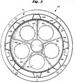
- the end cover assembly 30 receives a plurality (for example, five) fuel nozzle assemblies 32 (only one shown for purposes of convenience and clarity) arranged in a circular array about a longitudinal axis of the combustor (see Figure 5).
- a substantially cylindrical flow sleeve 34 which connects at its forward end to the outer wall 36 of the double walled transition duct 18.
- the flow sleeve 34 in connected at its rearward end by means of a radial flange 35 to the combustor casing 24 at a butt joint 37 where fore and aft sections of the combustor casing 24 art joined.
- combustion liner 38 which is connected at its forward end with the inner wall 40 of the transition duct 18.
- the rearward end of the combustion liner 38 is supported by a combustion liner cap assembly 42 which is, in turn, supported within the combustor casing by a plurality of struts 39 and associated mounting flange assembly 41 (best seen in Figure 5).
- the outer wall 36 of the transition duct 18, as well as that portion of flow sleeve 34 extending forward of the location where the combustion casing 24 is bolted to the turbine casing (by bolts 28) are formed with an array of apertures 44 over their respective peripheral surfaces to permit air to reverse flow from the compressor 12 through the apertures 44 into the annular space between the flow sleeve 34 and the liner 36 toward the upstream or rearward end of the combustor (as indicated by the flow arrows shown in Figure 1).
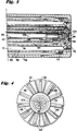
- the combustion liner cap assembly 42 supports a plurality of premix tubes 46, one for each fuel nozzle assembly 32. More specifically, each premix tube 46 is supported within the combustion liner cap assembly 42 at its forward and rearward ends by front and rear plates 47, 49, respectively, each provided with openings aligned with the open-ended premix tubes 46. This arrangement is best seen in Figure 5, with openings 43 shown in the front plate 47.
- the front plate 47 an impingement plate provided with an array of cooling apertures
- shield plates 45 may be shielded from the thermal radiation of the combustor flame by shield plates 45.
- the rear plate 49 mounts a plurality of rearwardly extending floating collars 48 (one for each premix tube, arranged in substantial alignment with the openings in the rear plate), each of which supports an air swirler 50 in surrounding relation to a radially outermost tube of the nozzle assembly 32.
- the arrangement is such that air flowing in the annular space between the liner 38 and flow sleeve 32 is forced to again reverse direction in the rearward end of the combustor (between the end cap assembly 30 and sleeve cap assembly 44) and to flow through the swirlers 50 and premix tubes 46 before entering the burning zone within the liner-38, downstream of the premix tubes 46.
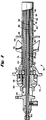
- each fuel nozzle assembly 32 includes a rearward supply section 52 with inlets for receiving liquid fuel, atomizing air, diffusion fuel and premix fuel, and with suitable connecting passages for supplying each of the above mentioned fluids to a respective passage in a forward delivery section 54 of the fuel nozzle assembly, as described below.
- the forward delivery section 54 of the fuel nozzle assembly is comprised of a series of concentric tubes.
- the two radially outermost concentric tubes 56, 58 provides a premix gas passage 60 which receives premix gas fuel from an inlet 62 connected to passage 60 by means of conduit 64.
- the premix gas passage 60 also communicates with a plurality (for example, eleven) radial fuel injectors 66, each of which in provided with a plurality of fuel injection ports or holes 68 for discharging gas fuel into a premix zone 69 located within the premix tube 46.
- the injected fuel mixes with air reverse flowed from the compressor 12, and swirled by means of the annular swirler 50 surrounding the fuel nozzle assembly upstream of the radial injectors 66.
- the premix passage 60 is sealed by an O-ring 72 at the forward or discharge end of the fuel nozzle assembly, so that premix fuel may exit only via the radial fuel injectors 66.
- the next adjacent passage 74 is formed between concentric tubes 58 and 76, and supplies diffusion gas to the burning zone 70 of the combustor via orifice 78 at the forwardmost end of the fuel nozzle assembly 32.
- the forwardmost or discharge end of the nozzle is located within the premix tube 36, but relatively close to the forward end thereof.
- the diffusion gas passage 74 receives diffusion gas from an inlet 80 via conduit 82.
- a third passage 84 is defined between concentric tubes 76 and 86 and supplies air to the burning zone 70 via orifice 88 where it then mixes with diffusion fuel exiting the orifice 78.
- the atomizing air is supplied to passage 84 from an inlet 90 via conduit 92.
- the fuel nozzle assembly 32 is also provided with a further passage 94 for (optionally) supplying water to the burning zone to effect NOx reductions in a manner understood by those skilled in the art.
- the water passage 94 in defined between tube 86 and adjacent concentric tube 96. Water exits the nozzle via an orifice 98, radially inward of the atomizing air orifice 88.
- Tube 96 the innermost of the series of concentric tubes forming the fuel injector nozzle, itself forms a central passage 100 for liquid fuel which enters the passage by means of inlet 102.
- the liquid fuel exits the nozzle by means of a discharge orifice 104 in the center of the nozzle.
- the liquid fuel capability is provided as a back-up system, and passage 100 is normally shut off while the turbine is in its normal gas fuel mode.
- the above described combustor is designed to act in a dual mode, single stage manner.
- diffusion gas fuel will be fed through inlet 80, conduit 82 and passage 74 for discharge via orifice 78 into the burning zone 70 where it mixes with atomizing air discharged from passage 84 via orifice 88. This mixture is ignited by spark plug 20 and burned in the zone 70 within the liner 38.
- premix fuel is supplied to passage 60 via inlet 62 and conduit 64 for discharge through orifices 68 in radial injectors 66.
- the diffusion fuel mixes with air entering the premix tube 46 by means of swirlers 50, the mixture igniting in burning zone 70 in liner 38 by the pre-existing flame from the diffusion mode of opera+ion.
- fuel to the diffusion passage 74 is shut down.
- combustion liner cooling may be achieved by axially spaced slot cooling rings, passive backside cooling, impingement cooling or any combination thereof. It will further be appreciated that combustion/cooling air may be supplied directly to the combustion liner cap assembly (exteriorly of the premix tubes) by moans of cooling holes formod in the outer sleeve of the assembly, which serve to direct air against the forward impingement plate and through the cooling apertures formed therein, to supplement the compressor air flowing through the dedicated premix tubes.
- the swirling flow field exiting the premix tubes coupled with the sudden expansion into the combustion liner, assist in establishing a stable burning zone within the combustor.
- a small percentage of fuel supplied to the radial premix gan injectors may be diverted to the downstream end of the nozzle to provide a diffusion flame ignition source (a sub-pilot).
- the primary purpose of this diffusion sub-pilot is to provide enhanced stability while in the premixed mode of operation.
Landscapes
- Engineering & Computer Science (AREA)
- Chemical & Material Sciences (AREA)
- Combustion & Propulsion (AREA)
- Mechanical Engineering (AREA)
- General Engineering & Computer Science (AREA)
- Spray-Type Burners (AREA)
- Fluidized-Bed Combustion And Resonant Combustion (AREA)
Applications Claiming Priority (2)
| Application Number | Priority Date | Filing Date | Title |
|---|---|---|---|
| US07/859,006 US5259184A (en) | 1992-03-30 | 1992-03-30 | Dry low NOx single stage dual mode combustor construction for a gas turbine |
| US859006 | 1992-03-30 |
Publications (2)
| Publication Number | Publication Date |
|---|---|
| EP0564184A1 true EP0564184A1 (fr) | 1993-10-06 |
| EP0564184B1 EP0564184B1 (fr) | 1996-12-11 |
Family
ID=25329745
Family Applications (1)
| Application Number | Title | Priority Date | Filing Date |
|---|---|---|---|
| EP93302351A Expired - Lifetime EP0564184B1 (fr) | 1992-03-30 | 1993-03-26 | Brûleur simple effet à deux modes d'opération |
Country Status (7)
| Country | Link |
|---|---|
| US (1) | US5259184A (fr) |
| EP (1) | EP0564184B1 (fr) |
| JP (1) | JP3330996B2 (fr) |
| KR (1) | KR100247097B1 (fr) |
| CN (1) | CN1106533C (fr) |
| DE (1) | DE69306447T2 (fr) |
| NO (1) | NO300289B1 (fr) |
Cited By (13)
| Publication number | Priority date | Publication date | Assignee | Title |
|---|---|---|---|---|
| EP0594127A1 (fr) * | 1992-10-19 | 1994-04-27 | Mitsubishi Jukogyo Kabushiki Kaisha | Chambre de combustion pour turbine à gaz |
| EP0730121A3 (fr) * | 1995-03-01 | 1998-03-11 | Abb Research Ltd. | Brûleur à prémélange |
| EP0823591A3 (fr) * | 1996-08-06 | 1998-09-30 | General Electric Company | Dispositif et procédé d'injection de jets isolés d'un combustible liquide pulvérisé par l'air |
| US6594999B2 (en) | 2000-07-21 | 2003-07-22 | Mitsubishi Heavy Industries, Ltd. | Combustor, a gas turbine, and a jet engine |
| US7284378B2 (en) | 2004-06-04 | 2007-10-23 | General Electric Company | Methods and apparatus for low emission gas turbine energy generation |
| WO2008033542A3 (fr) * | 2006-09-14 | 2008-05-08 | Solar Turbines Inc | Injecteur de carburant de turbine à gaz avec un ensemble pilote amovible |
| WO2008057685A3 (fr) * | 2006-10-06 | 2008-09-12 | Gen Electric | Buse de brûleur pour un système de combustion adapté à divers combustibles |
| US7707833B1 (en) | 2009-02-04 | 2010-05-04 | Gas Turbine Efficiency Sweden Ab | Combustor nozzle |
| US8286433B2 (en) | 2007-10-26 | 2012-10-16 | Solar Turbines Inc. | Gas turbine fuel injector with removable pilot liquid tube |
| WO2011048123A3 (fr) * | 2009-10-20 | 2012-12-20 | Siemens Aktiengesellschaft | Système de combustion multicarburant |
| US10859264B2 (en) | 2017-03-07 | 2020-12-08 | 8 Rivers Capital, Llc | System and method for combustion of non-gaseous fuels and derivatives thereof |
| US11199327B2 (en) | 2017-03-07 | 2021-12-14 | 8 Rivers Capital, Llc | Systems and methods for operation of a flexible fuel combustor |
| US11572828B2 (en) | 2018-07-23 | 2023-02-07 | 8 Rivers Capital, Llc | Systems and methods for power generation with flameless combustion |
Families Citing this family (130)
| Publication number | Priority date | Publication date | Assignee | Title |
|---|---|---|---|---|
| IT1263683B (it) * | 1992-08-21 | 1996-08-27 | Westinghouse Electric Corp | Complesso di ugello per combustibile per una turbina a gas |
| US5487275A (en) * | 1992-12-11 | 1996-01-30 | General Electric Co. | Tertiary fuel injection system for use in a dry low NOx combustion system |
| US5408825A (en) * | 1993-12-03 | 1995-04-25 | Westinghouse Electric Corporation | Dual fuel gas turbine combustor |
| US5426933A (en) * | 1994-01-11 | 1995-06-27 | Solar Turbines Incorporated | Dual feed injection nozzle with water injection |
| US5408830A (en) | 1994-02-10 | 1995-04-25 | General Electric Company | Multi-stage fuel nozzle for reducing combustion instabilities in low NOX gas turbines |
| JP2950720B2 (ja) * | 1994-02-24 | 1999-09-20 | 株式会社東芝 | ガスタービン燃焼装置およびその燃焼制御方法 |
| US5461865A (en) * | 1994-02-24 | 1995-10-31 | United Technologies Corporation | Tangential entry fuel nozzle |
| DE69515931T2 (de) * | 1994-06-10 | 2000-11-02 | General Electric Co., Schenectady | Regelung einer Gasturbinenbrennkammer |
| US5491970A (en) * | 1994-06-10 | 1996-02-20 | General Electric Co. | Method for staging fuel in a turbine between diffusion and premixed operations |
| US5415000A (en) * | 1994-06-13 | 1995-05-16 | Westinghouse Electric Corporation | Low NOx combustor retro-fit system for gas turbines |
| US5471840A (en) * | 1994-07-05 | 1995-12-05 | General Electric Company | Bluffbody flameholders for low emission gas turbine combustors |
| JP3116081B2 (ja) * | 1994-07-29 | 2000-12-11 | 科学技術庁航空宇宙技術研究所長 | 空気配分制御ガスタービン燃焼器 |
| US5943866A (en) * | 1994-10-03 | 1999-08-31 | General Electric Company | Dynamically uncoupled low NOx combustor having multiple premixers with axial staging |
| EP0747635B1 (fr) * | 1995-06-05 | 2003-01-15 | Rolls-Royce Corporation | Brûleur à prémélange pauvre avec faible production de NOx pour turbines à gaz industrielles |
| US5813232A (en) * | 1995-06-05 | 1998-09-29 | Allison Engine Company, Inc. | Dry low emission combustor for gas turbine engines |
| US5722230A (en) * | 1995-08-08 | 1998-03-03 | General Electric Co. | Center burner in a multi-burner combustor |
| JP3939756B2 (ja) * | 1995-09-22 | 2007-07-04 | シーメンス アクチエンゲゼルシヤフト | 特にガスタービン用のバーナ |
| US5647215A (en) * | 1995-11-07 | 1997-07-15 | Westinghouse Electric Corporation | Gas turbine combustor with turbulence enhanced mixing fuel injectors |
| US5685139A (en) * | 1996-03-29 | 1997-11-11 | General Electric Company | Diffusion-premix nozzle for a gas turbine combustor and related method |
| US6047550A (en) | 1996-05-02 | 2000-04-11 | General Electric Co. | Premixing dry low NOx emissions combustor with lean direct injection of gas fuel |
| WO1998025084A1 (fr) * | 1996-12-04 | 1998-06-11 | Siemens Westinghouse Power Corporation | VEILLEUSE DE DIFFUSION A PREMELANGE POUR BRULEUR A FAIBLE DEGAGEMENT DE NOx |
| US5873237A (en) * | 1997-01-24 | 1999-02-23 | Westinghouse Electric Corporation | Atomizing dual fuel nozzle for a combustion turbine |
| KR100550689B1 (ko) | 1998-02-10 | 2006-02-08 | 제너럴 일렉트릭 캄파니 | 가스 터빈의 연소 시스템용 버너 및 연료와 공기의 예비혼합 방법 |
| US6598383B1 (en) * | 1999-12-08 | 2003-07-29 | General Electric Co. | Fuel system configuration and method for staging fuel for gas turbines utilizing both gaseous and liquid fuels |
| US6983605B1 (en) * | 2000-04-07 | 2006-01-10 | General Electric Company | Methods and apparatus for reducing gas turbine engine emissions |
| US6363724B1 (en) | 2000-08-31 | 2002-04-02 | General Electric Company | Gas only nozzle fuel tip |
| JP3846169B2 (ja) * | 2000-09-14 | 2006-11-15 | 株式会社日立製作所 | ガスタービンの補修方法 |
| JP4610796B2 (ja) * | 2001-06-13 | 2011-01-12 | 三菱重工業株式会社 | ガスタービン燃焼器 |
| JP3986348B2 (ja) * | 2001-06-29 | 2007-10-03 | 三菱重工業株式会社 | ガスタービン燃焼器の燃料供給ノズルおよびガスタービン燃焼器並びにガスタービン |
| JP2003065537A (ja) * | 2001-08-24 | 2003-03-05 | Mitsubishi Heavy Ind Ltd | ガスタービン燃焼器 |
| EP1456583B1 (fr) * | 2001-12-20 | 2007-10-10 | Alstom Technology Ltd | Procédé d'injection d'un mélange air/carburant dans une chambre de combustion |
| US6715295B2 (en) | 2002-05-22 | 2004-04-06 | Siemens Westinghouse Power Corporation | Gas turbine pilot burner water injection and method of operation |
| US6672073B2 (en) * | 2002-05-22 | 2004-01-06 | Siemens Westinghouse Power Corporation | System and method for supporting fuel nozzles in a gas turbine combustor utilizing a support plate |
| US6708496B2 (en) | 2002-05-22 | 2004-03-23 | Siemens Westinghouse Power Corporation | Humidity compensation for combustion control in a gas turbine engine |
| US6735949B1 (en) * | 2002-06-11 | 2004-05-18 | General Electric Company | Gas turbine engine combustor can with trapped vortex cavity |
| US6675581B1 (en) * | 2002-07-15 | 2004-01-13 | Power Systems Mfg, Llc | Fully premixed secondary fuel nozzle |
| US6691516B2 (en) * | 2002-07-15 | 2004-02-17 | Power Systems Mfg, Llc | Fully premixed secondary fuel nozzle with improved stability |
| US7165405B2 (en) * | 2002-07-15 | 2007-01-23 | Power Systems Mfg. Llc | Fully premixed secondary fuel nozzle with dual fuel capability |
| US6698207B1 (en) | 2002-09-11 | 2004-03-02 | Siemens Westinghouse Power Corporation | Flame-holding, single-mode nozzle assembly with tip cooling |
| US6786046B2 (en) | 2002-09-11 | 2004-09-07 | Siemens Westinghouse Power Corporation | Dual-mode nozzle assembly with passive tip cooling |
| US6775987B2 (en) | 2002-09-12 | 2004-08-17 | The Boeing Company | Low-emission, staged-combustion power generation |
| US6755359B2 (en) | 2002-09-12 | 2004-06-29 | The Boeing Company | Fluid mixing injector and method |
| US6802178B2 (en) * | 2002-09-12 | 2004-10-12 | The Boeing Company | Fluid injection and injection method |
| EP1508747A1 (fr) * | 2003-08-18 | 2005-02-23 | Siemens Aktiengesellschaft | Diffuseur de turbine à gaz et turbine à gaz pour la production d'énergie |
| US20060283181A1 (en) * | 2005-06-15 | 2006-12-21 | Arvin Technologies, Inc. | Swirl-stabilized burner for thermal management of exhaust system and associated method |
| US7137258B2 (en) * | 2004-06-03 | 2006-11-21 | General Electric Company | Swirler configurations for combustor nozzles and related method |
| US6993916B2 (en) * | 2004-06-08 | 2006-02-07 | General Electric Company | Burner tube and method for mixing air and gas in a gas turbine engine |
| US7082765B2 (en) * | 2004-09-01 | 2006-08-01 | General Electric Company | Methods and apparatus for reducing gas turbine engine emissions |
| US7185495B2 (en) | 2004-09-07 | 2007-03-06 | General Electric Company | System and method for improving thermal efficiency of dry low emissions combustor assemblies |
| US7546735B2 (en) * | 2004-10-14 | 2009-06-16 | General Electric Company | Low-cost dual-fuel combustor and related method |
| US20070119179A1 (en) * | 2005-11-30 | 2007-05-31 | Haynes Joel M | Opposed flow combustor |
| US7805946B2 (en) * | 2005-12-08 | 2010-10-05 | Siemens Energy, Inc. | Combustor flow sleeve attachment system |
| US7677472B2 (en) * | 2005-12-08 | 2010-03-16 | General Electric Company | Drilled and integrated secondary fuel nozzle and manufacturing method |
| US20070151251A1 (en) * | 2006-01-03 | 2007-07-05 | Haynes Joel M | Counterflow injection mechanism having coaxial fuel-air passages |
| US8387390B2 (en) * | 2006-01-03 | 2013-03-05 | General Electric Company | Gas turbine combustor having counterflow injection mechanism |
| US20080078182A1 (en) * | 2006-09-29 | 2008-04-03 | Andrei Tristan Evulet | Premixing device, gas turbines comprising the premixing device, and methods of use |
| US8448441B2 (en) * | 2007-07-26 | 2013-05-28 | General Electric Company | Fuel nozzle assembly for a gas turbine engine |
| US7966820B2 (en) * | 2007-08-15 | 2011-06-28 | General Electric Company | Method and apparatus for combusting fuel within a gas turbine engine |
| US8171716B2 (en) * | 2007-08-28 | 2012-05-08 | General Electric Company | System and method for fuel and air mixing in a gas turbine |
| US20090056336A1 (en) | 2007-08-28 | 2009-03-05 | General Electric Company | Gas turbine premixer with radially staged flow passages and method for mixing air and gas in a gas turbine |
| US8136359B2 (en) * | 2007-12-10 | 2012-03-20 | Power Systems Mfg., Llc | Gas turbine fuel nozzle having improved thermal capability |
| US7908863B2 (en) * | 2008-02-12 | 2011-03-22 | General Electric Company | Fuel nozzle for a gas turbine engine and method for fabricating the same |
| US8631656B2 (en) * | 2008-03-31 | 2014-01-21 | General Electric Company | Gas turbine engine combustor circumferential acoustic reduction using flame temperature nonuniformities |
| US20090249789A1 (en) | 2008-04-08 | 2009-10-08 | Baifang Zuo | Burner tube premixer and method for mixing air and gas in a gas turbine engine |
| US8147121B2 (en) * | 2008-07-09 | 2012-04-03 | General Electric Company | Pre-mixing apparatus for a turbine engine |
| US20100024425A1 (en) * | 2008-07-31 | 2010-02-04 | General Electric Company | Turbine engine fuel nozzle |
| US8112999B2 (en) * | 2008-08-05 | 2012-02-14 | General Electric Company | Turbomachine injection nozzle including a coolant delivery system |
| US8220272B2 (en) * | 2008-12-04 | 2012-07-17 | General Electric Company | Combustor housing for combustion of low-BTU fuel gases and methods of making and using the same |
| US8297059B2 (en) * | 2009-01-22 | 2012-10-30 | General Electric Company | Nozzle for a turbomachine |
| US9140454B2 (en) * | 2009-01-23 | 2015-09-22 | General Electric Company | Bundled multi-tube nozzle for a turbomachine |
| US8539773B2 (en) * | 2009-02-04 | 2013-09-24 | General Electric Company | Premixed direct injection nozzle for highly reactive fuels |
| US8365535B2 (en) * | 2009-02-09 | 2013-02-05 | General Electric Company | Fuel nozzle with multiple fuel passages within a radial swirler |
| US8347631B2 (en) * | 2009-03-03 | 2013-01-08 | General Electric Company | Fuel nozzle liquid cartridge including a fuel insert |
| US8689559B2 (en) | 2009-03-30 | 2014-04-08 | General Electric Company | Secondary combustion system for reducing the level of emissions generated by a turbomachine |
| US8256226B2 (en) | 2009-04-23 | 2012-09-04 | General Electric Company | Radial lean direct injection burner |
| US20100281876A1 (en) * | 2009-05-05 | 2010-11-11 | Abdul Rafey Khan | Fuel blanketing by inert gas or less reactive fuel layer to prevent flame holding in premixers |
| US8607568B2 (en) * | 2009-05-14 | 2013-12-17 | General Electric Company | Dry low NOx combustion system with pre-mixed direct-injection secondary fuel nozzle |
| US20100287938A1 (en) * | 2009-05-14 | 2010-11-18 | General Electric Company | Cross flow vane |
| US8079218B2 (en) * | 2009-05-21 | 2011-12-20 | General Electric Company | Method and apparatus for combustor nozzle with flameholding protection |
| US20100319353A1 (en) * | 2009-06-18 | 2010-12-23 | John Charles Intile | Multiple Fuel Circuits for Syngas/NG DLN in a Premixed Nozzle |
| US8789372B2 (en) * | 2009-07-08 | 2014-07-29 | General Electric Company | Injector with integrated resonator |
| US8468831B2 (en) * | 2009-07-13 | 2013-06-25 | General Electric Company | Lean direct injection for premixed pilot application |
| US20110023494A1 (en) | 2009-07-28 | 2011-02-03 | General Electric Company | Gas turbine burner |
| US8381526B2 (en) * | 2010-02-15 | 2013-02-26 | General Electric Company | Systems and methods of providing high pressure air to a head end of a combustor |
| US20110209481A1 (en) * | 2010-02-26 | 2011-09-01 | General Electric Company | Turbine Combustor End Cover |
| US8418468B2 (en) | 2010-04-06 | 2013-04-16 | General Electric Company | Segmented annular ring-manifold quaternary fuel distributor |
| US8438852B2 (en) * | 2010-04-06 | 2013-05-14 | General Electric Company | Annular ring-manifold quaternary fuel distributor |
| US8919673B2 (en) * | 2010-04-14 | 2014-12-30 | General Electric Company | Apparatus and method for a fuel nozzle |
| US8752386B2 (en) * | 2010-05-25 | 2014-06-17 | Siemens Energy, Inc. | Air/fuel supply system for use in a gas turbine engine |
| US8572979B2 (en) | 2010-06-24 | 2013-11-05 | United Technologies Corporation | Gas turbine combustor liner cap assembly |
| US8959921B2 (en) | 2010-07-13 | 2015-02-24 | General Electric Company | Flame tolerant secondary fuel nozzle |
| US9557050B2 (en) | 2010-07-30 | 2017-01-31 | General Electric Company | Fuel nozzle and assembly and gas turbine comprising the same |
| US8925324B2 (en) * | 2010-10-05 | 2015-01-06 | General Electric Company | Turbomachine including a mixing tube element having a vortex generator |
| US8820086B2 (en) * | 2011-01-18 | 2014-09-02 | General Electric Company | Gas turbine combustor endcover assembly with integrated flow restrictor and manifold seal |
| US20120180486A1 (en) * | 2011-01-18 | 2012-07-19 | General Electric Company | Gas turbine fuel system for low dynamics |
| US8733106B2 (en) * | 2011-05-03 | 2014-05-27 | General Electric Company | Fuel injector and support plate |
| US8919132B2 (en) | 2011-05-18 | 2014-12-30 | Solar Turbines Inc. | Method of operating a gas turbine engine |
| US8893500B2 (en) | 2011-05-18 | 2014-11-25 | Solar Turbines Inc. | Lean direct fuel injector |
| US9388988B2 (en) * | 2011-05-20 | 2016-07-12 | Siemens Energy, Inc. | Gas turbine combustion cap assembly |
| US20120297784A1 (en) * | 2011-05-24 | 2012-11-29 | General Electric Company | System and method for flow control in gas turbine engine |
| US8601820B2 (en) | 2011-06-06 | 2013-12-10 | General Electric Company | Integrated late lean injection on a combustion liner and late lean injection sleeve assembly |
| US20130025253A1 (en) | 2011-07-27 | 2013-01-31 | Rajani Kumar Akula | Reduction of co and o2 emissions in oxyfuel hydrocarbon combustion systems using oh radical formation with hydrogen fuel staging and diluent addition |
| US8919137B2 (en) | 2011-08-05 | 2014-12-30 | General Electric Company | Assemblies and apparatus related to integrating late lean injection into combustion turbine engines |
| US9010120B2 (en) | 2011-08-05 | 2015-04-21 | General Electric Company | Assemblies and apparatus related to integrating late lean injection into combustion turbine engines |
| US20130040254A1 (en) * | 2011-08-08 | 2013-02-14 | General Electric Company | System and method for monitoring a combustor |
| CN103134078B (zh) | 2011-11-25 | 2015-03-25 | 中国科学院工程热物理研究所 | 一种阵列驻涡燃料-空气预混器 |
| US9182124B2 (en) | 2011-12-15 | 2015-11-10 | Solar Turbines Incorporated | Gas turbine and fuel injector for the same |
| US9719685B2 (en) * | 2011-12-20 | 2017-08-01 | General Electric Company | System and method for flame stabilization |
| US9140455B2 (en) | 2012-01-04 | 2015-09-22 | General Electric Company | Flowsleeve of a turbomachine component |
| US9366440B2 (en) * | 2012-01-04 | 2016-06-14 | General Electric Company | Fuel nozzles with mixing tubes surrounding a liquid fuel cartridge for injecting fuel in a gas turbine combustor |
| US9217570B2 (en) * | 2012-01-20 | 2015-12-22 | General Electric Company | Axial flow fuel nozzle with a stepped center body |
| WO2013128572A1 (fr) * | 2012-02-28 | 2013-09-06 | 三菱重工業株式会社 | Brûleur, et turbine à gaz |
| US9267690B2 (en) | 2012-05-29 | 2016-02-23 | General Electric Company | Turbomachine combustor nozzle including a monolithic nozzle component and method of forming the same |
| US9395084B2 (en) * | 2012-06-06 | 2016-07-19 | General Electric Company | Fuel pre-mixer with planar and swirler vanes |
| US10100741B2 (en) * | 2012-11-02 | 2018-10-16 | General Electric Company | System and method for diffusion combustion with oxidant-diluent mixing in a stoichiometric exhaust gas recirculation gas turbine system |
| JP5980186B2 (ja) * | 2013-09-26 | 2016-08-31 | 三菱重工業株式会社 | バーナー、および、石炭改質プラント |
| JP6015618B2 (ja) * | 2013-10-04 | 2016-10-26 | トヨタ自動車株式会社 | 車両 |
| US20160348911A1 (en) * | 2013-12-12 | 2016-12-01 | Siemens Energy, Inc. | W501 d5/d5a df42 combustion system |
| EP2905535A1 (fr) | 2014-02-06 | 2015-08-12 | Siemens Aktiengesellschaft | Chambre à combustion |
| JP6177187B2 (ja) * | 2014-04-30 | 2017-08-09 | 三菱日立パワーシステムズ株式会社 | ガスタービン燃焼器、ガスタービン、制御装置及び制御方法 |
| CN104132346A (zh) * | 2014-07-01 | 2014-11-05 | 天津大学 | 一种具有回热功能的微燃烧热光伏发电装置 |
| US10060629B2 (en) * | 2015-02-20 | 2018-08-28 | United Technologies Corporation | Angled radial fuel/air delivery system for combustor |
| RU2015156419A (ru) | 2015-12-28 | 2017-07-04 | Дженерал Электрик Компани | Узел топливной форсунки, выполненный со стабилизатором пламени предварительно перемешанной смеси |
| US10274201B2 (en) | 2016-01-05 | 2019-04-30 | Solar Turbines Incorporated | Fuel injector with dual main fuel injection |
| US20170370589A1 (en) | 2016-06-22 | 2017-12-28 | General Electric Company | Multi-tube late lean injector |
| KR102046457B1 (ko) * | 2017-11-09 | 2019-11-19 | 두산중공업 주식회사 | 연소기 및 이를 포함하는 가스 터빈 |
| KR102119879B1 (ko) * | 2018-03-07 | 2020-06-08 | 두산중공업 주식회사 | 파일럿 연료 분사 장치, 이를 구비한 연료 노즐 및 가스 터빈 |
| US11156360B2 (en) * | 2019-02-18 | 2021-10-26 | General Electric Company | Fuel nozzle assembly |
| JP7335038B2 (ja) | 2019-11-08 | 2023-08-29 | 東芝エネルギーシステムズ株式会社 | ガスタービン燃焼器構造体 |
| US20240418127A1 (en) * | 2023-06-16 | 2024-12-19 | Raytheon Technologies Corporation | Gaseous fuel and liquid water injection for turbine engine |
Citations (6)
| Publication number | Priority date | Publication date | Assignee | Title |
|---|---|---|---|---|
| EP0108361A1 (fr) * | 1982-11-08 | 1984-05-16 | Kraftwerk Union Aktiengesellschaft | Brûleur de prémélange avec brûleur à diffusion intégré |
| EP0204553A1 (fr) * | 1985-06-07 | 1986-12-10 | Ruston Gas Turbines Limited | Chaudière de combustion pour une turbine à gaz |
| DE3835415A1 (de) * | 1987-10-23 | 1989-05-03 | Gen Electric | Brennstoffinjektor fuer eine brennkammer eines gasturbinentriebwerks |
| DE3913124A1 (de) * | 1986-02-24 | 1989-12-14 | Asea Brown Boveri | Brennstoffduese |
| US4982570A (en) * | 1986-11-25 | 1991-01-08 | General Electric Company | Premixed pilot nozzle for dry low Nox combustor |
| EP0488556A1 (fr) * | 1990-11-27 | 1992-06-03 | General Electric Company | Injecteur secondaire de carburant à prémélange avec dispositif de tourbillonnement incorporé |
Family Cites Families (43)
| Publication number | Priority date | Publication date | Assignee | Title |
|---|---|---|---|---|
| DE1074920B (de) * | 1955-07-07 | 1960-02-04 | Ing habil Fritz A F Schmidt Murnau Dr (Obb) | Verfahren und \ orrichtung zur Regelung von Gas turbmenbrennkammern mit unterteilter Verbrennung und mehreren Druckstufen |
| US2955420A (en) * | 1955-09-12 | 1960-10-11 | Phillips Petroleum Co | Jet engine operation |
| US2999359A (en) * | 1956-04-25 | 1961-09-12 | Rolls Royce | Combustion equipment of gas-turbine engines |
| US2993338A (en) * | 1958-04-09 | 1961-07-25 | Gen Motors Corp | Fuel spray bar assembly |
| US3164200A (en) * | 1962-06-27 | 1965-01-05 | Zink Co John | Multiple fuel burner |
| US3149463A (en) * | 1963-01-04 | 1964-09-22 | Bristol Siddeley Engines Ltd | Variable spread fuel dispersal system |
| US3792582A (en) * | 1970-10-26 | 1974-02-19 | United Aircraft Corp | Combustion chamber for dissimilar fluids in swirling flow relationship |
| US3912164A (en) * | 1971-01-11 | 1975-10-14 | Parker Hannifin Corp | Method of liquid fuel injection, and to air blast atomizers |
| US3899881A (en) * | 1974-02-04 | 1975-08-19 | Gen Motors Corp | Combustion apparatus with secondary air to vaporization chamber and concurrent variance of secondary air and dilution air in a reverse sense |
| US4173118A (en) * | 1974-08-27 | 1979-11-06 | Mitsubishi Jukogyo Kabushiki Kaisha | Fuel combustion apparatus employing staged combustion |
| US3958416A (en) * | 1974-12-12 | 1976-05-25 | General Motors Corporation | Combustion apparatus |
| US3973395A (en) * | 1974-12-18 | 1976-08-10 | United Technologies Corporation | Low emission combustion chamber |
| US3946553A (en) * | 1975-03-10 | 1976-03-30 | United Technologies Corporation | Two-stage premixed combustor |
| GB1575410A (en) * | 1976-09-04 | 1980-09-24 | Rolls Royce | Combustion apparatus for use in gas turbine engines |
| US4112676A (en) * | 1977-04-05 | 1978-09-12 | Westinghouse Electric Corp. | Hybrid combustor with staged injection of pre-mixed fuel |
| US4262482A (en) * | 1977-11-17 | 1981-04-21 | Roffe Gerald A | Apparatus for the premixed gas phase combustion of liquid fuels |
| US4498288A (en) * | 1978-10-13 | 1985-02-12 | General Electric Company | Fuel injection staged sectoral combustor for burning low-BTU fuel gas |
| US4420929A (en) * | 1979-01-12 | 1983-12-20 | General Electric Company | Dual stage-dual mode low emission gas turbine combustion system |
| GB2050592B (en) * | 1979-06-06 | 1983-03-16 | Rolls Royce | Gas turbine |
| US4292801A (en) * | 1979-07-11 | 1981-10-06 | General Electric Company | Dual stage-dual mode low nox combustor |
| US4425755A (en) * | 1980-09-16 | 1984-01-17 | Rolls-Royce Limited | Gas turbine dual fuel burners |
| US4389848A (en) * | 1981-01-12 | 1983-06-28 | United Technologies Corporation | Burner construction for gas turbines |
| US4698963A (en) * | 1981-04-22 | 1987-10-13 | The United States Of America As Represented By The Department Of Energy | Low NOx combustor |
| JPS57207711A (en) * | 1981-06-15 | 1982-12-20 | Hitachi Ltd | Premixture and revolving burner |
| US4483137A (en) * | 1981-07-30 | 1984-11-20 | Solar Turbines, Incorporated | Gas turbine engine construction and operation |
| US4787208A (en) * | 1982-03-08 | 1988-11-29 | Westinghouse Electric Corp. | Low-nox, rich-lean combustor |
| US4600151A (en) * | 1982-11-23 | 1986-07-15 | Ex-Cell-O Corporation | Fuel injector assembly with water or auxiliary fuel capability |
| FR2572463B1 (fr) * | 1984-10-30 | 1989-01-20 | Snecma | Systeme d'injection a geometrie variable. |
| JPH0621572B2 (ja) * | 1984-12-14 | 1994-03-23 | 株式会社日立製作所 | ガスタービンプラントの起動方法及びガスタービンプラント |
| DE3663189D1 (en) * | 1985-03-04 | 1989-06-08 | Siemens Ag | Burner disposition for combustion installations, especially for combustion chambers of gas turbine installations, and method for its operation |
| JPS61241425A (ja) * | 1985-04-17 | 1986-10-27 | Hitachi Ltd | ガスタ−ビンの燃料ガス制御方法及び制御装置 |
| GB2175993B (en) * | 1985-06-07 | 1988-12-21 | Rolls Royce | Improvements in or relating to dual fuel injectors |
| DE3766807D1 (de) * | 1986-11-25 | 1991-01-31 | Gen Electric | Kombinierter diffusions- und vormischpilotbrenner. |
| US4984429A (en) * | 1986-11-25 | 1991-01-15 | General Electric Company | Impingement cooled liner for dry low NOx venturi combustor |
| CH672366A5 (fr) * | 1986-12-09 | 1989-11-15 | Bbc Brown Boveri & Cie | |
| CH672541A5 (fr) * | 1986-12-11 | 1989-11-30 | Bbc Brown Boveri & Cie | |
| EP0276696B1 (fr) * | 1987-01-26 | 1990-09-12 | Siemens Aktiengesellschaft | Brûleur hybride pour fonctionnement en prémélange au gaz et/ou au mazout, notamment pour turbines à gaz |
| JP2644745B2 (ja) * | 1987-03-06 | 1997-08-25 | 株式会社日立製作所 | ガスタービン用燃焼器 |
| SE459364B (sv) * | 1987-11-13 | 1989-06-26 | Odd Olsson | Foerbraenningsanordning |
| US4901524A (en) * | 1987-11-20 | 1990-02-20 | Sundstrand Corporation | Staged, coaxial, multiple point fuel injection in a hot gas generator |
| US4974415A (en) * | 1987-11-20 | 1990-12-04 | Sundstrand Corporation | Staged, coaxial multiple point fuel injection in a hot gas generator |
| US4996837A (en) * | 1987-12-28 | 1991-03-05 | Sundstrand Corporation | Gas turbine with forced vortex fuel injection |
| JPH0684817B2 (ja) * | 1988-08-08 | 1994-10-26 | 株式会社日立製作所 | ガスタービン燃焼器及びその運転方法 |
-
1992
- 1992-03-30 US US07/859,006 patent/US5259184A/en not_active Expired - Lifetime
-
1993
- 1993-02-26 KR KR1019930002737A patent/KR100247097B1/ko not_active Expired - Lifetime
- 1993-03-26 DE DE69306447T patent/DE69306447T2/de not_active Expired - Lifetime
- 1993-03-26 EP EP93302351A patent/EP0564184B1/fr not_active Expired - Lifetime
- 1993-03-26 JP JP06723293A patent/JP3330996B2/ja not_active Expired - Lifetime
- 1993-03-27 CN CN93103559A patent/CN1106533C/zh not_active Expired - Lifetime
- 1993-03-29 NO NO931170A patent/NO300289B1/no not_active IP Right Cessation
Patent Citations (6)
| Publication number | Priority date | Publication date | Assignee | Title |
|---|---|---|---|---|
| EP0108361A1 (fr) * | 1982-11-08 | 1984-05-16 | Kraftwerk Union Aktiengesellschaft | Brûleur de prémélange avec brûleur à diffusion intégré |
| EP0204553A1 (fr) * | 1985-06-07 | 1986-12-10 | Ruston Gas Turbines Limited | Chaudière de combustion pour une turbine à gaz |
| DE3913124A1 (de) * | 1986-02-24 | 1989-12-14 | Asea Brown Boveri | Brennstoffduese |
| US4982570A (en) * | 1986-11-25 | 1991-01-08 | General Electric Company | Premixed pilot nozzle for dry low Nox combustor |
| DE3835415A1 (de) * | 1987-10-23 | 1989-05-03 | Gen Electric | Brennstoffinjektor fuer eine brennkammer eines gasturbinentriebwerks |
| EP0488556A1 (fr) * | 1990-11-27 | 1992-06-03 | General Electric Company | Injecteur secondaire de carburant à prémélange avec dispositif de tourbillonnement incorporé |
Cited By (22)
| Publication number | Priority date | Publication date | Assignee | Title |
|---|---|---|---|---|
| EP0594127A1 (fr) * | 1992-10-19 | 1994-04-27 | Mitsubishi Jukogyo Kabushiki Kaisha | Chambre de combustion pour turbine à gaz |
| US5410884A (en) * | 1992-10-19 | 1995-05-02 | Mitsubishi Jukogyo Kabushiki Kaisha | Combustor for gas turbines with diverging pilot nozzle cone |
| EP0730121A3 (fr) * | 1995-03-01 | 1998-03-11 | Abb Research Ltd. | Brûleur à prémélange |
| EP0823591A3 (fr) * | 1996-08-06 | 1998-09-30 | General Electric Company | Dispositif et procédé d'injection de jets isolés d'un combustible liquide pulvérisé par l'air |
| US6594999B2 (en) | 2000-07-21 | 2003-07-22 | Mitsubishi Heavy Industries, Ltd. | Combustor, a gas turbine, and a jet engine |
| US7284378B2 (en) | 2004-06-04 | 2007-10-23 | General Electric Company | Methods and apparatus for low emission gas turbine energy generation |
| CN101529163B (zh) * | 2006-09-14 | 2012-01-04 | 索拉透平公司 | 带有可移除的引导组件的燃气轮机燃料喷射器 |
| GB2455428B (en) * | 2006-09-14 | 2010-11-10 | Solar Turbines Inc | Gas turbine fuel injector with a removable pilot assembly |
| WO2008033542A3 (fr) * | 2006-09-14 | 2008-05-08 | Solar Turbines Inc | Injecteur de carburant de turbine à gaz avec un ensemble pilote amovible |
| US8166763B2 (en) | 2006-09-14 | 2012-05-01 | Solar Turbines Inc. | Gas turbine fuel injector with a removable pilot assembly |
| WO2008057685A3 (fr) * | 2006-10-06 | 2008-09-12 | Gen Electric | Buse de brûleur pour un système de combustion adapté à divers combustibles |
| US8286433B2 (en) | 2007-10-26 | 2012-10-16 | Solar Turbines Inc. | Gas turbine fuel injector with removable pilot liquid tube |
| US7707833B1 (en) | 2009-02-04 | 2010-05-04 | Gas Turbine Efficiency Sweden Ab | Combustor nozzle |
| WO2011048123A3 (fr) * | 2009-10-20 | 2012-12-20 | Siemens Aktiengesellschaft | Système de combustion multicarburant |
| CN102844622A (zh) * | 2009-10-20 | 2012-12-26 | 西门子公司 | 一种多燃料燃烧系统 |
| CN102844622B (zh) * | 2009-10-20 | 2015-08-26 | 西门子公司 | 一种多燃料燃烧系统 |
| US10859264B2 (en) | 2017-03-07 | 2020-12-08 | 8 Rivers Capital, Llc | System and method for combustion of non-gaseous fuels and derivatives thereof |
| US11199327B2 (en) | 2017-03-07 | 2021-12-14 | 8 Rivers Capital, Llc | Systems and methods for operation of a flexible fuel combustor |
| US11435077B2 (en) | 2017-03-07 | 2022-09-06 | 8 Rivers Capital, Llc | System and method for combustion of non-gaseous fuels and derivatives thereof |
| US11828468B2 (en) | 2017-03-07 | 2023-11-28 | 8 Rivers Capital, Llc | Systems and methods for operation of a flexible fuel combustor |
| US12259136B2 (en) | 2017-03-07 | 2025-03-25 | 8 Rivers Capital, Llc | Systems and methods for operation of a flexible fuel combustor |
| US11572828B2 (en) | 2018-07-23 | 2023-02-07 | 8 Rivers Capital, Llc | Systems and methods for power generation with flameless combustion |
Also Published As
| Publication number | Publication date |
|---|---|
| JP3330996B2 (ja) | 2002-10-07 |
| CN1078789A (zh) | 1993-11-24 |
| DE69306447T2 (de) | 1997-06-05 |
| NO931170L (no) | 1993-10-01 |
| NO300289B1 (no) | 1997-05-05 |
| NO931170D0 (no) | 1993-03-29 |
| JPH0618037A (ja) | 1994-01-25 |
| KR930020090A (ko) | 1993-10-19 |
| EP0564184B1 (fr) | 1996-12-11 |
| DE69306447D1 (de) | 1997-01-23 |
| CN1106533C (zh) | 2003-04-23 |
| US5259184A (en) | 1993-11-09 |
| KR100247097B1 (ko) | 2000-04-01 |
Similar Documents
| Publication | Publication Date | Title |
|---|---|---|
| EP0564184B1 (fr) | Brûleur simple effet à deux modes d'opération | |
| EP0667492B1 (fr) | Injecteur de carburant | |
| US5685139A (en) | Diffusion-premix nozzle for a gas turbine combustor and related method | |
| US7185494B2 (en) | Reduced center burner in multi-burner combustor and method for operating the combustor | |
| EP0686812B1 (fr) | Méthode de régulation pour une chambre de combustion d'une turbine à gaz | |
| CA2103433C (fr) | Systeme tertiaire d'injection de carburant pour utilisation dans un systeme de combustion a faible degagement d'oxydes d'azote | |
| US5729968A (en) | Center burner in a multi-burner combustor | |
| EP0691511B1 (fr) | Méthode de régulation pour une chambre de combustion d'une turbine à gaz | |
| EP0488556B1 (fr) | Injecteur secondaire de carburant à prémélange avec dispositif de tourbillonnement incorporé | |
| US5199265A (en) | Two stage (premixed/diffusion) gas only secondary fuel nozzle | |
| US6598383B1 (en) | Fuel system configuration and method for staging fuel for gas turbines utilizing both gaseous and liquid fuels | |
| US5193346A (en) | Premixed secondary fuel nozzle with integral swirler | |
| US5253478A (en) | Flame holding diverging centerbody cup construction for a dry low NOx combustor |
Legal Events
| Date | Code | Title | Description |
|---|---|---|---|
| PUAI | Public reference made under article 153(3) epc to a published international application that has entered the european phase |
Free format text: ORIGINAL CODE: 0009012 |
|
| AK | Designated contracting states |
Kind code of ref document: A1 Designated state(s): CH DE FR GB IT LI NL SE |
|
| 17P | Request for examination filed |
Effective date: 19940324 |
|
| 17Q | First examination report despatched |
Effective date: 19950330 |
|
| GRAG | Despatch of communication of intention to grant |
Free format text: ORIGINAL CODE: EPIDOS AGRA |
|
| GRAH | Despatch of communication of intention to grant a patent |
Free format text: ORIGINAL CODE: EPIDOS IGRA |
|
| GRAH | Despatch of communication of intention to grant a patent |
Free format text: ORIGINAL CODE: EPIDOS IGRA |
|
| GRAA | (expected) grant |
Free format text: ORIGINAL CODE: 0009210 |
|
| AK | Designated contracting states |
Kind code of ref document: B1 Designated state(s): CH DE FR GB IT LI NL SE |
|
| PG25 | Lapsed in a contracting state [announced via postgrant information from national office to epo] |
Ref country code: NL Free format text: LAPSE BECAUSE OF FAILURE TO SUBMIT A TRANSLATION OF THE DESCRIPTION OR TO PAY THE FEE WITHIN THE PRESCRIBED TIME-LIMIT Effective date: 19961211 |
|
| REG | Reference to a national code |
Ref country code: CH Ref legal event code: NV Representative=s name: RITSCHER & SEIFERT PATENTANWAELTE VSP |
|
| ET | Fr: translation filed | ||
| REF | Corresponds to: |
Ref document number: 69306447 Country of ref document: DE Date of ref document: 19970123 |
|
| ITF | It: translation for a ep patent filed | ||
| PG25 | Lapsed in a contracting state [announced via postgrant information from national office to epo] |
Ref country code: SE Effective date: 19970311 |
|
| NLV1 | Nl: lapsed or annulled due to failure to fulfill the requirements of art. 29p and 29m of the patents act | ||
| PLBE | No opposition filed within time limit |
Free format text: ORIGINAL CODE: 0009261 |
|
| STAA | Information on the status of an ep patent application or granted ep patent |
Free format text: STATUS: NO OPPOSITION FILED WITHIN TIME LIMIT |
|
| 26N | No opposition filed | ||
| REG | Reference to a national code |
Ref country code: GB Ref legal event code: IF02 |
|
| PGFP | Annual fee paid to national office [announced via postgrant information from national office to epo] |
Ref country code: CH Payment date: 20120326 Year of fee payment: 20 Ref country code: FR Payment date: 20120406 Year of fee payment: 20 |
|
| PGFP | Annual fee paid to national office [announced via postgrant information from national office to epo] |
Ref country code: GB Payment date: 20120326 Year of fee payment: 20 Ref country code: IT Payment date: 20120327 Year of fee payment: 20 |
|
| PGFP | Annual fee paid to national office [announced via postgrant information from national office to epo] |
Ref country code: DE Payment date: 20120328 Year of fee payment: 20 |
|
| REG | Reference to a national code |
Ref country code: DE Ref legal event code: R071 Ref document number: 69306447 Country of ref document: DE |
|
| REG | Reference to a national code |
Ref country code: CH Ref legal event code: PL |
|
| REG | Reference to a national code |
Ref country code: GB Ref legal event code: PE20 Expiry date: 20130325 |
|
| PG25 | Lapsed in a contracting state [announced via postgrant information from national office to epo] |
Ref country code: DE Free format text: LAPSE BECAUSE OF EXPIRATION OF PROTECTION Effective date: 20130327 Ref country code: GB Free format text: LAPSE BECAUSE OF EXPIRATION OF PROTECTION Effective date: 20130325 |