EP0686812B1 - Méthode de régulation pour une chambre de combustion d'une turbine à gaz - Google Patents
Méthode de régulation pour une chambre de combustion d'une turbine à gaz Download PDFInfo
- Publication number
- EP0686812B1 EP0686812B1 EP95303205A EP95303205A EP0686812B1 EP 0686812 B1 EP0686812 B1 EP 0686812B1 EP 95303205 A EP95303205 A EP 95303205A EP 95303205 A EP95303205 A EP 95303205A EP 0686812 B1 EP0686812 B1 EP 0686812B1
- Authority
- EP
- European Patent Office
- Prior art keywords
- fuel
- combustor
- nozzles
- mode
- premixed
- Prior art date
- Legal status (The legal status is an assumption and is not a legal conclusion. Google has not performed a legal analysis and makes no representation as to the accuracy of the status listed.)
- Expired - Lifetime
Links
- 239000000446 fuel Substances 0.000 claims description 183
- 238000009792 diffusion process Methods 0.000 claims description 46
- 238000002485 combustion reaction Methods 0.000 claims description 37
- 238000011144 upstream manufacturing Methods 0.000 claims description 34
- 230000007704 transition Effects 0.000 claims description 18
- 238000000034 method Methods 0.000 claims description 17
- 238000002347 injection Methods 0.000 description 14
- 239000007924 injection Substances 0.000 description 14
- 239000007788 liquid Substances 0.000 description 6
- 230000002411 adverse Effects 0.000 description 5
- 230000010355 oscillation Effects 0.000 description 4
- XLYOFNOQVPJJNP-UHFFFAOYSA-N water Substances O XLYOFNOQVPJJNP-UHFFFAOYSA-N 0.000 description 4
- 238000013461 design Methods 0.000 description 3
- 230000000694 effects Effects 0.000 description 2
- 230000003116 impacting effect Effects 0.000 description 2
- 238000011068 loading method Methods 0.000 description 2
- 230000009467 reduction Effects 0.000 description 2
- 238000012546 transfer Methods 0.000 description 2
- 230000000712 assembly Effects 0.000 description 1
- 238000000429 assembly Methods 0.000 description 1
- 230000002238 attenuated effect Effects 0.000 description 1
- 238000004891 communication Methods 0.000 description 1
- 238000001816 cooling Methods 0.000 description 1
- 238000005336 cracking Methods 0.000 description 1
- 230000007423 decrease Effects 0.000 description 1
- 238000011161 development Methods 0.000 description 1
- 230000018109 developmental process Effects 0.000 description 1
- 238000007599 discharging Methods 0.000 description 1
- 239000012530 fluid Substances 0.000 description 1
- 210000001503 joint Anatomy 0.000 description 1
- 239000000203 mixture Substances 0.000 description 1
- 238000012986 modification Methods 0.000 description 1
- 230000004048 modification Effects 0.000 description 1
- 230000002093 peripheral effect Effects 0.000 description 1
- 230000002028 premature Effects 0.000 description 1
- 230000005855 radiation Effects 0.000 description 1
- VEMKTZHHVJILDY-UHFFFAOYSA-N resmethrin Chemical compound CC1(C)C(C=C(C)C)C1C(=O)OCC1=COC(CC=2C=CC=CC=2)=C1 VEMKTZHHVJILDY-UHFFFAOYSA-N 0.000 description 1
Images

Classifications
-
- F—MECHANICAL ENGINEERING; LIGHTING; HEATING; WEAPONS; BLASTING
- F23—COMBUSTION APPARATUS; COMBUSTION PROCESSES
- F23R—GENERATING COMBUSTION PRODUCTS OF HIGH PRESSURE OR HIGH VELOCITY, e.g. GAS-TURBINE COMBUSTION CHAMBERS
- F23R3/00—Continuous combustion chambers using liquid or gaseous fuel
- F23R3/28—Continuous combustion chambers using liquid or gaseous fuel characterised by the fuel supply
- F23R3/286—Continuous combustion chambers using liquid or gaseous fuel characterised by the fuel supply having fuel-air premixing devices
-
- F—MECHANICAL ENGINEERING; LIGHTING; HEATING; WEAPONS; BLASTING
- F02—COMBUSTION ENGINES; HOT-GAS OR COMBUSTION-PRODUCT ENGINE PLANTS
- F02C—GAS-TURBINE PLANTS; AIR INTAKES FOR JET-PROPULSION PLANTS; CONTROLLING FUEL SUPPLY IN AIR-BREATHING JET-PROPULSION PLANTS
- F02C1/00—Gas-turbine plants characterised by the use of hot gases or unheated pressurised gases, as the working fluid
-
- F—MECHANICAL ENGINEERING; LIGHTING; HEATING; WEAPONS; BLASTING
- F23—COMBUSTION APPARATUS; COMBUSTION PROCESSES
- F23R—GENERATING COMBUSTION PRODUCTS OF HIGH PRESSURE OR HIGH VELOCITY, e.g. GAS-TURBINE COMBUSTION CHAMBERS
- F23R3/00—Continuous combustion chambers using liquid or gaseous fuel
- F23R3/28—Continuous combustion chambers using liquid or gaseous fuel characterised by the fuel supply
- F23R3/34—Feeding into different combustion zones
- F23R3/346—Feeding into different combustion zones for staged combustion
Definitions
- the present invention relates to gas and liquid fueled turbines and more particularly to methods of operating combustors having multiple nozzles for use in the turbines when the nozzles are in the premixed mode of operation.
- Turbines generally include a compressor section, one or more combustors, a fuel injection system and a turbine section.
- the compressor section pressurizes inlet air, which is then turned in a direction or reverse-flowed to the combustors, where it is used to cool the combustor and also to provide air for the combustion process.
- the combustors are generally located in an annular array about the turbine and a transition duct connects the outlet end of each combustor with the inlet end of the turbine section to deliver the hot products of the combustion process to the turbine.
- Dual-stage combustors have been designed in the past, for example, see U.S. Patents Nos. 4,292,801 and 4,982,570. Additionally, in U.S. Patent No. 5,259,184, of common assignee herewith, there is disclosed a single-stage, i.e., single combustion chamber or burning zone, dual-mode (diffusion and premixed) combustor which operates in a diffusion mode at low turbine loads and in a premixed mode at high turbine loads.
- the nozzles are arranged in an annular array about the axis of the combustor and each nozzle includes a diffusion fuel section or tube so that diffusion fuel is supplied to the burning zone downstream of the nozzle and a dedicated premixing section or tube so that in the premixed mode, fuel is premixed with air prior to burning in the single combustion zone.
- diffusion/premixed fuel nozzles arranged in a circular array mounted in a combustor end cover assembly and concentric annular passages within the nozzle for supplying fuel to the nozzle tip and swirlers upstream of the tip for respective flow of fuel in diffusion and premixed modes.
- one of the five premixed nozzles is actuated to flow premixed fuel to the single combustion zone, while the remaining four nozzles continue operation in a diffusion mode.
- the percentage of total fuel supplied the combustion zone by the fifth nozzle is greater than the percentage of total fuel supplied by any one of the diffusion nozzles, thus affording an asymmetrical fuel loading across the combustor.
- fuel from the diffusion manifold is shut down and fuel is supplied to the four remaining premixed nozzles from the premix manifold.
- the fifth nozzle also has a higher fuel/air ratio than any one of the remaining four premixed nozzles.
- the fifth nozzle runs rich and stable and stabilizes the remaining four nozzles.
- the fuel split among the various nozzles in the premix mode is equal.
- severe combustion dynamics i.e., high acoustical noise and resonation, is inhibited as a result of the imbalance of fuel across the combustor.
- EP-A-0540167 discloses a staged premixed combustor in which premix fuel is flowed into the combustor at axially spaced locations along the combustor.
- a method of operating a combustor for a gas turbine comprising the steps of flowing premix fuel into the combustor at axially spaced locations along the combustor during a premixed mode of operation characterised by variably controlling the flow of fuel to a single downstream combustion zone to provide an asymmetric flow of fuel across the combustor.
- the fuel is also axially staged to achieve lower dynamic pressure levels without adversely impacting emissions performance and without reducing the operating range of the combustor by reducing the flame stability.
- the asymmetrical fueling set forth in the companion application is maintained.
- a portion of the total fuel is supplied to some or all of the nozzles at a location upstream of the swirler during the premixed mode of operation. This redistribution of the fuel is accomplished without varying total fuel flow through the combustor.
- the axial upstream fuel injection may be accomplished by providing a plurality of radial pegs extending off each of the nozzles on the upstream side of the swirler.
- the fuel can be injected from pegs extending off the nozzle end cover into the forward casing plenum or from pegs that are fed through the casing outer wall.
- the amount of upstream fuel may be a fixed or variable percentage of the total fuel.
- the upstream fuel may be fed evenly to all five nozzles or may be split unevenly between the one and the four premix nozzles. In either case, the split of total fuel between the one and the four premix nozzles can still be separately controlled by simultaneously adjusting the split of fuel fed through the downstream pegs.
- a method of operating a combustor for a gas turbine comprising the steps of flowing fuel into the combustor at axially spaced locations along the combustor and variably controlling the flow of fuel to a downstream combustion zone to provide an asymmetric flow of fuel across the combustor during the premixed operating mode.
- the combustor includes nozzles arranged in a symmetrical annular array about an axis of the combustor, and including the further step of providing the asymmetric flow of fuel by supplying a greater percentage of the total fuel flow through the combustor through one of said nozzles than any other of said nozzles.
- a method of operating a combustor for a gas turbine in a premixed operating mode comprising the steps of flowing fuel into a combustion zone downstream of the nozzles, at axially spaced locations along the combustor, and from opposite axial sides of the swirler, and providing an asymmetric flow of fuel across the combustor to the combustion zone.
- a method of operating a combustor for a gas turbine in the premixed mode wherein the combustor has a plurality of nozzles comprising the step of flowing fuel through at least certain of the plurality of nozzles and into the combustor at axial spaced locations along the combustor.
- Another aspect of the present invention provides a combustor for a gas turbine comprising means for flowing fuel into the combustor at axially spaced locations along the combustor during a premised mode of operation and means for variably controlling the flow of fuel to a downstream combustion zone to provide an asymmetric flow of fuel across the combustor.
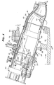
- the gas turbine 10 includes a compressor 12 (partially shown), a plurality of combustors 14 (one shown), and a turbine represented here by a single blade 16. Although not specifically shown, the turbine is drivingly connected to the compressor 12 along a common axis.
- the compressor 12 pressurizes inlet air which is then reverse flowed to the combustor 14 where it is used to cool the combustor and to provide air to the combustion process.
- the gas turbine includes a plurality of combustors 14 located about the periphery of the gas turbine.
- a double-walled transition duct 18 connects the outlet end of each combustor with the inlet end of the turbine to deliver the hot products of combustion to the turbine. Ignition is achieved in the various combustors 14 by means of spark plug 20 in conjunction with cross fire tubes 22 (one shown) in the usual manner.
- Each combustor 14 includes a substantially cylindrical combustion casing 24 which is secured at an open forward end to the turbine casing 26 by means of bolts 28.
- the rearward end of the combustion casing is closed by an end cover assembly 30 which includes conventional supply tubes, manifolds and associated valves, etc., for feeding gas, liquid fuel and air (and water if desired) to the combustor as described in greater detail below.
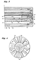
- the end cover assembly 30 receives a plurality (for example, five) of fuel nozzle assemblies 32 (only one shown for purposes of convenience and clarity) arranged in a symmetric circular array about a longitudinal axis of the combustor (see Figure 5).
- a substantially cylindrical flow sleeve 34 which connects at its forward end to the outer wall 36 of the double-walled transition duct 18.
- the flow sleeve 34 is connected at its rearward end by means of a radial flange 35 to the combustor casing 24 at a butt joint 37 where fore and aft sections of the combustor casing 24 are joined.
- combustion liner 38 which is connected at its forward end with the inner wall 40 of the transition duct 18.
- the rearward end of the combustion liner 38 is supported by a combustion liner cap assembly 42 which is, in turn, supported within the combustor casing by a plurality of struts 39 and associated mounting flange assembly 41 (best seen in Figure 5).
- the outer wall 36 of the transition duct 18, as well as that portion of flow sleeve 34 extending forward of the location where the combustion casing 24 is bolted to the turbine casing (by bolts 28), are formed with an array of apertures 44 over their respective peripheral surfaces to permit air to reverse flow from the compressor 12 through the apertures 44 into the annular space between the flow sleeve 34 and the liner 38 toward the upstream or rearward end of the combustor (as indicated by the flow arrows shown in Figure 1).
- the combustion liner cap assembly 42 supports a plurality of premix tubes 46, one for each fuel nozzle assembly 32. More specifically, each premix tube 46 is supported within the combustion liner cap assembly 42 at its forward and rearward ends by front and rear plates 47, 49, respectively, each provided with openings aligned with the open-ended premix tubes 46. This arrangement is best seen in Figure 5, with openings 43 shown in the front plate 47.
- the front plate 47 an impingement plate provided with an array of cooling apertures
- shield plates 45 may be shielded from the thermal radiation of the combustor flame by shield plates 45.
- the rear plate 49 mounts a plurality of rearwardly extending floating collars 48 (one for each premix tube 46, arranged in substantial alignment with the openings in the rear plate), each of which supports an air swirler 50 in surrounding relation to a radially outermost tube of the nozzle assembly 32.
- the arrangement is such that air flowing in the annular space between the liner 38 and flow sleeve 34 is forced to again reverse direction in the rearward end of the combustor (between the end cap assembly 30 and sleeve cap assembly 44) and to flow through the swirlers 50 and premix tubes 46 before entering the burning zone within the liner 38, downstream of the premix tubes 46.
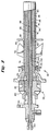
- each fuel nozzle assembly 32 includes a rearward supply section 52 with inlets for receiving liquid fuel, atomizing air, diffusion gas fuel and premix gas fuel, and with suitable connecting passages for supplying each of the above mentioned fluids to a respective passage in a forward delivery section 54 of the fuel nozzle assembly, as described below.
- the forward delivery section 54 of the fuel nozzle assembly is comprised of a series of concentric tubes 56, 58.
- the tubes 56 and 58 provide a premix gas passage 60 which receives premix gas fuel from an inlet 62 connected to passage 60 by means of conduit 64.
- the premix gas passage 60 also communicates with a plurality (for example, eleven) radial fuel injectors (pegs) 66, each of which is provided with a plurality of fuel injection ports or holes 68 for discharging gas fuel into a premix zone 69 located within the premix tube 46.
- the injected fuel mixes with air reverse flowed from the compressor 12, and swirled by means of the annular swirler 50 surrounding the fuel nozzle assembly upstream of the radial injectors 66.
- the premix passage 60 is sealed by an O-ring 72 at the forward or discharge end of the fuel nozzle assembly, so that premix fuel may exit only via the radial fuel injectors 66.
- the next adjacent passage 74 is formed between concentric tubes 58 and 76, and supplies diffusion gas to the burning zone 70 of the combustor via orifice 78 at the forwardmost end of the fuel nozzle assembly 32.
- the forwardmost or discharge end of the nozzle is located within the premix tube 46, but relatively close to the forward end thereof.
- the diffusion gas passage 74 receives diffusion gas from an inlet 80 via conduit 82.
- a third passage 84 is defined between concentric tubes 76 and 86 and supplies atomizing air to the burning zone 70 of the combustor via orifice 88 where it then mixes with diffusion fuel exiting the orifice 78.
- the atomizing air is supplied to passage 84 from an inlet 90 via conduit 92.
- the fuel nozzle assembly 32 is also provided with a further passage 94 for (optionally) supplying water to the burning zone to effect NO x reductions in a manner understood by those skilled in the art.
- the water passage 94 is defined between the tube 86 and adjacent concentric tube 96. Water exits the nozzle via an orifice 98, radially inward of the atomizing air orifice 88.
- Tube 96 the innermost of the series of concentric tubes forming the fuel injector nozzle, itself forms a central passage 100 for liquid fuel which enters the passage by means of inlet 102.
- the liquid fuel exits the nozzle by means of a discharge orifice 104 in the center of the nozzle.
- passage 100 is normally purged with compressor discharge air while the turbine is in its normal gas fuel mode.
- diffusion gas fuel is fed through inlet 80, conduit 82 and passage 74 for discharge via orifice 78 into the burning zone 70, where it mixes with atomizing air, is ignited by sparkplug 20 and burned in the zone 70 within the liner 38 during a diffusion mode of operation.
- premix gas fuel is supplied to the passages 60 via inlet 62 and conduit 64 for discharge through orifices 68 in downstream radial injectors 66.
- the premix fuel mixes with air, entering the premix tube 46 by means of swirlers 50, the mixture igniting in burning zone 70 in liner 38 by the preexisting flame from the diffusion mode of operation.
- premix fuel is supplied to the manifold 106 for flow through the radially projecting pegs 105 upstream of the swirlers 50.
- the fuel flow through radial pegs 105 into the airstream from the compressor flows past the swirlers 50 and is combined with the premix fuel injected into the airstream via pegs 66. Consequently, pegs 66 and 105 stage the fuel flow into the combustor at different axial locations.
- the present invention stages the fuel to the fuel nozzles in a manner which will now be described to minimize or eliminate those tendencies, as well as to enable operation in a premixed mode over a wider load range of the turbine than previously believed possible and without adversely impacting emissions.
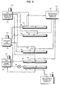
- FIG. 6 there is schematically represented a diffusion fuel manifold 110 for supplying diffusion fuel to the diffusion fuel inlet passages 80 of the various nozzles 32.
- a valve 112 may be located in the manifold 110 to open and close the supply of fuel from manifold 110 to the nozzles.
- a valve 114 may be disposed in the diffusion fuel line to one or more of the diffusion fuel nozzles.
- a first downstream premix manifold 116 for supplying premix fuel to certain of the nozzles and a second downstream premix manifold 118 for supplying fuel to the remaining one or more nozzles.
- the first and second downstream premix manifolds have valves 120 and 122, respectively, movable between open and closed positions to supply fuel or not to the connected nozzles.
- Individual valves can be located in the individual supply lines as desirable and it will be appreciated that the manifold valves, as well as any valves disposed in the fuel supply lines, will be operated in a conventional manner.
- a first upstream premix fuel manifold 130 is provided for supplying premix fuel to each of the four nozzles by way of the manifolds 106 about those nozzles.
- the first upstream premix manifold 130 is under the control of a valve 132 to open and close the supply of fuel from manifold 130 to the nozzles.
- a second upstream premix fuel manifold 134 is provided for supplying premix fuel to the fifth premix nozzle via manifold 106 about that nozzle.
- a valve 136 is located in manifold 134 to open and close the supply of fuel from the manifold 134 to the fifth nozzle.
- the valve 112 is opened to supply diffusion fuel from manifold 110 to each of the nozzles 32 or to a lesser number of the nozzles, for example, by closing valve 114, or by omitting a diffusion fuel supply line entirely to one or more of the nozzles.
- load is applied to the turbine.
- the diffusion fuel is supplied only to four of the five nozzles, as illustrated, and the fifth nozzle is totally disconnected from the diffusion fuel manifold and supplies only air to the fifth nozzle during start-up.
- the combustor As load is applied, for example, within a range of 30 to 50% of full power, the combustor is transitioned from operation in a diffusion mode to operation in a premixed mode in the manner set forth in companion application (51DV-05218) a copy of which is available in the dossier of this application.
- first and second upstream premix manifolds 130, 134, respectively would be combined into a single premix manifold feeding all five nozzles 32 symmetrically and simultaneously.
- the fuel split between the premix nozzles is modulated to provide substantially equal fuel flow to the premix nozzles, although the proportion of the fuel flow through the upstream premix injectors 105 is much less than the proportion of total fuel flow to the downstream injectors 66.
- the ability to vary the fuel split across the combustor enables utilization of premix nozzles designed for low NO x and CO emissions performance and which exhibit desirable stability and combustion dynamics characteristics.
- the supply of fuel to the upstream injectors tracks the supply of fuel to the downstream injectors by using a similar system for each set of axially spaced injectors.
- a common manifold for the four upstream premix nozzles and the one upstream premix nozzle could be utilized whereby the fuel flow would be a fixed percentage of the fuel flow to the downstream manifolds. The percentage is fixed by setting the appropriate effective area of the upstream fuel injection pegs relative to the downstream fuel injection pegs on the common manifold, instead of varying fuel flow by means of valves.
- the upstream fuel may be fixed or a variable percentage of total fuel.
- the upstream fuel may be fed evenly to all five nozzles or may be split unevenly between the one and the four premix nozzles. In either case, the split of total fuel between the one and the four nozzles can still be separately controlled by simultaneously adjusting the split of fuel fed through the downstream pegs.
- the upstream premix fuel can be distributed equally to all five nozzles through a single manifold.
- the single manifold would supply fuel to the manifold 106 surrounding each nozzle and may have an independently controlled fuel supply so that the ratio of upstream fuel to total fuel is variable.
- the downstream fuel flow to the one and the four nozzles can be cut back in equal proportions to maintain a constant fuel split between the one and the four premix nozzles.
Landscapes
- Engineering & Computer Science (AREA)
- Chemical & Material Sciences (AREA)
- Combustion & Propulsion (AREA)
- Mechanical Engineering (AREA)
- General Engineering & Computer Science (AREA)
Claims (10)
- Procédé pour faire fonctionner une chambre de combustion (14) pour turbine (10) à gaz, comportant les étapes consistant à faire entrer un combustible de prémélange (62) dans la chambre de combustion (14) à des emplacements (66, 105) espacés de manière axiale le long de la chambre de combustion (14) pendant un fonctionnement en mode prémélange, caractérisé par une régulation variable du débit de combustible vers une seule zone de combustion aval pour créer un écoulement asymétrique du combustible à travers la chambre de combustion.
- Procédé pour faire fonctionner une chambre de combustion (14) pour turbine (10) à gaz, la chambre de combustion (14) ayant une pluralité de distributeurs (32) de combustible en groupe annulaire autour d'un axe de la chambre de combustion (14) et une coupelle rotative (50) autour de chaque distributeur (32) pour faire pivoter l'air traversant la chambre de combustion (14), comportant les étapes consistant à faire entrer un combustible de prémélange dans une zone de combustion en aval des distributeurs (32) et depuis des côtés axiaux opposés (66, 105) de ladite coupelle rotative (50) pendant un fonctionnement en mode prémélange, et créer un écoulement asymétrique de combustible à travers la chambre de combustion (14) jusqu'à la zone de combustion.
- Procédé selon la revendication 1 ou 2, comportant l'étape supplémentaire consistant à créer l'écoulement asymétrique de combustible pendant un fonctionnement à mode diffusion.
- Procédé selon la revendication 1 ou 2, comportant l'étape supplémentaire consistant à créer l'écoulement asymétrique de combustible pendant la transition entre un fonctionnement à mode diffusion et un fonctionnement à mode prémélange.
- Procédé selon la revendication 1 ou 2, comportant les étapes supplémentaires consistant à créer l'écoulement asymétrique de combustible à la fois pendant un fonctionnement à mode diffusion et pendant la transition entre ledit fonctionnement en mode diffusion et un mode de fonctionnement à prémélange.
- Procédé selon la revendication 1, 2 ou 3, comportant les étapes supplémentaires consistant à créer l'écoulement asymétrique de combustible à la fois pendant (I) la transition entre un fonctionnement en mode diffusion et un fonctionnement en mode prémélange et (II) le fonctionnement en mode prémélange.
- Procédé selon la revendication 1, dans lequel la chambre de combustion (14) a une pluralité de distributeurs (32), le procédé comportant les étapes consistant à :faire passer le combustible par au moins certains distributeurs de ladite pluralité de distributeurs (32) fonctionnant en mode diffusion ;pendant la transition d'un fonctionnement en mode diffusion à un fonctionnement en mode prémélange, faire passer le combustible jusqu'à la zone de combustion via au moins un distributeur de ladite pluralité de distributeurs (32) fonctionnant en mode prémélange tout en continuant à faire fonctionner certains distributeurs (32) en mode diffusion ; et faire entrer le combustible de prémélange dans la chambre de combustion (14) à des emplacements (66, 105) espacés de manière axiale le long de la chambre de combustion (14) pendant le fonctionnement en mode prémélange et commander de manière variable le débit de combustible dans ces distributeurs (32) pour créer un écoulement asymétrique de combustible à travers la chambre de combustion (14) jusqu'à la zone de combustion en aval desdits distributeurs (32).
- Procédé selon la revendication 7, comportant l'étape consistant à disposer des coupelles rotatives (50) en amont de la zone de combustion pour faire tourbillonner l'air traversant la chambre de combustion (14) et injecter un combustible de prémélange dans la chambre de combustion (14) à des emplacements axiaux respectivement en amont et en aval desdites coupelles rotatives (50).
- Procédé selon la revendication 7 ou 8, comportant, après ladite transition, l'étape consistant à faire fonctionner tous les distributeurs (32) en mode prémélange.
- Procédé selon la revendication 7 ou 8, comportant, après ladite transition, les autres étapes consistant à faire fonctionner tous les distributeurs (32) en mode prémélange, à commander de manière variable le débit dans la totalité desdits distributeurs (32) pour créer un écoulement asymétrique de combustible à travers la chambre de combustion (14) pendant le fonctionnement de tous les distributeurs (32) en mode prémélange.
Applications Claiming Priority (2)
| Application Number | Priority Date | Filing Date | Title |
|---|---|---|---|
| US25804194A | 1994-06-10 | 1994-06-10 | |
| US258041 | 1994-06-10 |
Publications (2)
| Publication Number | Publication Date |
|---|---|
| EP0686812A1 EP0686812A1 (fr) | 1995-12-13 |
| EP0686812B1 true EP0686812B1 (fr) | 2000-03-29 |
Family
ID=22978849
Family Applications (1)
| Application Number | Title | Priority Date | Filing Date |
|---|---|---|---|
| EP95303205A Expired - Lifetime EP0686812B1 (fr) | 1994-06-10 | 1995-05-12 | Méthode de régulation pour une chambre de combustion d'une turbine à gaz |
Country Status (5)
| Country | Link |
|---|---|
| US (1) | US5551228A (fr) |
| EP (1) | EP0686812B1 (fr) |
| JP (1) | JP3703879B2 (fr) |
| KR (1) | KR100352805B1 (fr) |
| DE (1) | DE69515931T2 (fr) |
Families Citing this family (49)
| Publication number | Priority date | Publication date | Assignee | Title |
|---|---|---|---|---|
| US5943866A (en) * | 1994-10-03 | 1999-08-31 | General Electric Company | Dynamically uncoupled low NOx combustor having multiple premixers with axial staging |
| US5722230A (en) * | 1995-08-08 | 1998-03-03 | General Electric Co. | Center burner in a multi-burner combustor |
| DE19615910B4 (de) * | 1996-04-22 | 2006-09-14 | Alstom | Brenneranordnung |
| US6269646B1 (en) * | 1998-01-28 | 2001-08-07 | General Electric Company | Combustors with improved dynamics |
| EP0976982B1 (fr) * | 1998-07-27 | 2003-12-03 | ALSTOM (Switzerland) Ltd | Procédé de fonctionnement d'une chambre de combustion de turbine à gaz à carburant liquide |
| US6598383B1 (en) * | 1999-12-08 | 2003-07-29 | General Electric Co. | Fuel system configuration and method for staging fuel for gas turbines utilizing both gaseous and liquid fuels |
| JP3860952B2 (ja) * | 2000-05-19 | 2006-12-20 | 三菱重工業株式会社 | ガスタービン燃焼器 |
| JP2002031343A (ja) | 2000-07-13 | 2002-01-31 | Mitsubishi Heavy Ind Ltd | 燃料噴出部材、バーナ、燃焼器の予混合ノズル、燃焼器、ガスタービン及びジェットエンジン |
| US6405524B1 (en) | 2000-08-16 | 2002-06-18 | General Electric Company | Apparatus for decreasing gas turbine combustor emissions |
| US6839613B2 (en) * | 2001-07-17 | 2005-01-04 | General Electric Company | Remote tuning for gas turbines |
| US6735949B1 (en) * | 2002-06-11 | 2004-05-18 | General Electric Company | Gas turbine engine combustor can with trapped vortex cavity |
| US6772583B2 (en) | 2002-09-11 | 2004-08-10 | Siemens Westinghouse Power Corporation | Can combustor for a gas turbine engine |
| US6848260B2 (en) | 2002-09-23 | 2005-02-01 | Siemens Westinghouse Power Corporation | Premixed pilot burner for a combustion turbine engine |
| US6868676B1 (en) | 2002-12-20 | 2005-03-22 | General Electric Company | Turbine containing system and an injector therefor |
| US6996991B2 (en) * | 2003-08-15 | 2006-02-14 | Siemens Westinghouse Power Corporation | Fuel injection system for a turbine engine |
| US7284378B2 (en) | 2004-06-04 | 2007-10-23 | General Electric Company | Methods and apparatus for low emission gas turbine energy generation |
| US7370466B2 (en) * | 2004-11-09 | 2008-05-13 | Siemens Power Generation, Inc. | Extended flashback annulus in a gas turbine combustor |
| US20070074518A1 (en) * | 2005-09-30 | 2007-04-05 | Solar Turbines Incorporated | Turbine engine having acoustically tuned fuel nozzle |
| US20080083224A1 (en) * | 2006-10-05 | 2008-04-10 | Balachandar Varatharajan | Method and apparatus for reducing gas turbine engine emissions |
| US7950215B2 (en) * | 2007-11-20 | 2011-05-31 | Siemens Energy, Inc. | Sequential combustion firing system for a fuel system of a gas turbine engine |
| US9354618B2 (en) | 2009-05-08 | 2016-05-31 | Gas Turbine Efficiency Sweden Ab | Automated tuning of multiple fuel gas turbine combustion systems |
| US8437941B2 (en) | 2009-05-08 | 2013-05-07 | Gas Turbine Efficiency Sweden Ab | Automated tuning of gas turbine combustion systems |
| US9671797B2 (en) | 2009-05-08 | 2017-06-06 | Gas Turbine Efficiency Sweden Ab | Optimization of gas turbine combustion systems low load performance on simple cycle and heat recovery steam generator applications |
| US9267443B2 (en) | 2009-05-08 | 2016-02-23 | Gas Turbine Efficiency Sweden Ab | Automated tuning of gas turbine combustion systems |
| US8322140B2 (en) * | 2010-01-04 | 2012-12-04 | General Electric Company | Fuel system acoustic feature to mitigate combustion dynamics for multi-nozzle dry low NOx combustion system and method |
| US8650851B2 (en) * | 2010-01-05 | 2014-02-18 | General Electric Company | Systems and methods for controlling fuel flow within a machine |
| EP2362143B1 (fr) * | 2010-02-19 | 2012-08-29 | Siemens Aktiengesellschaft | Agencement de brûleur |
| US9557050B2 (en) | 2010-07-30 | 2017-01-31 | General Electric Company | Fuel nozzle and assembly and gas turbine comprising the same |
| US8991187B2 (en) | 2010-10-11 | 2015-03-31 | General Electric Company | Combustor with a lean pre-nozzle fuel injection system |
| EP2551470A1 (fr) * | 2011-07-26 | 2013-01-30 | Siemens Aktiengesellschaft | Procédé de démarrage d'une turbine à gaz stationnaire |
| US20130040254A1 (en) * | 2011-08-08 | 2013-02-14 | General Electric Company | System and method for monitoring a combustor |
| US8850821B2 (en) | 2011-10-07 | 2014-10-07 | General Electric Company | System for fuel injection in a fuel nozzle |
| US9395084B2 (en) * | 2012-06-06 | 2016-07-19 | General Electric Company | Fuel pre-mixer with planar and swirler vanes |
| US9310072B2 (en) | 2012-07-06 | 2016-04-12 | Hamilton Sundstrand Corporation | Non-symmetric arrangement of fuel nozzles in a combustor |
| US9562687B2 (en) | 2013-02-06 | 2017-02-07 | General Electric Company | Variable volume combustor with an air bypass system |
| US20140216038A1 (en) * | 2013-02-06 | 2014-08-07 | General Electric Company | Variable Volume Combustor with Cantilevered Support Structure |
| US9587562B2 (en) | 2013-02-06 | 2017-03-07 | General Electric Company | Variable volume combustor with aerodynamic support struts |
| US9422867B2 (en) | 2013-02-06 | 2016-08-23 | General Electric Company | Variable volume combustor with center hub fuel staging |
| US9689572B2 (en) | 2013-02-06 | 2017-06-27 | General Electric Company | Variable volume combustor with a conical liner support |
| US9435539B2 (en) * | 2013-02-06 | 2016-09-06 | General Electric Company | Variable volume combustor with pre-nozzle fuel injection system |
| US9441544B2 (en) | 2013-02-06 | 2016-09-13 | General Electric Company | Variable volume combustor with nested fuel manifold system |
| US9546598B2 (en) | 2013-02-06 | 2017-01-17 | General Electric Company | Variable volume combustor |
| US9447975B2 (en) | 2013-02-06 | 2016-09-20 | General Electric Company | Variable volume combustor with aerodynamic fuel flanges for nozzle mounting |
| EP3008391B1 (fr) | 2013-06-11 | 2020-05-06 | United Technologies Corporation | Chambre de combustion à étagement axial pour un moteur à turbine à gaz |
| JP6190670B2 (ja) * | 2013-08-30 | 2017-08-30 | 三菱日立パワーシステムズ株式会社 | ガスタービン燃焼システム |
| JP6223954B2 (ja) * | 2014-12-02 | 2017-11-01 | 三菱日立パワーシステムズ株式会社 | 燃焼器及びガスタービン |
| JP6740375B2 (ja) * | 2016-05-12 | 2020-08-12 | シーメンス アクティエンゲゼルシャフト | 排気を減らすための選択的燃焼器制御の方法 |
| FR3075931B1 (fr) * | 2017-12-21 | 2020-05-22 | Fives Pillard | Bruleur et ensemble de bruleurs compacts |
| US11629641B2 (en) | 2020-09-29 | 2023-04-18 | General Electric Company | Fuel distribution manifold |
Family Cites Families (12)
| Publication number | Priority date | Publication date | Assignee | Title |
|---|---|---|---|---|
| US3158998A (en) * | 1962-09-04 | 1964-12-01 | Gen Motors Corp | Automatic control for afterburner manifold utilizing two fluids |
| US4027473A (en) * | 1976-03-05 | 1977-06-07 | United Technologies Corporation | Fuel distribution valve |
| US4100733A (en) * | 1976-10-04 | 1978-07-18 | United Technologies Corporation | Premix combustor |
| DE2949388A1 (de) * | 1979-12-07 | 1981-06-11 | Kraftwerk Union AG, 4330 Mülheim | Brennkammer fuer gasturbinen und verfahren zum betrieb der brennkammer |
| US4417439A (en) * | 1981-07-29 | 1983-11-29 | United Technologies Corporation | Starting means for a gas turbine engine |
| US4499735A (en) * | 1982-03-23 | 1985-02-19 | The United States Of America As Represented By The Secretary Of The Air Force | Segmented zoned fuel injection system for use with a combustor |
| JPS6057131A (ja) * | 1983-09-08 | 1985-04-02 | Hitachi Ltd | ガスタ−ビン燃焼器の燃料供給方法 |
| JP2644745B2 (ja) * | 1987-03-06 | 1997-08-25 | 株式会社日立製作所 | ガスタービン用燃焼器 |
| US4817389A (en) * | 1987-09-24 | 1989-04-04 | United Technologies Corporation | Fuel injection system |
| JP2544470B2 (ja) * | 1989-02-03 | 1996-10-16 | 株式会社日立製作所 | ガスタ―ビン燃焼器及びその運転方法 |
| EP0540167A1 (fr) * | 1991-09-27 | 1993-05-05 | General Electric Company | Chambre de combustion avec prémélange en cascade à émission réduite en NOx |
| US5259184A (en) * | 1992-03-30 | 1993-11-09 | General Electric Company | Dry low NOx single stage dual mode combustor construction for a gas turbine |
-
1995
- 1995-05-12 DE DE69515931T patent/DE69515931T2/de not_active Expired - Lifetime
- 1995-05-12 EP EP95303205A patent/EP0686812B1/fr not_active Expired - Lifetime
- 1995-06-01 JP JP13459995A patent/JP3703879B2/ja not_active Expired - Lifetime
- 1995-06-09 KR KR1019950015135A patent/KR100352805B1/ko not_active Expired - Lifetime
- 1995-08-22 US US08/524,146 patent/US5551228A/en not_active Expired - Lifetime
Also Published As
| Publication number | Publication date |
|---|---|
| KR960001438A (ko) | 1996-01-25 |
| KR100352805B1 (ko) | 2002-12-16 |
| DE69515931D1 (de) | 2000-05-04 |
| US5551228A (en) | 1996-09-03 |
| JP3703879B2 (ja) | 2005-10-05 |
| EP0686812A1 (fr) | 1995-12-13 |
| DE69515931T2 (de) | 2000-11-02 |
| JPH0854119A (ja) | 1996-02-27 |
Similar Documents
| Publication | Publication Date | Title |
|---|---|---|
| EP0686812B1 (fr) | Méthode de régulation pour une chambre de combustion d'une turbine à gaz | |
| US5491970A (en) | Method for staging fuel in a turbine between diffusion and premixed operations | |
| EP0667492B1 (fr) | Injecteur de carburant | |
| EP0564184B1 (fr) | Brûleur simple effet à deux modes d'opération | |
| US7181916B2 (en) | Method for operating a reduced center burner in multi-burner combustor | |
| US5729968A (en) | Center burner in a multi-burner combustor | |
| US6397602B2 (en) | Fuel system configuration for staging fuel for gas turbines utilizing both gaseous and liquid fuels | |
| US5685139A (en) | Diffusion-premix nozzle for a gas turbine combustor and related method | |
| US6935116B2 (en) | Flamesheet combustor | |
| CA1289756C (fr) | Injecteur bimode generateur de tourbillonnement sur chambre de combustion de turbine a gaz | |
| US20090111063A1 (en) | Lean premixed, radial inflow, multi-annular staged nozzle, can-annular, dual-fuel combustor | |
| US20060191268A1 (en) | Method and apparatus for cooling gas turbine fuel nozzles | |
| US20100263382A1 (en) | Dual orifice pilot fuel injector | |
| US6857271B2 (en) | Secondary fuel nozzle with readily customizable pilot fuel flow rate | |
| JP2012229697A (ja) | ガスタービンエンジン内で燃料を燃焼させるための方法及び装置 |
Legal Events
| Date | Code | Title | Description |
|---|---|---|---|
| PUAI | Public reference made under article 153(3) epc to a published international application that has entered the european phase |
Free format text: ORIGINAL CODE: 0009012 |
|
| AK | Designated contracting states |
Kind code of ref document: A1 Designated state(s): DE FR GB IT |
|
| 17P | Request for examination filed |
Effective date: 19960613 |
|
| 17Q | First examination report despatched |
Effective date: 19980126 |
|
| GRAG | Despatch of communication of intention to grant |
Free format text: ORIGINAL CODE: EPIDOS AGRA |
|
| GRAG | Despatch of communication of intention to grant |
Free format text: ORIGINAL CODE: EPIDOS AGRA |
|
| GRAH | Despatch of communication of intention to grant a patent |
Free format text: ORIGINAL CODE: EPIDOS IGRA |
|
| GRAH | Despatch of communication of intention to grant a patent |
Free format text: ORIGINAL CODE: EPIDOS IGRA |
|
| GRAA | (expected) grant |
Free format text: ORIGINAL CODE: 0009210 |
|
| AK | Designated contracting states |
Kind code of ref document: B1 Designated state(s): DE FR GB IT |
|
| ITF | It: translation for a ep patent filed | ||
| ET | Fr: translation filed | ||
| REF | Corresponds to: |
Ref document number: 69515931 Country of ref document: DE Date of ref document: 20000504 |
|
| PLBE | No opposition filed within time limit |
Free format text: ORIGINAL CODE: 0009261 |
|
| STAA | Information on the status of an ep patent application or granted ep patent |
Free format text: STATUS: NO OPPOSITION FILED WITHIN TIME LIMIT |
|
| 26N | No opposition filed | ||
| REG | Reference to a national code |
Ref country code: GB Ref legal event code: IF02 |
|
| PGFP | Annual fee paid to national office [announced via postgrant information from national office to epo] |
Ref country code: GB Payment date: 20140527 Year of fee payment: 20 |
|
| PGFP | Annual fee paid to national office [announced via postgrant information from national office to epo] |
Ref country code: FR Payment date: 20140519 Year of fee payment: 20 Ref country code: DE Payment date: 20140529 Year of fee payment: 20 Ref country code: IT Payment date: 20140526 Year of fee payment: 20 |
|
| REG | Reference to a national code |
Ref country code: DE Ref legal event code: R071 Ref document number: 69515931 Country of ref document: DE |
|
| REG | Reference to a national code |
Ref country code: DE Ref legal event code: R071 Ref document number: 69515931 Country of ref document: DE |
|
| REG | Reference to a national code |
Ref country code: GB Ref legal event code: PE20 Expiry date: 20150511 |
|
| PG25 | Lapsed in a contracting state [announced via postgrant information from national office to epo] |
Ref country code: GB Free format text: LAPSE BECAUSE OF EXPIRATION OF PROTECTION Effective date: 20150511 |