EP0564355A1 - Fotoempfänger für frequenzmodulierte optische Signale - Google Patents
Fotoempfänger für frequenzmodulierte optische Signale Download PDFInfo
- Publication number
- EP0564355A1 EP0564355A1 EP93400831A EP93400831A EP0564355A1 EP 0564355 A1 EP0564355 A1 EP 0564355A1 EP 93400831 A EP93400831 A EP 93400831A EP 93400831 A EP93400831 A EP 93400831A EP 0564355 A1 EP0564355 A1 EP 0564355A1
- Authority
- EP
- European Patent Office
- Prior art keywords
- laser
- frequency
- photoreceptor
- fabry
- optical signals
- Prior art date
- Legal status (The legal status is an assumption and is not a legal conclusion. Google has not performed a legal analysis and makes no representation as to the accuracy of the status listed.)
- Withdrawn
Links
- 230000003287 optical effect Effects 0.000 title claims abstract description 22
- 239000004065 semiconductor Substances 0.000 claims abstract description 11
- 108091008695 photoreceptors Proteins 0.000 claims description 17
- 239000006117 anti-reflective coating Substances 0.000 claims description 4
- 239000011248 coating agent Substances 0.000 claims description 4
- 238000000576 coating method Methods 0.000 claims description 4
- 238000010079 rubber tapping Methods 0.000 abstract 1
- 230000005540 biological transmission Effects 0.000 description 5
- 238000001228 spectrum Methods 0.000 description 5
- 230000008878 coupling Effects 0.000 description 2
- 238000010168 coupling process Methods 0.000 description 2
- 238000005859 coupling reaction Methods 0.000 description 2
- 238000001514 detection method Methods 0.000 description 2
- 230000010287 polarization Effects 0.000 description 2
- 230000003667 anti-reflective effect Effects 0.000 description 1
- 239000003990 capacitor Substances 0.000 description 1
- 238000006243 chemical reaction Methods 0.000 description 1
- 230000001427 coherent effect Effects 0.000 description 1
- 239000000835 fiber Substances 0.000 description 1
- 238000009413 insulation Methods 0.000 description 1
- 238000000034 method Methods 0.000 description 1
- 230000004048 modification Effects 0.000 description 1
- 238000012986 modification Methods 0.000 description 1
- 239000013307 optical fiber Substances 0.000 description 1
- 230000000737 periodic effect Effects 0.000 description 1
- 230000035945 sensitivity Effects 0.000 description 1
Images

Classifications
-
- H—ELECTRICITY
- H04—ELECTRIC COMMUNICATION TECHNIQUE
- H04B—TRANSMISSION
- H04B10/00—Transmission systems employing electromagnetic waves other than radio-waves, e.g. infrared, visible or ultraviolet light, or employing corpuscular radiation, e.g. quantum communication
- H04B10/60—Receivers
- H04B10/66—Non-coherent receivers, e.g. using direct detection
- H04B10/67—Optical arrangements in the receiver
-
- H—ELECTRICITY
- H01—ELECTRIC ELEMENTS
- H01S—DEVICES USING THE PROCESS OF LIGHT AMPLIFICATION BY STIMULATED EMISSION OF RADIATION [LASER] TO AMPLIFY OR GENERATE LIGHT; DEVICES USING STIMULATED EMISSION OF ELECTROMAGNETIC RADIATION IN WAVE RANGES OTHER THAN OPTICAL
- H01S5/00—Semiconductor lasers
- H01S5/0014—Measuring characteristics or properties thereof
- H01S5/0028—Laser diodes used as detectors
Definitions
- the present invention relates to a photoreceptor for frequency modulated optical signals. It finds an application in optical telecommunications.
- modulation for "Frequency Shift Keying" occupies a privileged place. It consists in shifting the frequency of the optical signal transmitted as a function of the information to be transmitted. This modulation is easily obtained with a single frequency semiconductor laser by modulating the bias current.
- the detection of optical signals modulated in FSK is generally carried out either by coherent detection or by direct conversion into intensity modulation using a FABRY-PEROT standard for example.
- the first method requires a local oscillator (usually consisting of a wavelength tunable single frequency laser), a fast photodetector, a signal mixer and complex electronic circuits. It is therefore difficult to implement.
- the second is hardly less so, requiring a servo circuit to tune one of the resonance frequencies of the standard to that of the signal to be demodulated.
- Patent application FR-A-2 652 465 describes another type of photoreceptor for frequency-modulated optical signals which also comprises a semiconductor laser, but which is this time supplied above the laser threshold.
- the variation in electrical voltage across the terminals of the laser is also taken.
- the laser since the supply current is set to a value much higher than the threshold, the laser operates as an oscillator and has its own frequency.
- the sampled voltage then presents, with respect to the natural voltage sampled in the absence of injected beam, a variation the amplitude of which is proportional to the difference between the frequency of the injected beam and the natural frequency of the laser and whose sign is that of said frequency deviation.
- the frequency modulation of the injected light beam is thus directly translated into amplitude modulation of the voltage taken from the terminals of the laser.
- the object of the present invention is precisely to remedy this drawback. To this end, it recommends, still for the reception of frequency modulated signals, to still use a semiconductor laser from which the voltage variation at the terminals is taken, but this laser being devoid of an etched network and using a FABRY- resonator PEROT.
- a FABRY-PEROT standard to demodulate a frequency modulated beam is known per se but, in the past, the standard used was passive.
- the FABRY-PEROT resonator constitutes the resonator of a semiconductor laser. It is therefore part of an active device.
- FABRY-PEROT type semiconductor lasers are also known, but as a fixed frequency generator and not as photoreceptors of frequency modulated optical beam.
- the invention provides a modification of the conventional FABRY-PEROT laser, which consists in covering one of the faces with an anti-reflective coating. This treatment reduces the fineness of the peaks of the FABRY-PEROT laser and allows operation on the quasi-linear parts of the sides of these peaks. This treatment naturally increases the optical losses of the resonator, which must be compensated electrically by supplying the semiconductor structure well above the threshold. For example, the laser is supplied with current approximately three times above the threshold.
- the present invention therefore relates to a photoreceptor for frequency modulated optical signals, this photoreceptor comprising a semiconductor laser with its active layer, a bias current source supplying the laser above the threshold, optical means for injecting a frequency modulated light beam into the active layer of the laser, means for taking the voltage variation electric across the laser, this photo-receiver being characterized in that the laser comprises a FABRY-PEROT type resonator with a first face covered with an anti-reflective coating and receiving the frequency modulated light beam.
- the second side can be either untreated or covered with a reflective coating.
- This coating may include one or more layers.
- threshold current is meant here the threshold current measured before the anti-reflective treatment.
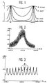
- FIG 3 is shown the spectrum of a laser used as photoreceptor according to the invention.
- the entry face of the FABRY-PEROT laser has been covered by an anti-reflection layer which has caused the reflection coefficient of this face to drop to around 10 ⁇ 5 for example (instead of 33% for a face without treatment).
- the frequency range is from 1522.4 nm to 1532.4 nm. Any of the areas marked Z, located on the side of these peaks, can be used for frequency demodulation.
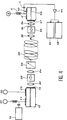
- FIG. 4 shows a bench for testing the photoreceptor of the invention.
- this bench comprises first of all a single frequency optical source tunable in wavelength and frequency modulated.
- This source can be a DFB laser (for example of "Buried Ridge Stripe” structure) whose supply electrode has been separated into two electrodes E1 and E2 connected to two current sources S1 and S2.
- a signal generator 12 makes it possible to modulate the frequency of this laser.
- the length of the cavity can be 425 ⁇ m, with a face 14 treated with anti-reflection at 2%.
- the bench also includes optical means such as a microscope objective 20, for collimating the beams emitted by the laser 10, an isolator 22 (insulation of 38 dB at 1.52 ⁇ m), in order to eliminate the reflections which would disturb the operation of the laser 10, a second objective 24 for coupling the light in the core of a single-mode fiber and a variable optical attenuator 26.
- optical means such as a microscope objective 20, for collimating the beams emitted by the laser 10, an isolator 22 (insulation of 38 dB at 1.52 ⁇ m), in order to eliminate the reflections which would disturb the operation of the laser 10, a second objective 24 for coupling the light in the core of a single-mode fiber and a variable optical attenuator 26.
- first microscope objective 30 On the reception side, there are also various optical means such as a first microscope objective 30, an isolator 32, a second microscope objective 34 making it possible to inject the optical beam 36 into the active layer of the photoreceptor.
- second microscope objective 34 making it possible to inject the optical beam 36 into the active layer of the photoreceptor.
- the photoreceptor referenced 40, comprises a front face 41 treated with an antireflective coating and a reflective rear face, an active layer 43, an electrode E connected to a polarization source S, means for taking the voltage variation across the terminals of the 'electrode E.
- These means may consist of a polarization tee with a coupling capacitor C connected to an amplifier 44 (for example 55 dB).
- the amplifier can supply a spectrum analyzer 46 and an error counter 48.
- the current modulation applied to the DFB laser electrode was 4 mA peak-peak, resulting in a frequency excursion of 2 GHz.
- This frequency response curve has a relatively flat part up to 2 GHz.
- the limitation of the transmission rate was imposed by the frequency response of the transmitting DFB laser.
Landscapes
- Physics & Mathematics (AREA)
- Electromagnetism (AREA)
- Computer Networks & Wireless Communication (AREA)
- General Physics & Mathematics (AREA)
- Optics & Photonics (AREA)
- Engineering & Computer Science (AREA)
- Condensed Matter Physics & Semiconductors (AREA)
- Signal Processing (AREA)
- Semiconductor Lasers (AREA)
- Light Receiving Elements (AREA)
- Digital Transmission Methods That Use Modulated Carrier Waves (AREA)
- Optical Communication System (AREA)
- Spectrometry And Color Measurement (AREA)
Applications Claiming Priority (2)
| Application Number | Priority Date | Filing Date | Title |
|---|---|---|---|
| FR9204005 | 1992-04-02 | ||
| FR9204005A FR2689708B1 (fr) | 1992-04-02 | 1992-04-02 | Photorecepteur pour signaux optiques modules en frequence. |
Publications (1)
| Publication Number | Publication Date |
|---|---|
| EP0564355A1 true EP0564355A1 (de) | 1993-10-06 |
Family
ID=9428389
Family Applications (1)
| Application Number | Title | Priority Date | Filing Date |
|---|---|---|---|
| EP93400831A Withdrawn EP0564355A1 (de) | 1992-04-02 | 1993-03-31 | Fotoempfänger für frequenzmodulierte optische Signale |
Country Status (4)
| Country | Link |
|---|---|
| US (1) | US5404242A (de) |
| EP (1) | EP0564355A1 (de) |
| JP (1) | JPH0677900A (de) |
| FR (1) | FR2689708B1 (de) |
Cited By (2)
| Publication number | Priority date | Publication date | Assignee | Title |
|---|---|---|---|---|
| CN102723985A (zh) * | 2012-06-27 | 2012-10-10 | 长春理工大学 | 光谱幅度编/解码系统的光频码片带宽优化设计方法 |
| CN102829870A (zh) * | 2012-09-05 | 2012-12-19 | 天津奇谱光电技术有限公司 | 一种光学频谱分析设备 |
Families Citing this family (2)
| Publication number | Priority date | Publication date | Assignee | Title |
|---|---|---|---|---|
| EP0733288B1 (de) * | 1994-05-24 | 2004-08-11 | Koninklijke Philips Electronics N.V. | Optoelektronische halbleitervorrichtung mit laser und photodiode |
| DE112004002240T5 (de) * | 2003-11-21 | 2006-11-02 | Sekisui Chemical Co., Ltd. | Positiv arbeitender Photolack und Verfahren zur Erzeugung einer Struktur |
Citations (2)
| Publication number | Priority date | Publication date | Assignee | Title |
|---|---|---|---|---|
| GB2229880A (en) * | 1989-02-08 | 1990-10-03 | American Telephone & Telegraph | Tunable narrowband receiver utilizing distributed Bragg reflector laser structure |
| FR2652465A1 (fr) * | 1989-09-27 | 1991-03-29 | France Etat | Photorecepteur pour signaux optiques modules en frequence. |
Family Cites Families (4)
| Publication number | Priority date | Publication date | Assignee | Title |
|---|---|---|---|---|
| US4730327A (en) * | 1985-12-16 | 1988-03-08 | Lytel Incorporated | Dual channel fabry-perot laser |
| US4861136A (en) * | 1987-07-15 | 1989-08-29 | American Telephone And Telegraph Company | Optical communication systems using fabry-perot cavities |
| US5027435A (en) * | 1987-07-15 | 1991-06-25 | At&T Bell Laboratories | Optical communication systems using Fabry-Perot cavities |
| FR2685590B1 (fr) * | 1991-12-20 | 1995-01-13 | France Telecom | Photorecepteur non selectif pour signaux optiques modules en frequence et liaison optique utilisant ce photorecepteur. |
-
1992
- 1992-04-02 FR FR9204005A patent/FR2689708B1/fr not_active Expired - Fee Related
-
1993
- 1993-03-26 US US08/037,593 patent/US5404242A/en not_active Expired - Fee Related
- 1993-03-31 EP EP93400831A patent/EP0564355A1/de not_active Withdrawn
- 1993-04-02 JP JP5098318A patent/JPH0677900A/ja not_active Withdrawn
Patent Citations (2)
| Publication number | Priority date | Publication date | Assignee | Title |
|---|---|---|---|---|
| GB2229880A (en) * | 1989-02-08 | 1990-10-03 | American Telephone & Telegraph | Tunable narrowband receiver utilizing distributed Bragg reflector laser structure |
| FR2652465A1 (fr) * | 1989-09-27 | 1991-03-29 | France Etat | Photorecepteur pour signaux optiques modules en frequence. |
Non-Patent Citations (1)
| Title |
|---|
| ELECTRONICS LETTERS. vol. 27, no. 23, 7 Novembre 1991, STEVENAGE GB pages 2183 - 2185 P.POTTIER ET AL '1.5 Gbit/s Transmission System using all Optical Wavelength Convertor based on Tunable two-electrode DFB Laser' * |
Cited By (3)
| Publication number | Priority date | Publication date | Assignee | Title |
|---|---|---|---|---|
| CN102723985A (zh) * | 2012-06-27 | 2012-10-10 | 长春理工大学 | 光谱幅度编/解码系统的光频码片带宽优化设计方法 |
| CN102723985B (zh) * | 2012-06-27 | 2014-12-10 | 长春理工大学 | 光谱幅度编/解码系统的光频码片带宽优化设计方法 |
| CN102829870A (zh) * | 2012-09-05 | 2012-12-19 | 天津奇谱光电技术有限公司 | 一种光学频谱分析设备 |
Also Published As
| Publication number | Publication date |
|---|---|
| US5404242A (en) | 1995-04-04 |
| JPH0677900A (ja) | 1994-03-18 |
| FR2689708A1 (fr) | 1993-10-08 |
| FR2689708B1 (fr) | 1994-05-13 |
Similar Documents
| Publication | Publication Date | Title |
|---|---|---|
| FR2512298A1 (fr) | Systeme et methode de modulation de frequence optique | |
| US6088147A (en) | Method and apparatus for transmitting signals in an optical fiber | |
| EP0616398A1 (de) | Verfahren und Vorrichtung zur Erzeugung von optischen Pulsen | |
| FR2772150A1 (fr) | Modulateur optique utilisant un isolateur et transmetteur optique comprenant le susdit | |
| EP0222810B1 (de) | Optische homodyne detektion | |
| EP0231015B1 (de) | Kohärente photonische Fernmeldeeinrichtung | |
| CA2238923C (fr) | Systeme de transmission optique a compensation dynamique de la puissance transmise | |
| Dong et al. | Directly reflectivity modulated laser | |
| EP0420742B1 (de) | Fotoempfänger für frequenzmodulierte optische Signale | |
| EP0071309B1 (de) | Einrichtung zur Kopplung eines Senders und eines Strahlungsempfängers an ein Ende eines Lichtwellenleiters | |
| EP0564355A1 (de) | Fotoempfänger für frequenzmodulierte optische Signale | |
| EP0373945A1 (de) | Phasenmodulation | |
| EP0643459A1 (de) | Verfahren zur gleichzeitigen Umwandlung optischer Modulation in eine Vielzahl von Wellenlängen | |
| EP0926502A2 (de) | Optoelektronisches Antennentestsystem | |
| EP0550309B1 (de) | Nichtselektiver Fotoempfänger für frequenzmodulierte optische Signale und optische Verbindung unter Verwendung dieses Fotoempfänger | |
| Delavaux et al. | Dependence of optical receiver sensitivity, in a 147-Mbit/s heterodyne DPSK system, as a function of optical and electrical parameter variations | |
| EP0618654B1 (de) | Lichtintensitätsmodulator unter Verwendung eines DFB Lasers mit zwei Elektroden | |
| Hilt | Transmission et traitement optiques des signaux dans les systèmes de télécommunications hertziens | |
| EP0598387B1 (de) | Optische Übertragungsstrecke und Verzerrungsverminderungstechnik | |
| Cartledge et al. | Influence of modulator chirp in assessing the performance implications of the group delay ripple of dispersion compensating fiber Bragg gratings | |
| EP0643460B1 (de) | Verfahren zur abstimmbaren Wellenlängenänderung von moduliertem Licht | |
| Namihira et al. | Polarisation fluctuation in optical-fibre submarine cable under 8000 m deep sea environmental conditions | |
| Pan | Microwave and millimeter-wave electro-optic modulators | |
| Nakajima et al. | Generation of 10-Gbit/s optical millimeter-wave signal using a 125-GHz mode-locked laser diode integrated with an electro-absorption modulator | |
| JP2900529B2 (ja) | 半導体レーザの高周波応答特性測定装置 |
Legal Events
| Date | Code | Title | Description |
|---|---|---|---|
| PUAI | Public reference made under article 153(3) epc to a published international application that has entered the european phase |
Free format text: ORIGINAL CODE: 0009012 |
|
| AK | Designated contracting states |
Kind code of ref document: A1 Designated state(s): DE GB |
|
| 17P | Request for examination filed |
Effective date: 19940310 |
|
| GRAG | Despatch of communication of intention to grant |
Free format text: ORIGINAL CODE: EPIDOS AGRA |
|
| 17Q | First examination report despatched |
Effective date: 19970604 |
|
| GRAG | Despatch of communication of intention to grant |
Free format text: ORIGINAL CODE: EPIDOS AGRA |
|
| GRAH | Despatch of communication of intention to grant a patent |
Free format text: ORIGINAL CODE: EPIDOS IGRA |
|
| STAA | Information on the status of an ep patent application or granted ep patent |
Free format text: STATUS: THE APPLICATION IS DEEMED TO BE WITHDRAWN |
|
| 18D | Application deemed to be withdrawn |
Effective date: 19971230 |